Abstract
In actual engineering, asymmetric flow often occurs, but rigid partitions are often installed in the direction of the flow field and are symmetric in the flow direction. This will result in a deflection angle between the dividing plate and the direction of the incoming flow. The research results show that when the declination angle is low, the partition plate has a limited impact on the system; when the deflection angle is about 10 degrees, the system vibration characteristics will have abrupt changes, the amplitude will decrease, and the vortex frequency will increase; at the deflection angle 10 degrees to 45 degrees As the declination angle increases, the amplitude increases, and the vortex frequency decreases; it can be seen from the motion trajectory that the declination angle changes suddenly after 10 degrees, and the system has a small amplitude between 10 degrees and 25 degrees. That is, in this declination interval, the partition plate has a better control effect on the vibration of the cylindrical system.
1. Introduction
Installing a divider at the tail of the bluff body will increase the pressure at the tail of the system and reduce the resistance of the system. Even when the divider is short, the resistance will change greatly [1]. Studies have found that when the length of the separator is 5 times the diameter of the cylinder, the formation of vortices can be effectively suppressed; when the length of the separator is similar to that of the cylinder, the overall Strouhal number of the system will be significantly reduced [2]. There are few studies on vortex-induced vibration of elastically constrained two-degree-of-freedom systems. Overset mesh can handle the real-time adjustment of dynamic grids in unsteady problems. In this paper, the Shear-Stress Transport (SST) k-omega turbulence model is used to solve the RANS equation, combined with the technology of overlapping grids for data transfer, so that the flow field with large deformation can be calculated and analyzed, and the boundary layer More reliable simulation.
When the length of the splitter plate is equal to the characteristic size of the cylinder, the vortex can be formed just at the end of the splitter plate. At this time, the minimum resistance appears, which is only 69 % of the flow around a normal cylinder [3]. Narendran et al. numerically simulated a cylinder with low mass ratio at high Reynolds number, obtained the phase relationship between displacement and lift coefficient, and studied the relationship between cylinder vibration response and reduced velocity [4]. In actual engineering, asymmetric flow often occurs, which will cause a deflection angle between the splitter plate and the direction of the incoming flow. The splitter plate at different deflection angles will change the formation of the wake field vortex of the cylinder, thereby changing the pressure distribution in the flow field, and the drag coefficient and lift coefficient will also change accordingly. Therefore, in order to determine the characteristics of the flow field when the splitter plate deviates from the flow direction, this paper numerically simulates the movement of the splitter plate at different angles, and studies the system drag coefficient and vortex frequency at different deflection angles. This paper uses the overset mesh to achieve this result [5].
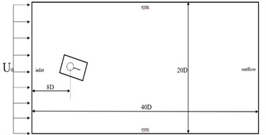
2. Physical model and calculation area
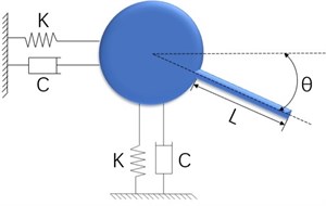
Fig. 1 shows the model when there is a deflection angle between the dividing plate and the incoming flow angle. The diameter of the cylinder is , the length of the dividing plate is , and . The angle taken in this paper is from 0 to 45 degrees, and the calculation and analysis are performed every 5 degrees. The angle increases in a clockwise direction to analyze the vibration of the system with two degrees of freedom. Fig. 1 shows the calculation area of the flow field. The calculation area of the flow field is in the range of 20D×40D, and the origin is located at the center of the cylinder. The distance from the origin to the upstream inlet is 8D, the distance from the downstream outlet is 32D, and the distance from both sides is 10D. The flow direction flows from left to right, the left side is set as the speed inlet, and the right side is the flow outlet. The uniform velocity U is adopted and the relative pressure is 0. The upper and lower boundaries are taken as free-slip wall symmetry, and the surface of the bluff body model is a non-slip wall, that is, the surface fluid velocity is equal to the cylinder movement velocity. De Araujo et al. used direct numerical simulation DNS to study different plate lengths under different Reynolds numbers. It was found that in the laminar flow state, the separation plate length had a great influence on the flow characteristics, but in the subcritical state, the influence of plate length was relatively small. These studies hope to obtain the relationship between the partition plate length and Reynolds number and Strouhal number by means of experiment and numerical simulation, and predict how to select the best geometric parameters in practice [6].
Fig. 1Physical model and calculation area
3. Results
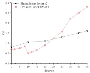
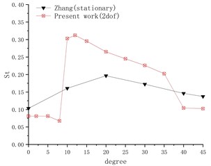
Fig. 2 shows the calculation results of the vibration response of the cylinder-partition plate system under different inflow angles, and compares it with the literature [7]. The system constraint conditions in the literature are fixed, and the numerical simulation results are in a flow field with a low Reynolds number 500. It can be seen from Fig. 2(a) that the resistance coefficient of the cylinder gradually increases as the deflection angle of the partition plate increases, but a sudden change occurs near the deflection angle of 10 degrees. This is because when the deflection angle is small, the separating plate will extend the length of the vortex area of the tail, which delays the interaction of the shear layer. Dai et al. did numerical simulation on different lengths of partition plates to study their effect on three-dimensional fixed cylindrical partition plate system at high Reynolds number. The research shows that the ratio of the length of the divider plate to the diameter of the cylinder is the key parameter for the divider plate control technology to suppress the vortex shedding and thus the unstable flow field force on the cylinder [8].
When the deflection angle increases, the characteristic size of the flow direction of the separator is affected, and the projection of the separator in the flow direction becomes shorter, the vortex formation area becomes shorter, and the is reduced. With the further increase of the deflection angle, the lateral feature size of the partition plate becomes larger, which hinders the flow, reduces the flow velocity, and the lateral force component of the cylinder also increases [6]. After the deflection angle is greater than 10 degrees, the resistance it receives gradually increases. The drag coefficient of the system under two degrees of freedom increases faster than the force on the fixed system. It can be seen from the figure that as the deflection angle increases, the vortex shedding frequency first increases and then decreases, similar to the trend in the literature. The vortex frequency has a big sudden change after 10 degrees, and then with the further increase of the deflection angle, the vortex frequency gradually decreases. After the deflection angle reaches 40 degrees, there is a small sudden change in the frequency, and the frequency at this time is still greater than the frequency when the angle is 10.
Fig. 2Calculation results under different deflection angles
a) Cd
b) St
Fig. 3 shows the displacement trajectory of a cylindrical system with splitter plate at different deflection angles. When the angle is 5, the trajectory is peculiar, which can be confirmed by the multiple peaks of the two-way frequency. There is a sudden change in the displacement trajectory graph between 5 degrees and 10 degrees, and the displacement trajectory has shrunk a lot. This also leads to a sudden change in frequency when the flow velocity approaches. Since the distance of the movement in the same time becomes shorter, more vortices will fall off, which can be observed more clearly from the flow field analysis later. Between 10 degrees and 35 degrees, the trajectory gradually moved from below the origin to above the origin. This is because the flow velocity of the incoming stream surface is reduced, which leads to an increase in the incoming stream surface pressure.
Fig. 3Displacement trajectory at different deflection angles
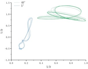
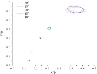
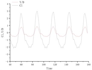
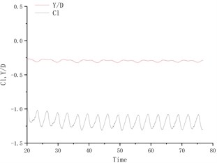
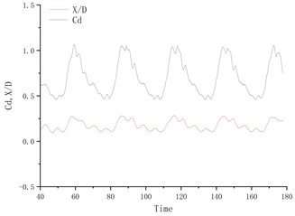
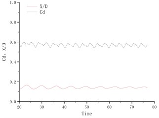
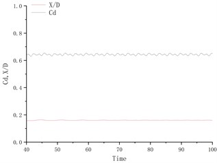
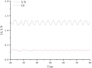
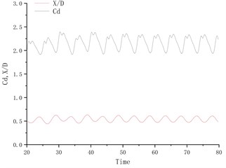
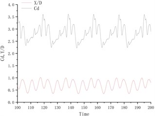
Fig. 4 shows the time history curve of lift coefficient and lateral amplitude at different deflection angles. Fig. 5 shows the time history curve of drag coefficient and flow amplitude at different deflection angles. As the deflection angle changes to 10 degrees, it is found that the lift coefficient and the transverse amplitude time history curve change greatly, no longer vibrating up and down on the center line of the flow, but a small amplitude on one side, and the frequency is 5 compared to the deflection angle. The degree increases a lot. Between 15 degrees and 25 degrees of deflection, the system is in a state of small amplitude and high frequency vibration. In the process of increasing lift, the center of vibration also moves from one side of the center line to the other side of the center line. In this process, since the vibration frequency of the flow direction is very close to that of the lateral direction, the vibration amplitude of the system is very small, and the motion trajectory presents a circular shape at a certain deflection angle. The vibration characteristics of the single-cylinder system under different deflection angles are not much different. It can be seen that the deflection angle of the partition plate is about 10 degrees, which makes the vibration system have a small amplitude and has a good control effect on the vibration amplitude. It should also be noted that the frequency at this time increases sharply, approaching the natural frequency of the system. After the deflection angle is increased to 30 degrees, the drag coefficient and the lift coefficient are no longer regular sine functions, and the trajectory of the motion becomes more complicated from a circular trajectory.
Fig. 4Y/D at different deflection angles
a) Degree = 5°
b) Degree = 10°
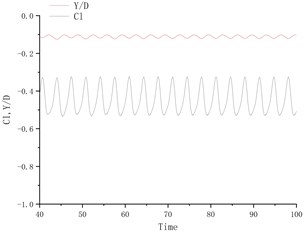
c) Degree = 15°
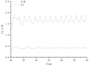
d) Degree = 25°
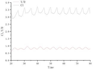
e) Degree = 30°
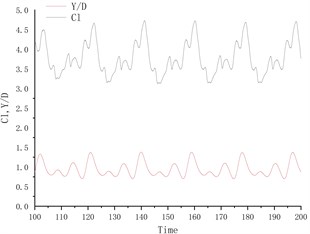
f) Degree = 40°
Fig. 6 shows the vorticity diagrams of the wake field of the cylindrical separator system at different deflection angles. At different deflection angles, the divider will cause the system to produce different wake modes. In the flow field diagram shown in the figure, red represents a positive vortex, that is, a counterclockwise vortex, and blue represents a negative vortex, that is, a clockwise vortex. When the deflection angle is 5 degrees, the wake mode is the 2S mode. After the deflection angle reaches 10 degrees, the displacement trajectory of the system is very small at this time, and the flow field obtained behind the system is particularly stable, similar to the flow field around a fixed cylinder. When the declination angle is smaller, after the declination angle is greater than 10 degrees, the wake field has been in the 2S mode, the vortex volume continues to increase, and the vortex detachment frequency continues to decrease. It can also be found from the vortex diagram that the vortex range becomes larger and the number decreases.
Fig. 5X/D at different deflection angles
a) Degree = 5°
b) Degree = 10°
c) Degree = 15°
d) Degree = 25°
e) Degree = 30°
f) Degree = 40°
Fig. 6Wake vorticity diagram at different declination angles
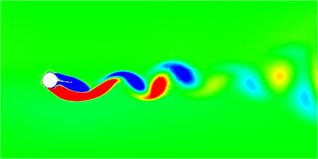
a) Degree = 5°
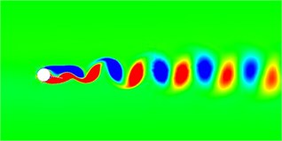
b) Degree = 10°
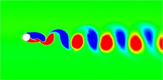
c) Degree = 15°
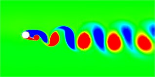
d) Degree = 25°
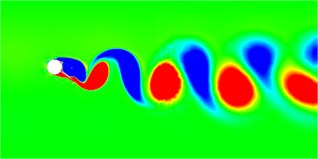
e) Degree = 30°
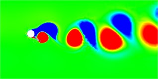
f) Degree = 40°
4. Conclusions
The deflection angle changes suddenly after 10 degrees. Between 10 degrees and 25 degrees, the system has a very small amplitude. In this deflection angle interval, the partition plate has a better control effect on the vibration of the cylindrical system. When the deflection angle is about 10 degrees, the vibration characteristics of the system will have a sudden change, the amplitude will decrease, and the vortex frequency will increase. Between the deflection angle of 10 degrees and 45 degrees, as the deflection angle increases, the amplitude increases, and the vortex frequency decreases.
References
-
J. Zhao, S. C. Pan, and L. Lv, “Large eddy simulation of flow past a circle cylinder with splitter plate based on three-step finite element method,” China Offshore Oil and Gas, Vol. 21, No. 5, pp. 347–351, 2009.
-
L. Zhang and L. Ding, “Research progress of the control technology of the splitter plate for the flow around the blunt body,” Advances in Mechanics, Vol. 41, No. 4, pp. 391–399, 2011.
-
C. J. Apelt and G. S. Westand A. A. Szewczy, “The effects of wake splitter plates on the flow past a circular cylinder in the range 104< Re < 5 × 10⁴,” Journal of Fluid Mechanics Digital Archive, Vol. 61, No. 1, pp. 187–198, 1973.
-
K. Narendran, K. Murali, and V. Sundar, “Vortex-induced vibrations of elastically mounted circular cylinder at Re of the O(105),” Journal of Fluids and Structures, Vol. 54, pp. 503–521, Apr. 2015, https://doi.org/10.1016/j.jfluidstructs.2014.12.006
-
W. W. Zhao, “Research on numerical methods and applications of vortex-induced motions of column-stabilized floating platforms,” Shanghai Jiaotong University, 2019.
-
L. A. Araujo, E. B. C. Schettini, and J. H. Silvestrini, “Direct numerical simulation of the flow around a cylinder with splitter plate: analysis for moderated Reynolds numbers,” Journal of the Brazilian Society of Mechanical Sciences and Engineering, Vol. 40, No. 6, pp. 1–13, Jun. 2018, https://doi.org/10.1007/s40430-018-1199-0
-
L. Zhang and L. Ding, “Effect of drift angle of splitter plate on flow over a circular cylinder,” Journal of Engineering Thermophysics, No. 10, pp. 1695–1698, 2011.
-
S. Dai, B. A. Younis, H. Zhang, and C. Guo, “Prediction of vortex shedding suppression from circular cylinders at high Reynolds number using base splitter plates,” Journal of Wind Engineering and Industrial Aerodynamics, Vol. 182, pp. 115–127, Nov. 2018, https://doi.org/10.1016/j.jweia.2018.09.006
-
G. R. S. Assi, P. W. Bearman, and N. Kitney, “Low drag solutions for suppressing vortex-induced vibration of circular cylinders,” Journal of Fluids and Structures, Vol. 25, No. 4, pp. 666–675, May 2009, https://doi.org/10.1016/j.jfluidstructs.2008.11.002
About this article

