Abstract
To enhance the moving stability and safety of vehicles, kinematics and dynamics model of the vehicle consisting of a guided front wheel and a free rear wheel is established based on the model of a four-wheeled vehicle when the vehicle moves on the curve-road. The effect of the geometrical parameters and dynamics parameters including the factor of the moving stability, vehicle moving speed, lateral stiffness parameters of the front and rear wheels, vehicle mass, vehicle length on the vehicle moving stability and safety is then simulated and analyzed, respectively. The research results indicate that the operating parameters of the vehicle greatly affect the vehicle moving stability. The lateral stiffness parameters of the front and rear wheels should be increased while the vehicle mass needs to be reduced in the operating condition of the vehicle to enhance the vehicle moving stability. Besides, the vehicle length should be reduced and the longitudinal distance of a needs to be distributed by 0.95× to further improve the vehicle moving stability.
1. Introduction
In recent years, the car's market has required increasingly not only on the vehicle's performance and ride comfort but also the stability and safety in the moving process of the vehicle with its high speeds. To enhance the ride comfort of vehicles, the design and optimization of the vehicle dynamic parameters were performed [1-3]. Additionally, the vehicle’s suspension systems equipped with semi-active, active suspensions were applied to further improve the ride comfort of vehicles [4-6]. The research results showed that the ride comfort of vehicles and the road-friendly are significantly increased by using the suspension system optimized or controlled, especially at a range of the high speed of the vehicle moving. In the existing researches of the vehicle dynamics, the vehicle moving stability was significantly affected by the dynamic parameters of vehicles [7-9], however, the above studies only consider the influence of the dynamics parameters on the ride comfort of the vehicle in the moving process, the influence of the dynamics parameters on the stability and safety of the vehicle has not been considered.
To evaluate the vehicle moving stability, the influence of limited-slip differentials on the stability of rear-wheel-drive automobiles running on even road with dry surface and the effect of various limited-slip differentials in front-wheel drive vehicles on handling and traction were researched [10, 11], the effect of traction force distribution control on vehicle dynamics was also performed [12]. Based on the vehicle dynamics model and simulation [13], a dynamics model of the tractor semi-trailer was also researched to optimize the stability of vehicles [14]. The traction forces of the wheels were also controlled to enhance the stability of cars, heavy -duty vehicles, and tractor semi-trailer based on the roll stability control method [15-17]. Additionally, a longitudinal vehicle control method based on the interaction model between the off-road tire and soft soil ground was also studies [18, 19]. The research results showed that the stability and safety of the vehicle was greatly affected by the lateral forces acting on the front and rear wheels of vehicles. To enhance the vehicle moving stability, the distribution of the lateral forces at the vehicle’s wheels needs to be controlled. However, the distribution of the lateral forces is mainly decided by the dynamics parameters and the design parameters of the vehicles, this issue has not yet been evaluated in the existed researches.
To solve this issue, a model of a four-wheeled vehicle when the vehicle moves on the curve-road is proposed. To simplify the calculation of the vehicle's kinematics and dynamics, a kinematics and dynamics model of the vehicle consisting of a guided front wheel and a free rear wheel is established to study the vehicle’s stability and safety. The effect of the geometrical parameters and dynamics parameters including the factor of the moving stability, vehicle moving speed, lateral stiffness parameters of the front and rear wheels, vehicle mass, vehicle length on the vehicle moving stability and safety is then analyzed, respectively. To enhance the stability and safety of the vehicle is the aim of this study.
2. The kinematics and dynamics model of vehicles
A model of a four-wheeled vehicle when the vehicle moves on the curve-road is modeled in Fig. 1(a). During the rotational motion, the kinematics and dynamics of the inner and outer wheels are the same, therefore, to simplify the calculation of the vehicle's kinematics and dynamics, a kinematics and dynamics model of the vehicle consisting of a guided front wheel and a free rear wheel, as shown in Fig. 1(b), is used to study the vehicle's stability and safety.
Fig. 1The model of the vehicle kinematics and dynamics, where δ is the steering angle of the front wheel; v1 and v2 are the longitudinal speeds of the front and rear wheels; α1 and α2 are the deformation angles of the front and rear wheels in the direction of translational motions of each wheel; ξ is the deformation angle between the v1 and ox; v, u, and ωr are the longitudinal speed, lateral speed, and yaw rate at the centre of mass O of vehicle, respectively; a and b are the longitudinal distances from the centre of mass O to front and rear axles; L is the longitudinal distance between the front and rear axles; Fy1 and Fy2 are the lateral forces acting on the front and rear wheels
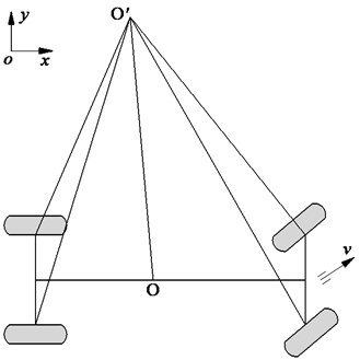
a) The structure model
b) The kinematics and dynamics model
It is assumed that the vehicle is moving steadily with a very small steering angle , thus, ≈ 1.
Both the lateral forces and acting on the front and rear wheels are determined based on the lateral stiffness of the front and rear wheels as follows:
where and are the lateral stiffness parameters of the front and rear wheels.
Based on the kinematics model of the vehicle in Fig. 1(b), the equations of the vehicle in the yaw direction are expressed by:
where is the vehicle mass and is the moment of inertia of the vehicle in the yaw direction.
Similarly, based on the kinematics model of the vehicle in Fig. 1(b), the deformation angle ; and the deformation angles of and are calculated and written by:
where , thus, .
By substituting Eq. (4) into Eq. (2), Eq. (2) is then rewritten by:
Therefore, Eq. (5) is used to compute the moving stability of the vehicle.
To evaluate the moving stability of the yaw rate at the centre of mass of vehicle, assuming that the vehicle moves with a constant speed and the deflection angle of the vehicle body is very small, we have:
By substituting Eq. (6) into Eq. (5), Eq. (5) is then rewritten by:
Eq. (7) can be written as follows:
By mathematically transforming Eq. (8), it is then rewritten by:
With , the correlation between and calculated from Eq. (9) is then described as follows:
Eq. (10) is simply written as follows:
where is defined as the correlation ratio between steering angle and yaw rate of the vehicle, and is defined as the factor of the moving stability of the vehicles.
From Eq. (11), we can see that the moving stability of the vehicle is affected by the geometrical and dynamic parameters of the vehicle. In order for the vehicle to move stably, the desired value of is 0 [7-8]. However, based on Eq. (11), the factor is strongly affected by the design and operating parameters of the vehicle, thus, to evaluate the moving stability of the vehicle, the characteristics of the and are then simulated and analyzed in Section 3.
3. The kinematics and dynamics model of vehicles
3.1. Effect of factor on the vehicle’s moving stability
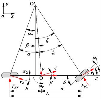
To evaluate the effect of the factor on the vehicle’s moving stability, the design parameters of the vehicle in Table 1, the input value of the steering angle of the front wheel in Fig. 2(a), and the vehicle moving speed of 72 km/h are used to simulate the characteristic of the vehicle yaw rate . The simulation results of the under various values of the factor [–0.002, –0.001, 01 0.001, 0.002] are shown in Fig. 2(b), respectively.
Table 1Design parameters of the vehicle
Parameters | Values | Parameters | Values |
(m) | 3.2 | m (kg) | 1200 |
(m) | 1.8 | (N/m) | 2.5×10⁴ |
(m) | 1.4 | (N/m) | 2.8×10⁴ |
Fig. 2The effect of the factor K on the vehicle’s yaw rate
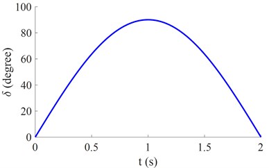
a) The steering angle of the front wheel
b) The characteristic of the yaw rate
In order for the vehicle to move stably, the desired value of is 0 [7-8]. With 0, Eq. (11) is then rewritten by or , and this is the ideal characteristic curve of the vehicle moving stability under the change of the steer angle of the front wheel . With both values of 0 and 0, the characteristic curve of , the more the vehicle’s characteristic curve deviates from the ideal curve of 0, thus, the vehicle moving stability is reduced. To get the value of 0 is very difficult because depends on the design and dynamic parameters of the vehicle, thus, the effect of the design parameters of the vehicle is evaluated in Sections 3.2 and 3.3.
3.2. Effect of operating parameters on the vehicle's moving stability
The operating parameters including the vehicle moving speed [40, 60, ..., 140, 160] km/h, the lateral stiffness parameters of the front and rear wheels [0.2, 0.4, ..., 1.2, 1.4] ×[, ], and the vehicle mass [0.2, 0.4, ..., 1.2, 1.4] are simulated to evaluate the vehicle moving stability. The simulation results have been plotted in Figs. 3(a), 3(b), and 3(c), respectively.
Fig. 3The effect of the operating parameters on the vehicle on the vehicle’s yaw rate
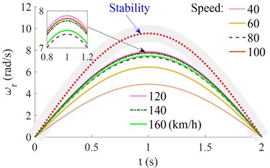
a) The effect of vehicle moving speed
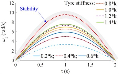
b) The effect of and
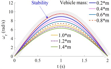
c) The effect of the vehicle mass
With the change of the vehicle moving speed , Fig. 3(a) shows that the characteristic curve of the vehicle’s yaw rate is near the ideal characteristic curve with 120 km/h, the characteristic curve of the vehicle’s yaw rate is always reduced when the increase or reduction of . This means that the vehicle moving stability is also reduced and strongly depended on the vehicle moving speed.
With the change of the lateral stiffness parameters of the front and rear wheels, Fig. 3(b) shows that when the lateral stiffness of the front and rear wheels is increased, the characteristic curve of the vehicle’s yaw rate is also near the ideal characteristic curve, especially at 1.4×, when the lateral stiffness of the front and rear wheels is reduced, the deviation of the vehicle's yaw rate is also increased compared to the ideal characteristic curve, thus, the vehicle moving stability is reduced. To enhance the moving stability and safety of the vehicle, the lateral stiffness of the front and rear wheels needs to be increased, this means that the air pressure of the front and rear wheels should be ensured.
Similarly, with the change of the vehicle mass, Fig. 3(c) shows that when the characteristic curve of the vehicle’s yaw rate is near the ideal characteristic curve when the vehicle mass is reduced, especially at 0.2×. This can be due to the centrifugal force of the vehicle being reduced with the reduction of the mass of the vehicle, thus, the vehicle moving stability is increased. Conversely, the vehicle moving stability is reduced with the increase of the vehicle mass.
3.3. Effect of geometrical parameters on the vehicle's moving stability
The design parameters including the vehicle length [0.5, 0.6, ..., 1.1, 1.2] ×(m) and [0.85, 0.90, ..., 1.05, 1.10] × (m) are also simulated to evaluate the vehicle moving stability. The simulation results are shown in Figs. 4(a) and 4(b).
Fig. 4The effect of the geometrical parameters on the vehicle’s yaw rate
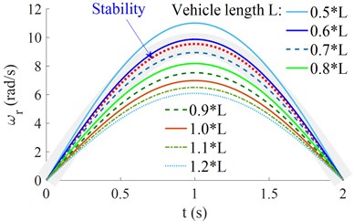
a) The effect of vehicle length
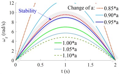
b) The effect of the longitudinal distance
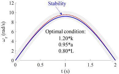
Fig. 5Optimization of the design parameters of the vehicle
With the change of the vehicle length , Fig. 4(a) shows that when the 0.5× < < 0.8×, the characteristic curve of the vehicle’s yaw rate is near the ideal characteristic curve, this means that the vehicle moving stability is good. Conversely, with ≥ 0.8× or ≤ 0.5×, the characteristic curve of the vehicle's yaw rate is always reduced, thus, the vehicle moving stability is also reduced. Similarly, with the change of longitudinal distance , the characteristic curve of the vehicle’s yaw rate is near the ideal characteristic curve when the longitudinal distance = 0.95×. Thus, both the and a significantly affect the vehicle moving stability. To enhance the vehicle moving stability, the design parameters of the and need to be chosen by 0.5× < < 0.8× and 0.95×.
With the optimal parameters of the lateral stiffness parameters of the front and rear wheels 1.20×, the vehicle length 0.8×, and the longitudinal distance 0.95×, the simulation result in Fig. 5 shows that the characteristic curve of the vehicle's yaw rate is near the ideal characteristic curve, thus, these optimal parameters can be chosen to design and control the vehicle moving stability.
4. Conclusions
The operating parameters of the vehicle greatly affect the vehicle moving stability. To enhance the vehicle moving stability, the lateral stiffness parameters of the front and rear wheels should be increased while the vehicle mass needs to be reduced in the operating condition of the vehicle.
The vehicle length and the longitudinal distance significantly affect the vehicle moving stability. In the design process of vehicles, the vehicle length should be reduced and the longitudinal distance of should be distributed by 0.95× to improve the vehicle moving stability.
Due to the mass and speed of the vehicle can be changed in the operating process, thus, they are difficult for control to enhance the vehicle moving stability. To solve this issue, the parameters of , , , , and should be optimized in the design process of vehicles.
The research results not only contribute to the existing body of knowledge on the moving stability of vehicles but also can provide an important reference of the theoretical research and numerical simulation approach of the dynamic model of vehicles.
References
-
V. Nguyen, Y. Hu, and Y. Ye, “Vibration research of heavy trucks. Part 1: sensitivity analysis of dynamic parameters on ride comfort,” Journal of Mechanical Engineering, Automation and Control Systems, Vol. 1, No. 2, pp. 114–123, Dec. 2020, https://doi.org/10.21595/jmeacs.2020.21813
-
V. Nguyen, Y. Ye, and Y. Hu, “Vibration research of heavy trucks. Part 2: optimization of vehicle dynamic parameters,” Journal of Mechanical Engineering, Automation and Control Systems, Vol. 1, No. 2, pp. 124–133, Dec. 2020, https://doi.org/10.21595/jmeacs.2020.21814
-
X. Meng, L. Ning, Y. Xie, and V. W. Wong, “Effects of the connecting-rod-related design parameters on the piston dynamics and the skirt-liner lubrication,” Proceedings of the Institution of Mechanical Engineers, Part D: Journal of Automobile Engineering, Vol. 227, No. 6, pp. 885–898, Jun. 2013, https://doi.org/10.1177/0954407012464025
-
V. Nguyen, R. Jiao, and J. Zhang, “Control performance of damping and air spring of heavy truck air suspension system with optimal fuzzy control,” SAE International Journal of Vehicle Dynamics, Stability, and NVH, Vol. 4, No. 2, pp. 179–194, Feb. 2020, https://doi.org/10.4271/10-04-02-0013
-
B. Kasemi, A. G. A. Muthalif, M. M. Rashid, and S. Fathima, “Fuzzy-PID controller for semi-active vibration control using magnetorheological fluid damper,” Procedia Engineering, Vol. 41, pp. 1221–1227, 2012, https://doi.org/10.1016/j.proeng.2012.07.304
-
V. Nguyen et al., “Performance analysis of semi-active hydraulic system of the off-road vibratory roller cab using optimal fuzzy-PID control,” Journal of Southeast University, Vol. 35, pp. 399–407, 2019, https://doi.org/10.3969/j.issn.1003-7985.2019.04.001
-
Dũng Huỳnh Phi, Vehicle Dynamics: Theory and Application. USA: Springer New York, 2005.
-
H. Pacejka, Tyre and Vehicle Dynamics. Oxford: Butterworth-Heinemann, 2002.
-
W. Milliken and D. L. Milliken, “Race Car Vehicle Dynamics,” Society of Automotive Engineers, Warrendale, 1994.
-
G. Mastinu and E. Battistini, “The influence of limited-slip differentials on the stability of rear-wheel-drive automobiles running on even road with dry surface,” International Journal of Vehicle Design, Vol. 14, No. 2, pp. 166–183, Jan. 1993, https://doi.org/10.1504/ijvd.1993.061832
-
H. Huchtkoetter and H. Klein, “The effect of various limited-slip differentials in front-wheel drive vehicles on handling and traction,” International Congress and Exposition, Vol. 1154, pp. 131–141, Feb. 1996, https://doi.org/10.4271/960717
-
S. Motoyama, H. Uki, K. Isoda Manager, and H. Yuasa Manager, “Effect of traction force distribution control on vehicle dynamics,” Vehicle System Dynamics, Vol. 22, No. 5-6, pp. 455–464, Jan. 1993, https://doi.org/10.1080/00423119308969043
-
S. Dieter, H. Manfred, and B. Roberto, Vehicle Dynamics Modeling and Simulation. Springer-Verlag Berlin Heidelberg, Germany, 2014.
-
S. Frank et al., “Tractor semi-trailer stability objective performance test research-roll stability,” National Highway Traffic Safety Administration, 2011.
-
B. A. S. Gill, M. Sehdev, and H. Singh, “Four-wheel drive system: architecture, basic vehicle dynamics and traction,” International Journal of Current Engineering and Technology, Vol. 8, No. 2, pp. 361–366, Apr. 2018, https://doi.org/10.14741/ijcet/v.8.2.28
-
Zhou Shuwen and Zhang Siqi, “Study on Tractor Semi-Trailer Roll Stability Control,” Vol. 8, pp. 238–242, 2014.
-
P. Osinenko and S. Streif, “Optimal traction control for heavy-duty vehicles,” Control Engineering Practice, Vol. 69, pp. 99–111, Dec. 2017, https://doi.org/10.1016/j.conengprac.2017.09.010
-
R. He, C. Sandu, M. N. Shenvi, H. Mousavi, J. Carrillo, and J. E. Osorio, “Laboratory experimental study of tire tractive performance on soft soil: Towing mode, traction mode, and multi-pass effect,” Journal of Terramechanics, Vol. 95, pp. 33–58, Jun. 2021, https://doi.org/10.1016/j.jterra.2021.02.001
-
D. Vieira, R. Orjuela, M. Spisser, and M. Basset, “Longitudinal vehicle control based on off-road tire model for soft soil applications,” IFAC-PapersOnLine, Vol. 54, No. 10, pp. 304–309, 2021, https://doi.org/10.1016/j.ifacol.2021.10.180
About this article

This research was supported by Open Fund Project of Hubei Key Laboratory of Intelligent Transportation Technology and Device, Hubei Polytechnic University, China (No. 2021XZ107).
