Abstract
Taking the copper conductor vertical barrel as the research object, the process flow principle of the packaging system of the copper conductor vertical barrel is described, the mechanism that meets the positioning of the inner hole is proposed. The transmission and kinematics characteristics of the mechanism under different rod sizes are analyzed. The optimal size of the kinematic parameters of the mechanism is solved using the MATLAB optimization toolbox, the size of each member is determined for further determine the specifications and dimensions of the original moving parts to provide a basis for the selection of the original moving parts.
Highlights
- The process flow principle of the packaging system of the copper conductor vertical barrel is described.
- The mechanism that meets the positioning of the inner hole is proposed.
- The transmission and kinematics characteristics of the mechanism under different rod sizes are analyzed.
- The optimal size of the kinematic parameters of the mechanism is solved using the MATLAB optimization toolbox.
- The size of each member is determined for further clarify the specifications and dimensions of the original moving parts.
- A basis for the selection of the original moving parts is provided.
1. Introduction
For product transportation, packaging technology mainly includes traditional cardboard box packaging, stretch film packaging, heat shrink film packaging and cold stretch sleeve packaging [1-3]. The integrity of the product in the transportation process is an important way to reduce the cost of the enterprise. Through the use of advanced packaging technology, the quality of the product is guaranteed, the packaging efficiency is improved, and the company brings economic benefits [4, 5]. The stretched film has high transparency, low squeezing force, high strength and good tear resistance. The cold stretch casing film packaging has the advantages of high work efficiency, ensuring the safety and reliability of the goods, and good visual effects [6-8]. In addition, the film packaging technology has a waterproof and dustproof packaging effect, which is especially suitable for the packaging of cables and plastic films, and is widely, used in construction, chemical, food and other industries [9-11].
For the process of cold stretch wrap film packaging, the main processes include tray loading, film unloading, film stretching, film wrap, and material unloading [12-14]. In the loading process, in order to ensure the integrity of the packaging film and good physical protection performance, accurate positioning of the goods loaded on the pallet is required [15-17]. For vertically placed cylindrical materials, the outer surface is in direct contact with the stretched film, and the inner surface is used for centering [18-20]. Currently, the medium and small-sized cylindrical materials mainly use the stretch film process, and there are few studies on the vertical placement of larger-sized cylindrical materials and the vertical centering.
2. Composition principle of cold stretch film system of vertical barrel
Wire and cable products need to meet strict packaging requirements due to their own attributes, sales requirements and circulation requirements. As a metal product that is easily oxidized, cables are also affected by light and moisture, which can cause material deterioration or damage. The packaging of materials is directly related to product quality. At the same time, today's consumer market is saturated; consumers will also consider the beauty and environmental protection of product packaging when choosing products. The quality of product packaging directly affects product sales. In addition, the product has to go through many links of transportation, handling, storage, etc. from the factory to the user, which requires that the packaging method should meet the convenience of handling and transportation. The above requirements fully verify the necessity of packaging.
Traditional wire and cable product packaging is mainly wood, because wood is easy to process and low in cost. With the improvement of human environmental protection awareness and new product packaging requirements, packaging forms have changed. As a new type of packaging material, stretch sleeve film, Because of its good protection performance, superior cost and efficiency, superior appearance transparency, and outstanding advantages in weight and environmental protection, its share in the packaging field is increasing. In the cable industry, in order to ensure the integrity of the product during transportation, higher requirements are put forward for the packaging of barrel-shaped materials.
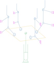
Fig. 1Schematic diagram of copper conductor vertical barrel
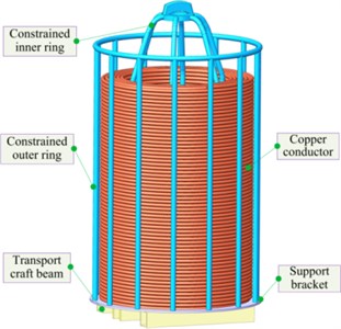
As shown in Fig. 1, the copper conductor vertical barrel is composed of a transportation process beam, a tray, a copper conductor, a restrained inner ring and a restrained outer ring. The transportation process beam can be used for the AGV forklift to lift or put down the vertical barrel to realize the transportation between different stations. The tray, the restrained outer ring and the restrained inner ring can limit the radial and axial movement of the copper conductor, and also protect the copper conductor from deformation due to external forces. Taking into account the properties of copper conductor products, sales and circulation needs, the copper conductor vertical barrel is now packaged with stretch film, that is, the stretch film is wrapped on the outside of the restraining outer ring to complete the packaging. At present, the vertical drum bagging method adopts manual bagging. Because the radial size of the copper conductor vertical drum is 1070 mm, and the axial size is 1980 mm, the cost of manual bagging is high and the packaging quality is poor. Unsightly and easy to fall off the bag. The covering mechanism is now used to cover the copper conductor vertical barrel, which can realize fast, efficient and high-quality packaging.
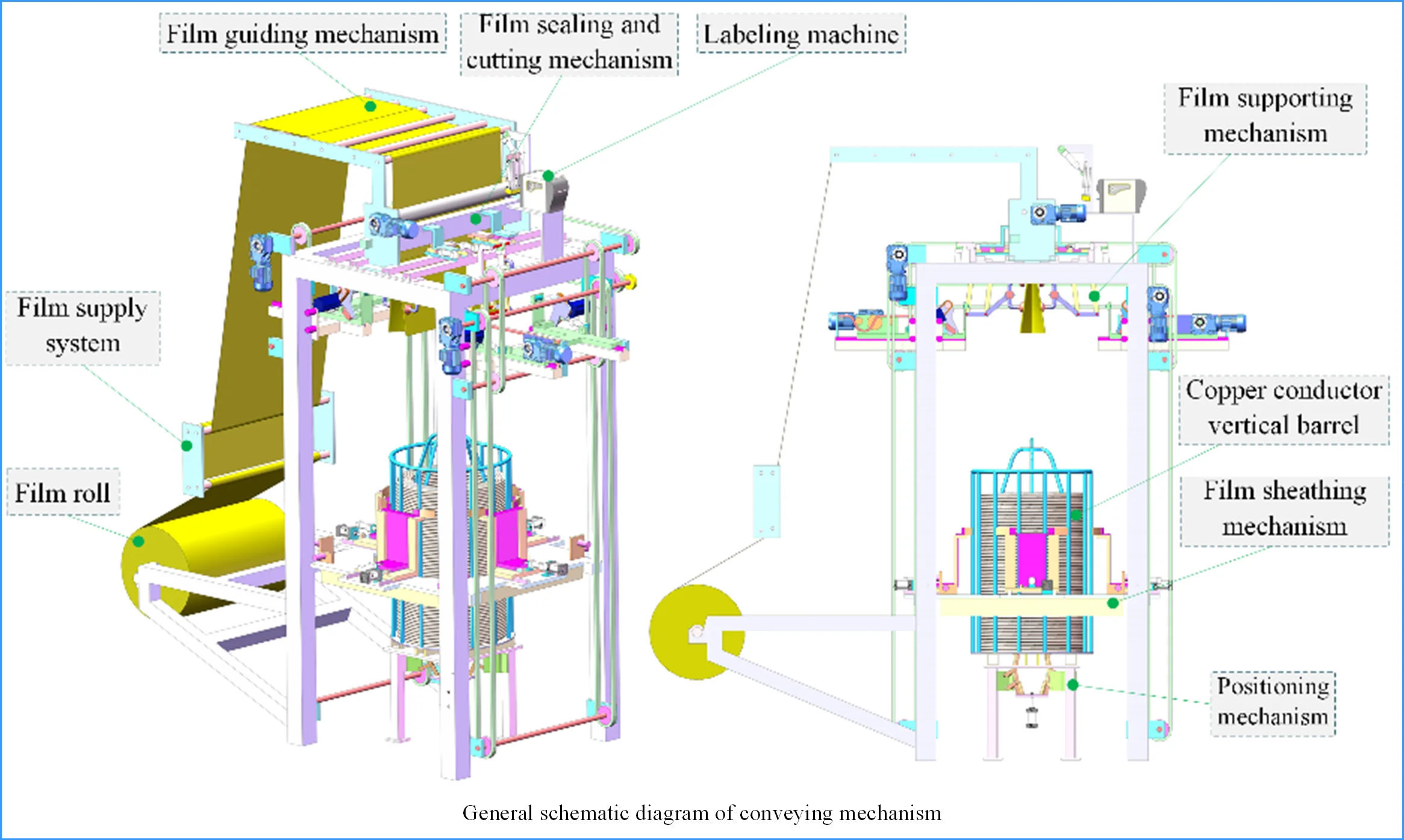
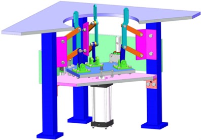
The cold drawing sleeve film system of copper conductor vertical barrel is composed of several mechanisms. As shown in Fig. 2, the system is composed of membrane sheathing mechanism, vertical barrel positioning mechanism, membrane supporting mechanism, membrane guiding mechanism, membrane sealing and cutting mechanism, etc. The finished film roll is pulled out of the film by the film pulling mechanism, runs to the upper end of the system through the film guiding mechanism, and the film supply mechanism stops working. The labeling mechanism prints relevant product information and pastes it on the stretched film surface. The film supply system continues to work, the vacuum sucker in the film supporting mechanism absorbs the film, the action of the mechanism lever group converts the film from line shape to surface shape, and the planar robot in the film covering mechanism converts the formed surface shape film into round shape. The film supply mechanism continues to work, when the film length reaches the specified length, the film supply mechanism stops working, and the sealing and cutting mechanism seals the film by heating and cuts off the film. The membrane sheathing platform moves downward to wrap the molded membrane downward on the vertical barrel, the membrane sheathing mechanism is separated from the membrane, and the membrane is tightly attached to the outer side of the vertical barrel under the action of its own contraction, thus completing the membrane sheathing process.
Fig. 2General schematic diagram of conveying mechanism

3. Overall design of vertical barrel positioning component
In the process of bagging the vertical barrel, due to the constraints of the performance parameters such as the cracking elongation, elongation ratio and tension ratio of the stretched film, as well as the errors in the conveying process, in order to ensure the good packaging effect, the allowable position error of the vertical barrel at the bagging station is only ±10 mm, so it is necessary to axially position the vertical barrel to meet the packaging requirements.
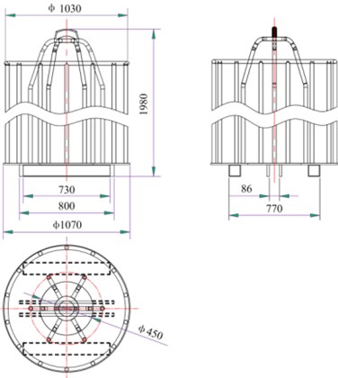
As shown in Fig. 3, the outer dimension of the copper conductor vertical barrel is 1070 mm, the height is 1980 mm, and the inner hole of the tray is 450 mm. The square steel at the bottom of the tray is used to support the vertical barrel and provide the necessary space for AGV forklift truck to work. The weight of the vertical barrel when it is full is 2.0T during the positioning process, the radial positioning is realized by overcoming the friction between square steel and bagging station.
Considering the errors in loading, supporting and discharging materials and the high requirements of the bagging station for the positioning of the copper conductor vertical barrel, a centering mechanism is set at the bagging station. In the process of covering film, the outer side of the whole material cylinder needs to be covered with film. If excircle positioning is used, it is not conducive to sheathing film and may even destroy the film. If the inner hole is used for positioning, the membrane sheathing process will not be disturbed. And the inner circle is not easily deformed by external load, and the positioning accuracy is high. Therefore, centering is completed by inner hole positioning.
Because the bottom of the copper conductor vertical barrel is provided with a beam passing through the axis of the circular hole, and the vertical barrel has a large mass, when three groups of bar mechanisms are used to realize the centering action, the requirements on the power source and bar members are high, and the centering accuracy is low and the stability is poor. In order to improve the stability and positioning accuracy in the centering process, four groups of bar members are used to realize the centering action.
Fig. 3Schematic diagram of copper vertical barrel size
As shown in Fig. 4, the inner hole centering mechanism of the mechanism consists of air cylinder, static platform, hinge platform, hinge support and rod group, etc. The air cylinder is fixed on the air cylinder mounting plate, and the piston is connected with the hinge platform through bolts to provide the hinge platform with lifting movement. The cylinder plate and the support are fixed on the frame through bolt connection. The hinge support is connected with the rod group, the lifting of the hinge platform drives the push rods 9 in the rod group to “shrink” or “expand”, and the expansion process is the process of positioning the copper conductor barrel. In the initial state, the cylinder piston is not extended, and the push rod 9 is in the “contracted” state, that is, the circle formed by the push rods in the four groups of rods has the smallest diameter, which is convenient for the vertical barrel to enter the station.
When the copper conductor vertical barrel enters the station, the air cylinder drives the hinge platform to move upwards, and the rod group moves under the action of the air cylinder. In this process, the diameter of the circle formed by four groups of push rods gradually increases, the push rods contact with the inner hole and apply load, and the vertical barrel moves stably under the action of external load. When the piston reaches the maximum stroke, the diameter of the circle formed by the four groups of push rods is the maximum. At this time, the four groups of rods are all in contact with the inner hole. That is, the inner hole is coaxial with the center of the rod group to complete the positioning.
4. Mechanism analysis of vertical barrel positioning component
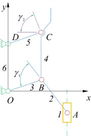
As shown in Fig. 5, the vertical barrel positioning mechanism consists of a prime Mover, a transmission part and an execution part. The prime Mover is an air cylinder, which is fixed on the frame, and its piston is locked with the hinge platform, that is, the air cylinder can directly control the lifting of the hinge platform. The transmission part consists of four groups of evenly distributed rods. Wherein the hinge support on the hinge platform is connected with the rod group, the lifting motion of the platform drives the rod group to move. The actuating part is a parallelogram-shaped connecting rod part, which realizes the vertical translation of the connecting rod by swinging the rod connecting the fixed hinge point, thus completing the centering process.
Fig. 4Schematic diagram of inner hole centering mechanism structure
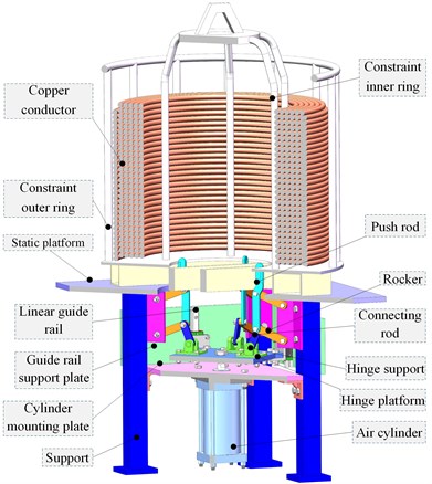
Fig. 5Schematic diagram of vertical barrel positioning mechanism
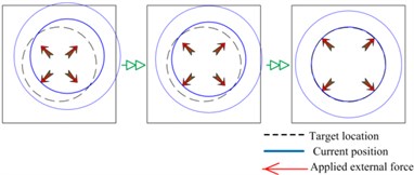
As shown in Fig. 6, during the positioning process of the copper conductor vertical barrel, four sets of evenly distributed push rods are driven by the cylinder to “expand” outwards to complete the centering. Due to the difference between the feeding position and reclaiming position of the AGV forklift, the vertical barrels will be randomly placed within a certain range. For different positions of the vertical bucket, the force applied by each push rod to the vertical bucket is different.
Fig. 6Positioning process analysis
It is calculated according to the limit position and the maximum force of the push rod, that is, the vertical barrel is at the limit position, and the centering process is completed by only one set of push rods. The full barrel mass of the copper conductor vertical barrel is 2.0 t, and the friction coefficient between the steel and the steel is 0.15, then the friction force of the vertical barrel during the centering process for = 3000 N.
That is, the minimum output force of the push rod is 3000 N.
The overall mechanism of the inner hole centering mechanism is shown in Fig. 5, and the motion characteristics of the four groups of rods evenly distributed in the circumferential direction are the same. The movement of a group of rods is studied separately. The movement diagram of a single group of rods is shown in Fig. 7. The mechanism is composed of three parts: the frame, the original moving part and the basic rod group. When the specific motion parameters of the original mover slider are given, the basic rod group has a certain motion.
Fig. 7Single group member motion diagram
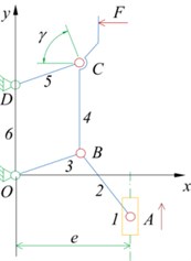
Fig. 8Slider-rocker mechanism movement diagram
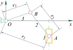
In order to facilitate the description of the motion characteristics and optimal design of the component, it is now defined as follows. For members , define the length of the member as , the vector value of the member is , lever the angle between the straight line and the counterclockwise direction of the x positive semi-axis is , lever the angular velocity and angular acceleration are , . For slider 1, the initial position, velocity, and acceleration of the slider are respectively , , , the offset distance is .
The movement diagram of the slider-rocker mechanism is shown in Fig. 8. The mechanism is composed of a slider 1, a connecting rod 2 and a rocker 3. The slider 1 is the driving member, the rocker 3 is the driven member and the up and down movement of the slider 1 is transformed into the reciprocating swing of the rocker 3. From the previous section, we can see that the sliders and rods the definition of content, the vector equation of the organization can now be established .
According to 8 and the closed vector polygon equation, the angular displacement matrix component of the mechanism is in the form:
Deriving Eq. (1) with respect to time t, the component form of the angular velocity equation of the mechanism is:
Derive Eq. (2) for time , and the component form of angular acceleration equation of the mechanism is:
According to the geometric relation and cosine theorem of Fig. 3, there are:
According to the actual space layout, the bar size is initially determined, 80 mm, 120 mm, 145 mm. Through MATLAB programming, the driving force of the prime Mover that meets the reasoning conditions can be solved. When –48.0683°, 40.2850° is set, then 6239.25 N. When the pressure p of the air source is 0.6 MPa, the cylinder diameter of the cylinder of the prime mover can be solved, so that the prime mover can be selected:
Therefore, the actual diameter d of the cylinder piston should meet the requirement of , and taking the cylinder with a diameter of 125.0 mm as driving cylinder meet the requirement.
5. Optimal design of single branch positioning mechanism
In order to further study the kinematic performance and dynamic performance of the mechanism, it is necessary to determine the size and position parameters of each component, and MATLAB optimization toolbox function can be used to deal with this problem. In the actual optimization design process, there are three main steps: first, establish the mathematical model of optimization, that is, determine the design variables, establish the objective function and determine the constraint conditions. Secondly, select the appropriate optimization function according to the actual problem, and finally carry out optimization calculation to determine the position and size parameters of each component.
The mutually independent quantities that are selected in the design process and finally must be determined are called design variables. In this mechanism, the length of each bar , , , , and the eccentricity of the slider are be quantified. For this institution, there are , . Therefore, the design variables can be expressed as:
The variable is a 5-dimensional, which belongs to a small-scale optimization design problem.
In practical application, the value of design variables is usually limited by many conditions, and the common area that meets all the constraints is called feasible area. By substituting the coordinates of each point in the feasible area into the objective function, we can get the solution that best meets the objective function, which is the optimal solution of design variables. Constraints can be divided into geometric constraints and performance constraints.
In this mechanism, the slider is the driving part and the rocker is the driven part. To avoid the “dead point” of the mechanism, the bar has no turnover movement, that is . The inequality constraints are written as:
In the optimization design of linkage kinematics, in order to obtain the best force transmission performance, it is required to select the best kinematics parameters, and the optimization design often establishes the objective function according to the kinematics parameters of the mechanism. As shown in Fig. 9, this mechanism consists of slider-rocker mechanism OAB and OBCD with planar linkage mechanism in series. In order to make the mechanism have good motion characteristics, the transmission angle of two mechanism elements , is greater than or equal to the allowable transmission angle . The mechanical structure transmits a large amount of power, so the allowable transmission angle is selected for 40°. The angle , is larger; the force transmission performance of the mechanism is the better. The transmission angle can be used as a performance constraint.
Wherein, the , should be satisfied 40°, and the constraint equation is obtained:
In the practical engineering application of the mechanism, the size of each bar is limited by the working space. The size requirement of existing component 3 is , the range of offset distance e is , the angle range of joystick OB is 40°. In order to avoid the mechanism “dead point”, the value range of connecting rod AB:
After sorting out, the constraint equation is as follows:
In addition, in the whole movement process of the mechanism, not only necessary to meet the above inequality constraints, but also to consider the bar length condition of the mechanism:
To sum up, Eqs. (6)-(17) constitute the constraint function of the optimal design of the bar, which constrains the value range of the design variables.
When the objective function is established, the optimal choice of the prime mover is taken as the objective, that is, the optimal cylinder block diameter is taken as the objective. As shown in Fig. 9, this mechanism is composed of slider-rocker mechanism OAB and planar linkage mechanism OBCD in series. When choosing the prime mover, the mechanism can have good force transmission performance by changing the component size. Considering the transmission performance of the mechanism, when the objective function is established, the driving force of the prime Mover is selected as an important index to evaluate the performance of the mechanism. Now fmincon function is used to optimize the actual problem.
Fig. 9Transmission angle of mechanism
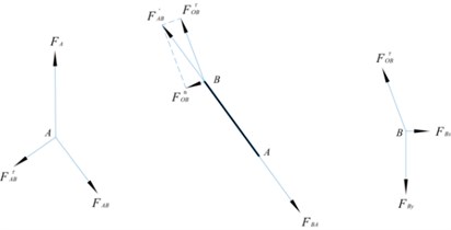
The force vector diagram of the whole system is shown in Figure 10, which is used to calculate the driving force of the slider , through the stress analysis of each bar:
Fig. 10Force vector diagram of mechanism
When using the optimization function, the objective function needs to be sorted into the minimum function and substituted into the design variable:
In the process of force transmission, the transmission angle of the rocker-slider mechanism OAB, it should also be as large as possible, and the objective function can be established:
In the calculation process, the objective function and fractions in Play an equivalent role, so the objective function can be omitted .
In summary, the objective function equation is:
The MATLAB optimization toolbox contains a series of optimization algorithms and modules that can be used to solve linear programming and quadratic programming, the maximum and minimum values of functions, nonlinear programming, multi-objective optimization, nonlinear least squares approximation and curves fitting, nonlinear system equations and large-scale problems with complex structures. According to the description in the previous section, the example standard form is a general constrained nonlinear objective programming problem:
Call the nonlinear programming function fmincon solver in MATLAB optimization toolbox to solve. Its use form is:
where, is the objective function.
The meaning of each parameter is as follows: is the optimal solution of the return objective function, is the function value of the return objective function at the optimal solution point, exit flag is an integer identifying the reason for the termination of the algorithm , in order to call the function file name of the multi-objective function, is the initial value of the variable, , are the coefficient matrix and constant vector of the linear inequality constraint, , are the coefficient matrix and constant vector of the linear equality constraint, , they are the lower bound vector and upper bound vector of the design variable , and nonlcon is the name of the function that defines the nonlinear constraint.
For this 5-dimensional multi-objective optimization problem, combined with the optimization mathematical model and optimization function, the objective function file, the constraint function file and the main file of the optimization design mathematical model are compiled. Run the program:
= [103.7809; 141.2830; 122.5435; –1.0471; 1.0471]
= 4621.21;
After iterative calculation, the optimal solution is obtained: 103.7809, 141.2830, 122.5435, –1.0471, 1.0471, and then transform it into a rounded solution based on the actual working conditions. Round up the solution as 105, 104, 120, at this time, –60.3509°, 60.9136°, 4621.21 N. When the air source pressure is 0.6 MPa, the bore d of the prime mover cylinder can be solved:
The standard cylinder can choose a cylinder with a bore of 100 mm. The rounding solution can meet the transmission angle requirements, at this time the mechanism has better force transmission characteristics, and the optimization results meet the requirements.
Taking the optimized rounded rod length and eccentricity as parameters, the mathematical model of the single-chain positioning mechanism is re-established, and the motion law of the connecting rod 4 in contact with the positioning surface is studied. Because the planar linkage mechanism OBCD constitutes a parallelogram mechanism, the movement law of linkage 4 and point B is the same.
Fig. 11Horizontal and vertical displacement curve of connecting rod 4
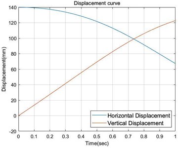
Fig. 12The horizontal and vertical speed curve of connecting rod 4
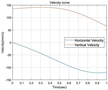
Fig. 13Horizontal and vertical acceleration curves of connecting rod 4
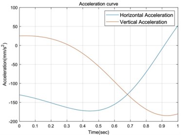
Fig. 14Schematic diagram of optimized organization
Now take the hinge point O as the coordinate origin, calculate the displacement, velocity and acceleration curves of point B in the horizontal and vertical directions respectively, that is, the movement law curve of connecting rod 4, as shown in Figs. 11-13.
After determining the size of each rod, build a three-dimensional model according to the rounded connecting rod size, as shown in Fig. 11. Where, 105, 140, 120, the cylinder only needs to select a cylinder with a cylinder diameter of 100 mm and a stroke of 150 mm to complete the centering process under the supply of 0.6 MPa air source. The allowable error of the centering mechanism is ±50 mm, that is, the centering process can be completed by the centering mechanism within the 50 mm range of the target position axis of the copper conductor vertical barrel. It provides conditions for bagging of vertical barrels.
6. Conclusions
This paper studies the inner hole positioning mechanism of the copper conductor vertical barrel, and optimizes the design of its rods in combination with actual problems, which has a guiding effect on the selection of the original moving parts. Through the analysis of the membrane system mechanism, the explanation of the principle of the positioning mechanism, the establishment of the mathematical model of the optimal design, the use of MATLAB software to solve the optimal size parameters of the mechanism, and the selection of the appropriate specifications of the cylinder, And the size ratio of the rods in the mechanism has certain guiding significance for actual engineering practice, and it provides a way of thinking for the optimization design of tandem rods and the selection of the original moving parts.
References
-
S. Seo and N. Kim, “Optimum design of the cored linear motor using experiment design,” Journal of Mechanical Science and Technology, Vol. 23, No. 8, pp. 2215–2223, Aug. 2009, https://doi.org/10.1007/s12206-009-0514-1
-
B. J. Zheng, “Green packaging materials and modern packaging design,” in Applied Mechanics and Materials, Vol. 271-272, pp. 77–80, Dec. 2012, https://doi.org/10.4028/www.scientific.net/amm.271-272.77
-
Z. Q. Li, “Research on simulation of kinematics and dynamics for planner six-bar mechanism based on MATLAB/Simulink,” in Applied Mechanics and Materials, Vol. 391, pp. 109–113, Sep. 2013, https://doi.org/10.4028/www.scientific.net/amm.391.109
-
Q. M. Fan and Y. H. Wu, “The multi-objective optimization design of a forklift steering mechanism,” Advanced Materials Research, Vol. 1049-1050, pp. 884–887, Oct. 2014, https://doi.org/10.4028/www.scientific.net/amr.1049-1050.884
-
R. Shefi and M. Teboulle, “Rate of convergence analysis of decomposition methods based on the proximal method of multipliers for convex minimization,” SIAM Journal on Optimization, Vol. 24, No. 1, pp. 269–297, Jan. 2014, https://doi.org/10.1137/130910774
-
K.-W. Kim, J.-W. Lee, H.-R. Kim, J.-S. Jang, and W.-S. Yoo, “Necessity of transient-state unwinding equation of motion for analyzing unwinding motion of a thin cable,” Nonlinear Dynamics, Vol. 80, No. 3, pp. 1565–1583, May 2015, https://doi.org/10.1007/s11071-015-1963-y
-
Y. Luo, W. Liu, and L. Wu, “Analysis of the displacement of lumped compliant parallel-guiding mechanism considering parasitic rotation and deflection on the guiding plate and rigid beams,” Mechanism and Machine Theory, Vol. 91, pp. 50–68, Sep. 2015, https://doi.org/10.1016/j.mechmachtheory.2015.04.007
-
O. A. Turkkan and H.-J. Su, “DAS-2D: a concept design tool for compliant mechanisms,” Mechanical Sciences, Vol. 7, No. 2, pp. 135–148, Jul. 2016, https://doi.org/10.5194/ms-7-135-2016
-
G. Hao and R. B. Hand, “Design and static testing of a compact distributed-compliance gripper based on flexure motion,” Archives of Civil and Mechanical Engineering, Vol. 16, No. 4, pp. 708–716, Sep. 2016, https://doi.org/10.1016/j.acme.2016.04.011
-
K. A. Tolman, E. G. Merriam, and L. L. Howell, “Compliant constant-force linear-motion mechanism,” Mechanism and Machine Theory, Vol. 106, pp. 68–79, Dec. 2016, https://doi.org/10.1016/j.mechmachtheory.2016.08.009
-
G. Rosati, S. Minto, and F. Oscari, “Design and construction of a variable-aperture gripper for flexible automated assembly,” Robotics and Computer-Integrated Manufacturing, Vol. 48, pp. 157–166, Dec. 2017, https://doi.org/10.1016/j.rcim.2017.03.010
-
N. Eqra, A. H. Abiri, and R. Vatankhah, “Optimal synthesis of a four-bar linkage for path generation using adaptive PSO,” Journal of the Brazilian Society of Mechanical Sciences and Engineering, Vol. 40, No. 9, pp. 1–11, Sep. 2018, https://doi.org/10.1007/s40430-018-1392-1
-
F. Ma and G. Chen, “Influence of non-ideal fixed-end constraints on kinetostatic behaviors of compliant bistable mechanisms,” Mechanism and Machine Theory, Vol. 133, pp. 267–277, Mar. 2019, https://doi.org/10.1016/j.mechmachtheory.2018.11.008
-
A. Beck and N. Guttmann-Beck, “FOM – a MATLAB toolbox of first-order methods for solving convex optimization problems,” Optimization Methods and Software, Vol. 34, No. 1, pp. 172–193, Jan. 2019, https://doi.org/10.1080/10556788.2018.1437159
-
N. Eqra, S. Taghvaei, and R. Vatankhah, “Optimal kinematic design of a single-DOF planar grasper based on metaheuristic optimization,” Journal of the Brazilian Society of Mechanical Sciences and Engineering, Vol. 41, No. 10, pp. 1–11, Oct. 2019, https://doi.org/10.1007/s40430-019-1923-4
-
E. Y. Hamedani and N. S. Aybat, “A primal-dual algorithm with line search for general convex-concave saddle point problems,” SIAM Journal on Optimization, Vol. 31, No. 2, pp. 1299–1329, Jan. 2021, https://doi.org/10.1137/18m1213488
-
E. R. Csetnek, “Continuous dynamics related to monotone inclusions and non-smooth optimization problems,” Set-Valued and Variational Analysis, Vol. 28, No. 4, pp. 611–642, Dec. 2020, https://doi.org/10.1007/s11228-020-00548-y
-
J.-H. Kang, K.-W. Kim, J.-W. Lee, Y.-J. Cho, and J.-S. Jang, “Development of a test method and experimental study on cable unwinding,” Proceedings of the Institution of Mechanical Engineers, Part C: Journal of Mechanical Engineering Science, Vol. 235, No. 15, pp. 2653–2667, Aug. 2021, https://doi.org/10.1177/0954406220954498
-
G. Wandosell, M. C. Parra-Meroño, A. Alcayde, and R. Baños, “Green packaging from consumer and business perspectives,” Sustainability, Vol. 13, No. 3, p. 1356, Jan. 2021, https://doi.org/10.3390/su13031356
-
Y. Li, B. Jiang, W. Li, J. Wang, and Y. Yang, “The chain microstructure and condensed structure of polyethylene resin used for Biaxially stretched film,” Journal of Applied Polymer Science, Vol. 138, No. 2, p. 49652, Jan. 2021, https://doi.org/10.1002/app.49652
-
A. Ghasemi, M. Shakeri, and S. A. S. Vanini, “A multi-objective optimization of energy absorption properties of thin-walled circular tube with combined bar extrusion under quasi-static axial loading: Experiments and numerical simulation,” International Journal of Mechanical Sciences, Vol. 180, p. 105691, Aug. 2020, https://doi.org/10.1016/j.ijmecsci.2020.105691
-
J. He, J. Li, Z. Sun, F. Gao, Y. Wu, and Z. Wang, “Kinematic design of a serial-parallel hybrid finger mechanism actuated by twisted-and-coiled polymer,” Mechanism and Machine Theory, Vol. 152, p. 103951, Oct. 2020, https://doi.org/10.1016/j.mechmachtheory.2020.103951
-
S. Henning and L. Zentner, “Analysis of planar compliant mechanisms based on non-linear analytical modeling including shear and lateral contraction,” Mechanism and Machine Theory, Vol. 164, p. 104397, Oct. 2021, https://doi.org/10.1016/j.mechmachtheory.2021.104397
-
P. Bilancia, S. P. Smith, G. Berselli, S. P. Magleby, and L. L. Howell, “Zero torque compliant mechanisms employing pre-buckled beams,” Journal of Mechanical Design, Vol. 142, No. 11, p. 11330, Nov. 2020, https://doi.org/10.1115/1.4046810
-
J.-S. Yi, F. Yumbla, E. Auh, M. Abayebas, T. A. Luong, and H. Moon, “Passive aligning of ribbon cable in sliding surface gripper for assembly task,” Journal of Mechanisms and Robotics, Vol. 13, No. 2, p. 02500, Apr. 2021, https://doi.org/10.1115/1.4048915
About this article

The authors would like to thank the Northeast Forestry University (NEFU), Heilongjiang Institute of Technology (HLJIT), and the Harbin Institute of Technology (HIT) for their support.
The research subject was supported by the Doctoral Research Startup Foundation Project of Heilongjiang Institute of Technology (Grant No. 2020BJ06, Yongmei Wang, HLJIT), the Natural Science Foundation Project of Heilongjiang Province (Grant No. LH2019E114, Baixue Fu, HLJIT), the Basic Scientific Research Business Expenses (Innovation Team Category) Project of Heilongjiang Institute of Engineering (Grant No. 2020CX02, Baixue Fu, HLJIT), the Special Project for Double First-Class-Cultivation of Innovative Talents (Grant No. 000/41113102, Jiafu Ruan, NEFU), the Special Scientific Research Funds for Forest Non-profit Industry (Grant No. 201504508), the Youth Science Fund of Heilongjiang Institute of Technology (Grant No. 2015QJ02), and the Fundamental Research Funds for the Central Universities (Grant No. 2572016CB15).
