Abstract
The objective of this study is to provide a simplified worksheet based on the Total Equivalent Temperature Difference (TETD) Approach to estimate a building’s cooling load under Iraqi climate conditions. The heating, ventilation and air conditioning (HVAC) system was applied to scientific laboratories at the College of Engineering, University of Warith Al-Anbiyaa, Karbala, Iraq. The study estimates the cooling load of the building, which consists of 10 zones. Cooling load elements such as ventilation, lighting, walls, floors, roofs, windows, infiltration, and human factors were considered. The worksheet provides an appropriate alternative for easy and fast prediction within Iraq's climate conditions.
1. Introduction
A 48 % increase in global energy consumption is predicted from 2012-2040 [1]. Energy consumption in developing countries such as the Middle East, South America, and Africa is expected to increase by about 3.2 % by the year [2]. as a result, many techniques have been reestablished in order to reduce or eliminate the need for cooling, heating, and mechanical ventilation, thereby decreasing overall energy consumption. Total energy saving potential can be increased through the optimum use of building design [3]. Exact calculations of the cooling and heating loads of buildings are essential to predict needed equipment to achieve comfortable operation, minimize energy consumption, and get good air circulation all around conditioned space. Designers must understand the activity and comfort needs of any conditioned space [4, 5]. well as some information about the construction of the building and whether it is appropriate for the specified use of the function or not.
It is necessary to understand the building application and, in most buildings, the function of each space must be known. This will affect the occupants of the place in terms of comfort, level of activity or potency, humidity, temperature, and ventilation requirements. Designers must have all the answers to these points and many other questions before they can calculate the thermal load of a building and choose a suitable HVAC system. Calculated load determines the correct selection of various equipment like chillers or terminal units, boilers, cooling towers, and pumps.
Air-conditioning provides a comfortable atmosphere suitable for a building function and for the comfort of human beings or for the proper performance of some industrial operations [6]. Sen et al. [7] used the CLTD Method to estimate the cooling load of a classroom in an academy where it produced an easier manual calculation of the thermal load and very good and acceptable results were obtained when presented in a simple worksheet in Haryana. Muhammad et al. [8] compared hand calculations using the CLTD method and results from an hourly analysis program (HAP) for building cooling loads in Erbil Polytechnic University/Refrigeration and Air-conditioning Engineering Department.
Al-Rabghi et al. [9] expected the hourly thermal load for many types of partitions, such as walls, ceilings, and windows, by using the transfer function method (TFM) and compared the results with the HAP program, so the agreement was acceptable. Westphal et al. [10] estimated the thermal load of industrious buildings using the Transfer Function Method (TFM) and ran the calculations based on ASHRAE [11]. Their method produced reliable data for cases with a low mass envelope. However, a thermal inertia effect on the annual loads was observed in their study.
Andersson et al. [12] computed the cooling and heating loads of residential buildings in many directions using the commercial software BLAST. the results showed that the total loads for the north direction were higher than the south. However, in the extreme southern latitudes of the U.S, the converse was true. Shariah et al. [13] investigated the effect of building external surfaces on thermal loads in Amman and Aqaba, Jordan, using the Transient System Simulation Tool TRNSYS. Their study showed that for insulated buildings, the total energy load was reduced by 26 % in Amman and 32 % in Aqaba. Virendra et al. [14] used the CLTD method to determine the sensible cooling load estimation for evaporative cooling by hand calculations, and the results were compared with the well-known Carrier program, HAP 4.5, for a three-story shop building. It was observed a dissimilarity between the two studies because hand calculations are based on the peak value of the day while the Carrier program gives a weighted average value.
Yadav et al. [15] calculated the cooling loads for a classroom located in Ghaziabad, India during summer using the cooling load temperature difference method (CLTD) and based on ASHRAE and CARRIER [11, 16], obtaining reliable data. Duanmu et al. [17] calculated a building's thermal load using an Hourly Cooling Load Factor Method (HCLFM) that has shown fast and reliable estimation of the thermal load calculation in urban energy planning. Gaadhe et al. [18] used the transfer function method as a one-step technique, which was first described in ASHRAE [11] to determine the cooling load of a reading hall. This method is called the “Total Equivalent Temperature Differences (TETD) method”. Felix et al. [19] predicted the hourly and daily average thermal loads for a building based on the Transfer Function Method (TFM). in their study, a worksheet that helps with cooling load evaluation in Ghana was presented. the obtained results were compared with data from commercial software and good agreement was reported.
Full air-conditioning systems involve adjusting the indoor environment in terms of temperature, air motion, humidity, air purity, and noise within factors determined by design specification. Thus, to achieve satisfactory results, equipment of the appropriate size needs to be chosen according to the hourly peak load calculations [20]. in this work, a building that consists of 10 zones was selected to develop a cooling load estimation sheet for hot weather conditions in Iraq by applying the TETD method. External and internal cooling load elements such as people, walls, floors, glasses, lighting, infiltration, and ventilation heat gain were included.
2. Components of thermal load
The first basic step in designing any HVAC system is to calculate the cooling load of the building. the current cooling load estimation method is based on the heat transfer of all-air systems found in ASHRAE [11].
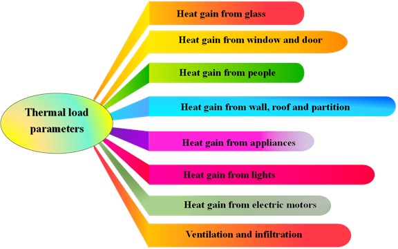
The complexity of the transfer of heat to the building was evaluated, considering changes in indoor and outdoor conditions. the external loads are caused by ventilation and solar radiation through the structure, such as walls, ceilings, windows, and doors. the internal loads are evaluated based on the number of occupants and their activity levels, appliances, and lighting as shown in Fig.1. the heat gain from internal heat sources can be assumed to be constant. However, there are significant changes in the cooling load of an externally loaded building in the city of Karbala, Iraq, because the ambient conditions are largely variable during any given day.
Fig. 1Thermal load parameters
3. Estimation method
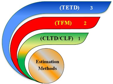
Generally, three different methods (Fig. 2) are used to calculate the cooling loads of buildings, which are the Transfer Function Method (TFM), the Cooling Load Temperature Difference or Cooling Load Factors (CLTD/CLF), and the Total Equivalent Temperature Difference (TETD) [21]. the first method produces the most accurate results, but because of its complexity, it requires advanced database and programming. the CLTD was derived to simplify the calculations of the TFM, and it has shown reasonably accurate predictions in terms of the total heat gains through walls and roofs. However, the last method (TETD) is used in our calculations because it takes into account both conduction heat gain through the walls and roofs as well as the effects of solar energy impinged on the structures' external surfaces [9].
Fig. 2Methods of load calculation
4. Accuracy and reliability of various calculation methods
Each cooling / heating calculations has a number of advantages and disadvantages. Simplicity and accuracy are two mutually exclusive aims that must be met. if a procedure is considered easy, its accuracy is questioned, and vice versa.
Internal heat gain calculations are included in the handbooks. Such tables, however, are incomplete. for example, for equipment not specifically referenced in the tables, just a limited amount of information is provided. Occasionally, recommendations are made to consume 25 % to 50 % of the nameplate power consumption, with the ultimate amount left to the designer's opinion. at other instances, it is critical to accurately estimate the occurrence, for example, the frequency with which equipment is used is critical in determining the heat gain. This example of internal heat gain demonstrates that when considering accuracy, it is not only the method (simple vs. sophisticated) that matters, but also the uncertainties in the input data [11].
There are significant uncertainties in the input data necessary to calculate cooling loads. This is mostly owing to the unpredictable nature of occupancy, human behavior, exterior weather variations, the lack of and variation in heat gain data for current equipment, and the introduction of new building goods and HVAC equipment with unknown parameters. These generate uncertainties that far outweigh the inaccuracies generated by simpler methods. as a result, the additional time/effort necessary for the more complex calculation methods would be ineffective in terms of improving the accuracy of the findings if the input data has a high degree of uncertainty. Otherwise, simplified methods would almost certainly have a comparable rate of precision [14].
5. Theoretical analysis
In Iraq's climate, temperature changes extensively during the day in summer or winter, where differences of about 25 °C are recorded between daytime and night time. This requires significant changes in the amount of cooling and heating needed to keep a room in comfortable conditions on any given day. to achieve indoor human comfort conditions during the summer, a dry bulb temperature (DBT) of 23 °C to 26 °C with a relative humidity (RH) of approximately 50 % is required. a bulb temperature of 24 °C and a relative humidity of 50 % were selected in the current study to calculate the cooling loads of the University of Warith Al-Anbiyaa scientific laboratories, which are considered the recommended indoor design conditions.
The ambient design conditions were selected from published weather data recorded at the location of interest. the outdoor design conditions of Karbala, Iraq are 46 °C DBT and 24 °C WBT during the summer, with an 18.9 °C daily range (for the month of August). Hand calculations were carried out for all laboratories using the following steps [11].
(1) Solar heat gain from Glass:
where is 1.7 for steel sash.
(2) Solar transmission from window and door:
(3) Solar and transmission Gain for Walls:
(4) Heat transmission from partition:
(5) Solar and transmission gain from:
– Exposed roof:
– Unexposed roof and unconditioned space above:
– Roof or floor Kitchen or boiler room below:
(6) Heat gain from people:
– Sensible heat gain:
– Latent heat gain:
where 1 for men, 0.8 women and 0.75 for children.
(7) Heat gain from appliances:
– Sensible heat gain:
– Latent heat gain:
where 0.5 for positive exhaust.
(8) Heat gain from lights:
where: 1.25 for fluorescent so the light power is to be assigned by electrical engineering, or it may be assumed 20 W/m2 for floor area.
(9) Heat gain from electric motors:
(10) Infiltration:
– Depending on windows or doors area:
– Depending on the crack length:
where , While for double hung window or door .
(11) Ventilation:
– Outdoor air ventilation depending on the number of people:
– Outdoor air ventilation depending on the floor area:
– Outdoor air sensible heat (OASH):
– Outdoor air latent heat (OALH):
– Outdoor air total heat (OATH):
(12) Room Sensible Heat (RSH) = Σ Eqs. (1, 2, 3, 4, 5a, 5b, 6a, 7a, 8 and 9).
(13) Room Latent Heat (RLH) = Σ Eq. (6b and 7b).
(14) Room Total Heat (RTH) = RSH + RLH.
(15) Total Sensible Heat (TSH) = RSH + OASH.
(16) Total Latent Heat (TLH) = RLH + OALH.
(17) Grand Total Heat (GTH) = TSH + TLH.
(18) Total load in TON = GTH / 3516.
6. Results and discussion
This work covers the calculation of the thermal loads of one of the buildings of the scientific laboratories located at the University of Warith Al-Anbiyaa, Iraq. the floor plan of the building is shown in Fig. 3. the building consists of one floor and has a total area of 1481.7 square meters. the building is located in the south-eastern part of the university site and consists mainly of walls and a metal structure that is double-insulated.
The calculation of thermal loads in the conventional way was done by means of theoretical equations and tables. the simplified worksheet of the cooling load calculation steps of the Engineering Workshops is shown in Table 1.
Table 1Simplified worksheet for engineering workshops room
Cooling load | Building: laboratories | Room name: engineering workshops | Room No. 1 | |||||||||
Indoor design condition | 24 °C DBT | 17 °C WBT | 50RH % | |||||||||
Outdoor design condition | 46 °C DBT | 24 °C WBT | 15RH % | |||||||||
Month: July | Peak Time: 3 PM | City: Karbala, Iraq | Lat. 33 | |||||||||
Steps | ||||||||||||
Solar gain windows: | ||||||||||||
Glass | 1 | Q | Sol HG. | A | F | |||||||
/window | = | 570 | × | 4.455 | × | 1.7 | = | 4316.89 | ||||
/window | = | 328 | × | 16.5 | × | 1.7 | = | 9200.4 | ||||
Transmission windows: | ||||||||||||
2 | W/m2 °C | A | ∆t | |||||||||
window | = | 6.42 | × | 4.455 | × | 22 | = | 629.22 | ||||
door | = | 2.9 | × | 12 | × | 22 | = | 765.6 | ||||
Solar and transmission gain: | ||||||||||||
Walls, Floor and Roof | 3 | W/m2 °C | A | ∆te | ||||||||
/Wall | = | 2.22 | × | 39.6 | × | 16.94 | = | 1489.22 | ||||
/Wall | = | 0.590 | × | 29.7 | × | 16.94 | = | 296.84 | ||||
/Wall | = | 2.22 | × | 98.4 | × | 19.95 | = | 4358.03 | ||||
/Wall | = | 0.590 | × | 73.8 | × | 19.95 | = | 868.66 | ||||
4 | Partition | = | 2.22 | × | 26.24 | × | 3 | = | 174.7 | |||
Partition | = | 0.590 | × | 19.68 | × | 3 | = | 34.83 | ||||
5 | Roof | = | 0.590 | × | 223.13 | × | 13 | = | 1711.4071 | |||
Floor | = | 1.3 | × | 223.13 | × | 13 | = | 3770.897 | ||||
Heat gain: | ||||||||||||
People | No. | Sen. HG | F | |||||||||
6a | Sensible | = | 25 | × | 170 | × | 1 | = | 4250 | |||
6b | Latent | = | 25 | × | 255 | × | 1.25 | = | 7968.75 | |||
Ap | 7a | Sensible | = | 4000 | + | 1500 | + | 950 | = | 6450 | ||
7b | Latent | = | – | × | – | × | – | = | ||||
Light | 8 | No. | W | F | ||||||||
Light | = | 8 | × | 40 | × | 1.25 | = | 400 | ||||
9 | Elec. Motor | = | – | × | – | × | – | = | – | |||
Heat Loss – Outdoor Air | ||||||||||||
Vent & infiltration | 10a | IOA | = | No. | × | × | A | = | ||||
7 | × | 2.52 | × | 20.955 | = | 369.64 | ||||||
2 | × | 1.65 | × | 24 | = | 79.2 | ||||||
IOAt | = | 369.64 | + | 79.2 | = | 448.84 | ||||||
11a | V | = | No | × | Rp | = | ||||||
25 | × | 5 | = | 125 | ||||||||
11c | OA | = | IOAt | + | V | = | Lit/s | |||||
448.84 | + | 125 | = | 573.84 | ||||||||
F | VOA | ∆T | ||||||||||
11d | OASH | = | 1.2 | × | 573.84 | × | 22 | = | 15149.376 | |||
11e | OALH | = | 0.68 | × | 573.84 | × | 0.0135-0.013 | = | 0.195 | |||
11f | OATH | = | 15149.376 | + | 0.195 | = | 15149.571 | |||||
12 | RSH | = | 38716.69 | |||||||||
13 | RLH | = | 7968.75 | |||||||||
14 | RTH | = | 46685.44 | |||||||||
15 | TSH | = | RSH | + | OASH | = | 53866.066 | |||||
16 | TLH | = | RLH | + | OALH | = | 7968.945 | |||||
17 | GTH | = | TSH | + | TLH | = | 61835.011 | |||||
18 | TON | = | GTH | / | 3516 | = | 17.58 | |||||
Table 1 is presented as a guide and is used to predict the thermal load of all other laboratories in the building. the solar gain and transmission from windows, walls, floors, roofs, heat gain from people and lighting, as well as heat loss due to ventilation and infiltration, were estimated individually, then summed and converted to obtain the total value in tons. the results then verified with data obtained using HAP program (selected results using HAP are included in the Appendix). the Program was used to calculate the total thermal load for the building and the results was compared to the present study (cooling load using TETD) as shown in Table 2. It was observed that the obtained values have good agreement with difference of less than 5 %.
Fig. 3Floor plan of University of Warith Al-Anbiyaa laboratories
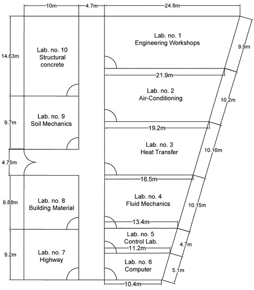
Table 2Cooling loads for 10 different zones based on the simplified worksheet and HAP program
Room number | Room name | Cooling load (Ton) using TETD | Cooling load using HAP program |
1 | Engineering Workshops | 17.58 | 59.9 kW = 17.03 Ton |
2 | Air Conditioning Lab. | 14.25 | 49.65 kW = 14.12 Ton |
3 | Heat Transfer Lab. | 12.28 | 43.78 kW = 12.45Ton |
4 | Fluid Mechanics Lab. | 10.36 | 35.94 kW = 10.22 Ton |
5 | Control Lab. | 5.12 | 17.65 kW = 5.02 Ton |
6 | Computer Lab. | 5.55 | 20.15 kW = 5.73 Ton |
7 | Highway Lab. | 10.22 | 35.13 kW = 9.99 Ton |
8 | Building Materials Lab. | 9.33 | 32.07 kW = 9.12 Ton |
9 | Soil Mechanics Lab. | 8.81 | 31.12 kW = 8.85 Ton |
10 | Structural Concrete Lab. | 12.16 | 43.71 kW = 12.43 Ton |
The developed sheet has significantly helped reduce the total cost of energy consumption due to the over-sized air conditioning system previously used in the building. the thermal loads of the other rooms were estimated following the same steps presented in Table 1 and listed in Table 2. It was observed from Table 2 that as the room’s total area increases, the cooling load also increases. However, the cooling load of Room 6 was slightly higher than that of Room 5, although its area is much smaller. Room 6 is located at the corner, where more of its walls are exposed to sunlight compared to Room 5. a similar observation has been made when comparing Lab 7 and Lab 8.
7. Conclusions
A new worksheet based on the TETD approach was created to estimate the cooling load of a structure under the parameters of the Iraqi weather. at the University of Warith Al-Anbiyaa in Karbala, Iraq, the building is located in the college of engineering. the calculations consider a variety of parameters, including ventilation, lighting, walls, floors, roofs, windows, infiltration, and human factors. When employed in conjunction with an expensive and over-sized air conditioning system, the newly created sheet contributed to significantly reducing energy consumption in the building's previous air conditioning system. It is also possible to use the worksheet to calculate the cooling load of a structure under the conditions that exist in Iraq.
References
-
“International Energy Outlook,” U.S. Energy Information Administration, May 2016.
-
L. Pérez-Lombard, J. Ortiz, and C. Pout, “A review on buildings energy consumption information,” Energy and Buildings, Vol. 40, No. 3, pp. 394–398, Jan. 2008, https://doi.org/10.1016/j.enbuild.2007.03.007
-
Wahid S. Mohammad, Talib K. Murtadha, and Karrar A. Ahmed, “Using TermoDeck System for Pre-Cooling/ Heating to Control the Building Inside Conditions,” Al-Khwarizmi Engineering Journal, Vol. 10, No. 3, p. 13, 2014.
-
Taperit Tongshoob, “A Probabilistic Approach for Cooling Load Calculation,” Thammasat International Journal of Science and Technology, Vol. 9, pp. 29–34, Jan. 2004.
-
Zaheer Ansari, “Cooling Load Estimation for a Multi-story Office Building,” Ph.D. Thesis, National Institute of Technology, Rourkela, Orissa, India, 2014.
-
H. H. Sait, “Estimated thermal load and selecting of suitable air-conditioning systems for a three story educational building,” Procedia Computer Science, Vol. 19, pp. 636–645, 2013, https://doi.org/10.1016/j.procs.2013.06.085
-
U. K. Sen, R. Rana, and A. Punia, “Simplified way to calculate air-conditioning cooling load in Mahendergarh (Haryana),” International Journal of Current Engineering and Technology, Vol. 6, No. 4, pp. 1160–1163, 2016.
-
A. K. Mohammed, R. S. Abdullah, and I. E. Maree, “Comparison between hand calculation and HAP programs for estimating total cooling load for buildings,” ZANCO Journal of Pure and Applied Sciences, Vol. 28, No. 4, pp. 90–96, 2016, https://doi.org/10.21271/zjpas.v28i4.1060
-
O. M. A. Al-Rabghi and K. M. Al-Johani, “Utilizing transfer function method for hourly cooling load calculations,” Energy Conversion and Management, Vol. 38, No. 4, pp. 319–332, Mar. 1997, https://doi.org/10.1016/s0196-8904(96)00051-9
-
F. S. Westphal and R. Lamberts, “The use of simplified weather data to estimate thermal loads of non-residential buildings,” Energy and Buildings, Vol. 36, No. 8, pp. 847–854, Aug. 2004, https://doi.org/10.1016/j.enbuild.2004.01.007
-
“Nonresidential Cooling and Heating Load Calculations,” in ASHRAE Handbook-Fundamentals, Atlanta, 2013.
-
B. Andersson, W. Place, R. Kammerud, and M. P. Scofield, “The impact of building orientation on residential heating and cooling,” Energy and Buildings, Vol. 8, No. 3, pp. 205–224, Aug. 1985, https://doi.org/10.1016/0378-7788(85)90005-2
-
A. Shariah, B. Shalabi, A. Rousan, and B. Tashtoush, “Effects of absorptance of external surfaces on heating and cooling loads of residential buildings in Jordan,” Energy Conversion and Management, Vol. 39, No. 3-4, pp. 273–284, Feb. 1998, https://doi.org/10.1016/s0196-8904(96)00185-9
-
V. Khakre, A. Wankhade, and M. A. Ali, “Cooling load estimation by CLTD method and hap 4.5 for an evaporative cooling system,” International Research Journal of Engineering and Technology, Vol. 4, No. 1, pp. 1457–1460, 2017.
-
D. K. Yadav, A. Srivastava, A. Chauhan, G. Tripathi, and A. Kumar, “Cooling load estimation of a room,” International Research Journal of Engineering and Technology, Vol. 4, No. 4, pp. 719–723, 2017.
-
HAP Quick Reference Guide. 2016.
-
L. Duanmu, Z. Wang, Z. J. Zhai, and X. Li, “A simplified method to predict hourly building cooling load for urban energy planning,” Energy and Buildings, Vol. 58, pp. 281–291, Mar. 2013, https://doi.org/10.1016/j.enbuild.2012.11.029
-
S. K. Gaadhe, S. K. Chavda, and R. D. Bandhiya, “Cooling load estimation of college reading hall,” International Journal of Current Microbiology and Applied Sciences, Vol. 8, No. 3, pp. 2458–2463, Mar. 2019, https://doi.org/10.20546/ijcmas.2019.803.290
-
F. A. Uba, Y. A. K. Fiagbeand, and E. A. Sarsah, “Simplified procedure for estimating air-conditioning cooling load in Ghana,” International Journal of Scientific and Technology Research, Vol. 2, No. 9, pp. 38–46, 2013.
-
S. Zaphar and T. Sheworke, “Computer program for cooling load estimation and comparative analysis with hourly analysis program (HAP) software,” International Journal of Latest Technology in Engineering, Management and Applied Science (IJLTEMAS), Vol. 7, No. 6, pp. 53–61, 2018.
-
O. Kaşka, R. Yumrutaş, and O. Arpa, “Theoretical and experimental investigation of total equivalent temperature difference (TETD) values for building walls and flat roofs in Turkey,” Applied Energy, Vol. 86, No. 5, pp. 737–747, May 2009, https://doi.org/10.1016/j.apenergy.2008.09.010
About this article

