Abstract
In order to realize the accurate judgment of the ground fault and improve the fault discrimination effect, this paper proposes a low-current ground fault discrimination method for the primary and secondary fusion complete sets of equipment under the calculation of three-phase asymmetric harmonic power flow. The three-phase asymmetric harmonic power flow calculation is carried out, the ground fault line selection model is constructed according to the calculation results, and the faulted line is obtained by the zero-sequence active component method and the zero-sequence reactive power component method; the wavelet packet transform method is used to extract the transient zero-sequence power direction, and use it as a line selection criterion to identify whether a ground fault occurs. The amplitude characteristic enhancement value of each section is obtained by calculation. According to the distribution characteristics of the zero-sequence current amplitude of the faulted feeder, the corresponding section is selected as the fault section, and the mutation logic array is used in the determined fault section to realize the low-current grounding fault judgment. The experimental results show that the method has high judgment accuracy in practical application, and the highest value is 98.5 %, which indicates that the method can accurately judge the fault line and determine whether ground fault occurs.
1. Introduction
Most of today’s distribution networks are low-current grounding systems, and the detection of grounding faults has always been a technical problem plaguing the operation of distribution networks [1]. In recent years, with the wide application of power electronics technology and the increase of various nonlinear loads, harmonic pollution in power system has become increasingly serious, which has become a public hazard affecting power quality [2]. With the increase of people’s electricity demand, eliminating the risk of accident expansion and further improving the safety and reliability of power supply have been put on the agenda. However, the identification and judgment of small current ground fault of primary and secondary integrated equipment still need to be improved [3]. At present, people generally use the method of single-phase model analysis to calculate the distribution of harmonics, but the accuracy of this method is difficult to meet the actual demand, so it is necessary to study a method that can meet the effective discrimination of small-current ground faults of primary and secondary fusion equipment [4].
Reference [5] proposed a discrimination algorithm for the direction of grounding fault in flexible grounding system based on the change of zero sequence admittance. By analyzing the zero sequence measurement admittance characteristics of the upstream, downstream and sound lines of the fault point before and after the parallel small resistance is put into operation when a single-phase grounding fault occurs in the flexible grounding system. It is found that the zero-sequence measurement admittance of the downstream of the fault point and the sound line before and after the connection of the small parallel resistance is unchanged, and the modulus-to-value ratio is 1, while the modulus-to-value ratio of the zero-sequence measurement admittance of the upstream line of the fault point is much larger than 1. This method is not easy to be affected by line parameters and transition resistance, but its detection accuracy still needs to be improved. Reference [6] proposed a high resistance grounding fault diagnosis method based on the projection difference between the neutral point current and the line zero sequence current. After the grounding fault occurs, the fault line passes through the grounding point and the system neutral point to form a basic zero sequence circuit. Because the neutral point current is resistive, the difference between the projection of the zero sequence current of the fault line on the neutral point current and the neutral point current is small, while the zero sequence current of the non fault line is basically capacitive, and the difference between the projection of the zero sequence current of the non fault line on the neutral point and the neutral point current is large. This method has high sensitivity and reliability, but it is not accurate enough to identify the fault of the docking ground. Reference [7] proposed a method to identify the grounding phase that can adapt to the asymmetry of the system. If only one phase voltage amplitude decreases after the fault compared with that before the fault, this phase is the fault phase; If two-phase voltage amplitude decreases, the lagging phase of the voltage amplitude increasing phase in the neutral ungrounded system is the fault phase, and the leading phase of the voltage amplitude increasing phase in the over compensated state of the resonant grounding system is the fault phase. This method can accurately identify the phase of ground fault under asymmetric conditions, but it is difficult to be applied to other conditions for accurate detection.
On the basis of the above methods, in order to further improve the effect of fault identification, considering the single phase has been difficult to meet the needs of today’s harmonic power flow calculation, and no convergence problem may emerge in the traditional algorithm, based on the asymmetric three-phase harmonic power flow calculation, for a quadratic convergence complete equipment for small current grounding fault. In this paper, the three-phase asymmetric harmonic power flow is calculated first. According to the calculation results, the grounding fault line selection model is built, and then the fault line is obtained; the transient zero-sequence power direction is extracted by wavelet packet transform method, which is used as the line selection criterion to judge whether ground fault occurs; the amplitude characteristic enhancement value of each section is calculated, and the fault section is selected, in which the mutation logic array is used to determine the small current ground fault.
2. Ground fault line selection
2.1. Three-phase asymmetric harmonic power flow calculation
Under normal circumstances, it is impossible to achieve three-phase symmetry in the power system, so a large error will inevitably occur when the single-phase model analysis method is used to calculate the harmonic power flow. In order to more accurately calculate the distribution of harmonics in the power system, and to solve the problem that traditional power flow algorithms may not converge, this paper proposes a three-phase asymmetric harmonic power flow calculation method.
In the three-phase power flow calculation, the primary and secondary fusion equipment is approximately regarded as a symmetrical element, so it has the characteristics of positive, negative and zero-sequence decoupling, and its positive, negative and zero-sequence impedances are set as , , , for the primary and secondary fusion equipment, generally , therefore, after the transformation of the sequence component and the phase component, it is easy to obtain the phase impedance form of the primary and secondary fusion equipment:
in the formula, , , and represent the self-impedance of , , and , respectively; , , and represent the mutual impedance of , , and , respectively. When there is no zero-sequence path on the side of the primary and secondary fusion equipment, it is only necessary to set to zero.
The above discussion is the three-phase model of the primary and secondary fusion equipment in the case of fundamental waves. In the case of harmonics, the equivalent inductance of the primary and secondary fusion equipment can be approximately considered unchanged, and its harmonic reactance is proportional to the harmonic order. The skin effect of the winding and the eddy current loss of the iron core will increase under the action of harmonics. According to some statistical data, the harmonic equivalent resistance of the primary and secondary fusion equipment is roughly the same as the harmonic order proportional to the square root. Then the -order harmonic impedance of the primary and secondary fusion equipment can be expressed as:
where, represents the harmonic order; and respectively represent the fundamental wave resistance and the corresponding sequence reactance of the primary and secondary fusion equipment. Therefore, referring to the derivation in the case of the fundamental wave, it is not difficult to obtain the three-phase impedance form under the harmonics of the primary and secondary fusion equipment.
2.2. Establishment of ground fault line selection model
Based on the calculation results of three-phase asymmetric harmonic power flow, a ground fault line selection model is constructed.
2.2.1. Zero-sequence active component method
In the power system, due to the asymmetry of the three-phase load of the line, zero-sequence voltage will also appear in the line. At this time, the characteristics of the line are the same as those of the leakage fault, and the active and reactive components will also be generated. If it is considered that there is leakage at this time, it will cause misjudgment. In the power system, it is generally considered that leakage occurs when the generated zero-sequence voltage exceeds 15 % of the circuit phase voltage. Using the active component method and the reactive component method to determine whether there is leakage, there will be a threshold for the system, so there are:
where, represents the phase voltage in the power system; and represent the zero-sequence voltage and zero-sequence current generated by the power system, respectively; represents the operating resistance during leakage; represents the parasitic impedance of each line; and respectively Represents the active and reactive components when the zero-sequence voltage is 15 % of the phase voltage; represents the phase difference between the zero-sequence current and the fundamental zero-sequence voltage.
Assuming that the zero-sequence current when the grid fault occurs is , and the zero-sequence voltage is , there are:
Obviously, there is for the non-faulty branch, and for the faulty branch, and the value of the faulty branch is much larger than the value of for the non-faulty line.
Therefore, according to this method, the membership function of the zero-sequence active component method is determined:
where, represents the zero-sequence active component value of the line.
2.2.2. Zero-sequence reactive component method
The zero-sequence reactive component method uses the characteristic of capacitive impedance in the line to extract the reactive component of the fault current and calculate the power component. When making the criterion, the zero-sequence voltage is rotated 90° clockwise, and the reactive power component is calculated with the zero-sequence current, so there is in the faulty line and in the non-faulty line.
The principle of the zero-sequence reactive component method is the same as that of the zero-sequence active component method. According to statistics and expert experience, the membership function of the zero-sequence reactive component method is:
2.3. Ground fault wavelet packet line selection
The key to ground fault treatment is to select the characteristic quantity of the fault for analysis. In view of the problem that the steady-state fault characteristics are not obvious when the ground fault occurs in the small current grounding system, the wavelet packet transform method [8, 9] can be used to extract the transient zero sequence power direction as the line selection criterion to identify whether the ground fault occurs. The wavelet packet transform method has finer signal analysis ability and can better and accurately judge whether the ground fault occurs.
2.3.1. Theoretical analysis of wavelet packet transform
Multi-resolution analysis (MRA) theory [10], as the basic framework in wavelet analysis, satisfies the two-scale equation:
where, represents the scaling function; represents wavelet function; Both and represent wavelet decomposition filter bank coefficients. When the coefficients of the decomposition filter bank are known, the wavelet decomposition of the original signal can be realized by Mallat fast algorithm. For orthogonal wavelets with good normality conditions, and form a conjugate orthogonal filter bank (CQF), which has the ability to divide higher frequency octaves, can improve the frequency domain resolution and reduce the computational complexity.
For the function family derived from the expansion and displacement of the basic wavelet , if the framework conditions are satisfied, the original signal can be stably reconstructed according to the wavelet transform result. The reconstruction formula is:
where, and represent the wavelet reconstruction filter bank coefficients corresponding to and , respectively.
Through the above-mentioned wavelet reconstruction method [11], the information of the original signal in different frequency bands can be obtained, which provides the basis for the extraction and analysis of the transient characteristic signal during ground fault.
2.3.2. Fault feature extraction
When a ground fault occurs in a small current grounding system, the phase of the transient zero sequence current of the fault branch is opposite to that of the transient zero sequence voltage, the phase of the transient zero sequence current of the non fault branch is the same as that of the transient zero sequence voltage, and the direction of the transient zero sequence power is opposite to that of the fault branch [12, 13]. The wavelet packet is used to decompose the transient characteristics of zero sequence voltage and zero sequence current by orthogonal wavelet, and the information of the original signal in different frequency bands is obtained. The frequency band in the power frequency region is filtered out. The high-frequency energy in the remaining frequency band includes the grounding characteristics of transient zero sequence voltage and zero sequence current, and the grounding fault of this branch is judged according to the direction of transient zero sequence power.
After applying the above transient zero-sequence power method based on wavelet packet transform, the frequency domain resolution can be effectively improved, and fault features can be better extracted. According to the phase relationship between the transient zero-sequence current and the zero-sequence voltage at grounding, the transient zero-sequence Power direction, which in turn can identify whether the line is a ground fault line.
3. Ground fault zone location
In order to enhance the amplitude characteristics and facilitate the detection and collection of fault signals, an adjustable zero-sequence current signal is injected into the low-current grounding system through the PWM active inverter device, and the neutral point voltage is continuously regulated, thereby regulating the fault phase voltage. Fig. 1 is a schematic diagram of the structure of the neutral point injection signal.
In Fig. 1, , and are the power supply voltages of , and phases, , , , , , are the conductance and capacitance of the three phases to ground, and is the zero injected by the PWM active inverter device. sequence current. Taking phase reference, when a ground fault occurs in the distribution network shown in Fig. 1, the relationship between the neutral point voltage and the injection current is:
Fig. 1Schematic diagram of the neutral point injection signal structure
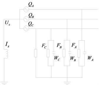
Adjust the neutral point voltage , the fault phase voltage , to achieve fault arc suppression. The value of the injected zero sequence current should be:
Use the FTU or fault indicator to collect the zero-sequence current signal corresponding to each terminal and upload it to the master station, make a difference between the zero-sequence current of each section during arc suppression and extract the amplitude:
where, and represent the adjacent detection points, ; represents the scalar sum of the ground admittance.
After a delay of 5 s, the injected zero-sequence current signal is changed, and the neutral point voltage is regulated, so as to regulate the fault phase power supply voltage whose fault phase voltage is times: , and at this time. Through the active detection of the injected signal, it will not depend on the change of the parameters of the asymmetric distribution network before and after the occurrence of the ground fault, eliminate the influence of the false zero-sequence amplitude component generated by the three-phase unbalance, amplify the fault characteristics, and facilitate the collection of the fault steady-state component. with measurement. Considering that the fault phase voltage and neutral point voltage do not exceed times the phase voltage, the definition domain of the regulation coefficient is taken as [0,1]. According to Eq. (15), the corresponding injection current is the injected current signal at this time:
After the fault arc extinguishing delay of 5 s, the primary duration of regulating the zero-sequence current is 50 ms, and the value is changed to continue regulating after the compensation arc extinguishing is put into operation for 2 s. There is a transient process in the control process, and a short-term inrush current will appear. In the steady state of the fault, the fault characteristics are amplified, the regulation coefficient and regulation range are determined, and the adverse impact on the distribution network is reduced. The standard GB/T 50064-2014 stipulates that the residual current at the fault point of the 6-66 kV distribution network should not exceed 10 A, and the coefficient for regulating the magnitude of the fault phase voltage after the arc extinguishing delay satisfies:
It can be seen from Eq. (16) that when , the range of the control coefficient is , where ; when , the control coefficient can take values in the entire definition domain. The voltage phasor diagram of the regulation process is shown in Fig. 2.
Fig. 2Voltage phasor during regulation process
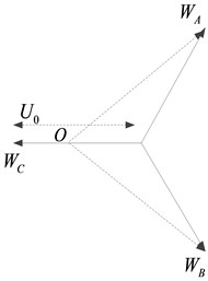
In Fig. 2, in the process of regulating the voltage, the zero-potential point moves along the -phasor direction. The fault characteristics gradually increase, limit the voltage rise of the non-faulty phase, and reduce the breakdown risk of the weak insulation of the non-faulty phase. At the same time, the amplitude of the fault current is limited, and the inrush current is small. For the healthy section, the difference of the zero-sequence current amplitude is only related to the ground parameters of the section; for the fault section, in addition to the ground parameters, it is also related to the transition resistance value, so the zero-sequence current difference amplitude of each section is:
where, and respectively represent the amplitude components corresponding to the and detection points when the control fault phase voltage is times the power supply voltage; represents the control coefficient interval value.
In order to maximize the amplitude feature, the amplitude feature enhancement sequence when the fault feature is amplified to different degrees is constructed for each detection section:
Establish an amplitude accumulation strategy under the magnification feature to evaluate the difference, and superimpose each element in Eq. (20) to obtain the amplitude feature enhancement value of each segment:
where, represents the first regulation coefficient. When the transition resistance is small and satisfies , select the initial control coefficient , and the control coefficient interval value , namely . When the transition resistance is large, the control range is [0, 1] interval, . The amplitude characteristic of the sound section in Eq. (19) shows a decreasing trend. Considering that the maximum amplitude characteristic of the sound section is smaller than the threshold, the Eq. (18) can be substituted, the threshold can be set, and a certain margin can be reserved. According to the engineering site and the accuracy settings of the detection equipment. The amplitude characteristic enhancement value of each section is calculated, and the corresponding section is selected as the fault section according to the distribution characteristics of the zero-sequence current amplitude of the faulted feeder.
4. Method for determining small current grounding fault based on mutation logic array
Since the small current ground fault can cause the current change of the faulted phase upstream of the fault point, the fault point can be determined by analyzing the current change before and after the fault of each feeder.
Definition of feeder real-time current array describes the , and three-phase real-time operating states of all switches and distribution transformers of a distribution feeder, and the specific description is as follows:
where, represents the real-time current value of phase of the -th switch or distribution transformer (distribution transformer) included in the feeder; represents the real-time current value of phase of the -th switch or distribution transformer included in the feeder; represents the real-time current value of phase of the -th switch or distribution transformer included in the feeder; , represent the total number of switches and distribution transformers included in the feeder.
Definition of feeder history current array describes the , and three-phase historical operation states of all switches and distribution transformers of a distribution feeder, and the specific description is as follows:
where, , and are the historical current values of , and phases of the -th switch or distribution transformer included in the feeder, respectively. The historical time can be set according to the terminal type. If it is a high-precision real-time acquisition device with a short equal sampling interval, the historical time can be set to 2-5 min before the current time; if the sampling interval such as a fault indicator and an intelligent distribution transformer terminal is longer if the acquisition device is a collection device, the historical time can be set to 5-10 min before the current time; if the collection device is a mixed configuration of fault indicators, the historical time can be set to 5-10 min before the current time; If it is forwarded by the electrical information collection system, the historical time can be set as 5-10 min before the current time. The purpose of the time setting is to ensure that all data are uploaded to the DMS master station. When a ground fault occurs, the real-time current array of the feeder after the fault and the historical current array of the feeder before the fault can be used to calculate the steady-state current change caused by the fault. The specific description is:
where, represents the sudden change current matrix of the feeder, which is a matrix. For the convenience of calculation, the sudden change of feeder current is expressed by the feeder mutation logic matrix :
Among them:
where, represents the -phase sudden change current logic value of the -th equipment of the feeder; represents the -phase sudden change current logic value of the -th equipment of the feeder; represents the -phase sudden change current logic value of the -th equipment of the feeder; , and represent the , and phase current change values of the -th device in the feeder mutation current array respectively; represents the threshold coefficient, the value range is (0, 1), represents the capacitor current threshold, and its value is the same as line type, line length and number of substation outgoing loops are all relevant.
If the feeder mutation logic array is a zero array, it means that the feeder has no ground fault; if is a non-zero array, it means that the feeder has a ground fault, and the row where the non-zero element is located indicates the phase difference of the ground fault.
If the elements in the -th row of the feeder mutation logic array are non-zero, all non-zero elements are extracted to form the mutation current logic table , which is specifically described as:
where, represents the device number represented by the -th logical 1 element in the -th row of , ; represents the total number of non-zero elements in the -th row of .
Obviously, is an unordered table, and is reordered from parent to child according to the parent-child relationship of the equipment, and the mutation current logical order table is obtained. The specific description is as follows:
where, represents the device number, ; represents the device number of the parent node of the device ; represents the device number of the child node of the device .
From the above analysis, it can be seen that the ground fault occurs in the minimum fault judgment interval where the last element of the abrupt current logical sequence table is the parent node, thus realizing the low-current ground fault judgment of the primary and secondary integrated equipment [14, 15].
5. Experimental studies
In order to verify the validity of the proposed method for judging the low-current grounding fault of the primary and secondary fusion complete sets of equipment under the calculation of three-phase asymmetric harmonic power flow, experiments were carried out.
5.1. Experimental situation
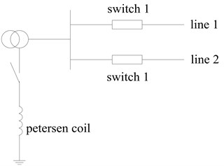
Experiments were carried out on the RTplus real-time digital simulation system to examine the ground fault discrimination function of the primary and secondary fusion equipment. The pilot is located in a 35 kV substation, which has 7 outgoing lines, all of which are located in mountainous areas and are prone to failures. Since August 2015, 25 ground faults have occurred since the installation of primary and secondary fusion equipment with grounding function on the 7 outgoing lines. It is used as an experimental pilot to verify the discriminative effect of the proposed method. The simulated experimental system is shown in Fig. 3. A complete set of primary and secondary fusion equipment is installed on each outlet line, the main transformer is grounded through the arc suppression coil, and the total capacitance current of the system is 15 A.
Fig. 3System diagram of small current ground fault discrimination experiment
5.2. Analysis of experimental results
(1) The ground fault is on line 1.
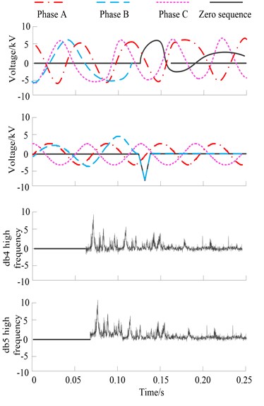
Fig. 4 shows the three-phase voltage and current and zero-sequence voltage and current waveforms on line 1 measured by switch 1. After the fault, the zero sequence current on line 1 is 6.3 A. The bottom part of Fig. 4 is the use of db4 wavelet and db5 wavelet to extract the peak waveform of the high-frequency part of the zero-sequence current.
It can be seen from Fig. 4 that at the moment of the fault, the zero sequence current has a high-frequency component. The high-frequency value of db wavelet is extracted and compared with the average value of high-frequency values in other segments of wavelet in the power frequency cycle to obtain a multiple. The multiple value obtained by db4-8 wavelet is shown in Table 1.
Table 1Multiples table of db4-8 wavelet analysis results when line 1 fails
db wavelet | 4 | 5 | 6 | 7 | 8 |
Multiple | 87 | 73 | 91 | 112 | 100 |
As shown in Table 1, if the fault threshold is set to 30 and multiple thresholds are greater than 30, it can be determined that line 1 where the switch is located is a ground fault line.
(2) The ground fault is on line 2.
Fig. 5 shows the three-phase voltage and current and zero-sequence voltage and current waveforms on line 1 measured by switch 1. After the fault, the zero sequence current on line 1 is 3.2 A.
Fig. 4Waveform diagram of wavelet high-frequency analysis results of line 1 primary and secondary fusion equipment
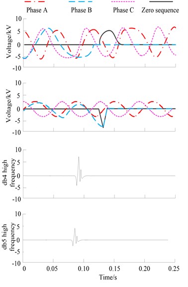
Fig. 5Waveform diagram of wavelet high-frequency analysis results of line 2 primary and secondary fusion equipment
In the lower part of Fig. 5, db4 wavelet and db5 wavelet are also used to extract the peak waveform of the high-frequency part of zero sequence current. See Table 2 for the multiple value obtained by db4-8 wavelet.
Table 2Multiples table of db4-8 wavelet analysis results when line 2 is faulty
db wavelet | 4 | 5 | 6 | 7 | 8 |
Multiple | 7.0 | 7.4 | 8.1 | 8.2 | 7.5 |
As can be seen from Table 2, the threshold for judging faults is set to 30, and all times are not greater than this value. You can determine the line where the switch is located, that is, line 1 is not a grounding fault line. The above experimental simulation results verify the accuracy of the proposed method.
(3) Verification of the accuracy of ground fault discrimination.
In order to further verify the effectiveness of the proposed method, five factors that may affect the ground fault discrimination were mainly considered during the test, as shown in Table 3.
Under different influencing factors, the ground fault occurs on the simulated feeder, and the ground fault discrimination and processing functions of the primary and secondary fusion equipment of the proposed method are evaluated. The experimental results are shown in Table 4.
From the experimental results shown in Table 4, the ground fault discrimination results of the primary and secondary fusion equipment meet the expected requirements, which proves that the proposed method is feasible and can meet the discrimination requirements. The method has high judgment accuracy in practical application, and the highest value of judgment accuracy reaches 98.5 %, and there is no false alarm of ground fault on non-faulty lines, indicating that the method has high stability.
Table 3Factors affecting ground fault discrimination
Serial number | Influencing factors | Remark |
1 | Grounding method | Ungrounded, grounded by arc suppression coil |
2 | Fault transition resistance | 1-1000 Ω |
3 | Fault type | Stability grounding, arc grounding |
4 | Fault location | Beginning, end, middle of the line |
5 | Faulty phase | A, B, C |
Table 4Ground fault test results
Fault type | Fault transition resistance / Ω | Ground fault recognition rate / % |
Stable ground | 0-500 | 98.5 |
1000 | 97.9 | |
Arc ground | 0-500 | 98.0 |
1000 | 97.8 |
6. Conclusions
In order to realize the accurate judgment ground fault, improve the effect of fault identification, considering the single phase has been difficult to meet the needs of today’s harmonic power flow calculation, and no convergence problem may emerge in the traditional algorithm, based on the asymmetric three-phase harmonic power flow calculation, for a quadratic convergence complete equipment for small current grounding fault. The final experimental results show that the method can accurately judge the fault line, the highest judgment accuracy is 98.5 %, and can effectively judge whether the ground fault occurs.
References
-
M. Coppo, F. Bignucolo, R. Turri, H. Griffiths, N. Harid, and A. Haddad, “Analysis of frequency distribution of ground fault-current magnitude in transmission networks for electrical safety evaluation,” Electric Power Systems Research, Vol. 173, No. 8, pp. 100–111, 2019.
-
Dhaval N. Tailor and V. Makwana, “Analysis of faulted power system during simultaneous open conductor and ground fault,” IET Generation Transmission and Distribution, Vol. 14, No. 22, pp. 5319–5326, 2020.
-
N. Cho, S. Yun, and J. Jung, “Determining the reverse fault current by the type of transformer and Distributed Generation in distribution system during the single-line to ground fault,” Renewable and Sustainable Energy Reviews, Vol. 109, pp. 102–115, Jul. 2019, https://doi.org/10.1016/j.rser.2019.04.036
-
X. Yue, X. H. Zhang, J. H. Wang, and Y. Yu, “Line selection of resonance grounding fault based on VMD and grey comprehensive correlation degree,” Computer Simulation, Vol. 39, No. 4, pp. 76–79, 2022.
-
F. Yang, X. Jin, Y. Shen, Y. Lei, Y. D. Xue, and B. Y. Xu, “Dicrimination algorithm of grounding fault direction based on variation of zero-sequence admittance in flexible grounding system,” Automation of Electric Power Systems, Vol. 44, No. 17, pp. 88–94, 2020.
-
Y. R. Sheng, W. Cong, X. H. Bu, and X. M. Li, “Detection method of high impedance grounding fault based on differential current of zero-sequence current projection and neutral point current in low-resistance grounding system,” Electric Power Automation Equipment, Vol. 39, No. 3, pp. 17–22, 2019.
-
L. L. Zhang, Y. Zhang, Y. D. Xue, C. Wang, and Z. M. Shao, “Fault phase identification of non-solidly grounding system considering system asymmetry,” Electric Power Automation Equipment, Vol. 39, No. 4, pp. 24–29, 2019.
-
D. A. Gadanayak and R. K. Mallick, “Interharmonics based high impedance fault detection in distribution systems using maximum overlap wavelet packet transform and a modified empirical mode decomposition,” International Journal of Electrical Power and Energy Systems, Vol. 112, pp. 282–293, Nov. 2019, https://doi.org/10.1016/j.ijepes.2019.04.050
-
J. B. Salyers, Y. Dong, and Y. Gai, “Continuous wavelet transform for decoding finger movements from single-channel EEG,” IEEE Transactions on Biomedical Engineering, Vol. 66, No. 6, pp. 1588–1597, Jun. 2019, https://doi.org/10.1109/tbme.2018.2876068
-
O. Habimana, “Wavelet multiresolution analysis of the liquidity effect and monetary neutrality,” Computational Economics, Vol. 53, No. 1, pp. 85–110, Jan. 2019, https://doi.org/10.1007/s10614-017-9725-1
-
N. Holighaus, Günther Koliander, Zdeněk Průša, and L. D. Abreu, “Characterization of analytic wavelet transforms and a new phaseless reconstruction algorithm,” IEEE Transactions on Signal Processing, Vol. 67, No. 15, pp. 3894–3908, 2019.
-
J. D. Liu, L. Q. Dong, C. Xue, Y. D. Xue, J. Li, and Y. Chen, “Fault location of a small current grounding fault based on distribution characteristics of zero sequence voltage,” Power System Protection and Control, Vol. 50, No. 3, pp. 59–67, 2022.
-
J. Qiu, X. Cui, Y. Tian, B. Wang, and G. H. Li, “Analysis of the arc high impedance grounding faults voltage characteristics in non-effective grounding feeders,” Power System Protection and Control, Vol. 47, No. 16, pp. 115–121, 2019.
-
H. L. Zhao, Q. Z. Chen, Y. F. Liang, and S. L. Pang, “A fault location method of single phase earth fault in small current neutral grounding system,” Power System Protection and Control, Vol. 47, No. 19, pp. 85–93, 2019.
-
S. Z. Hou, W. Guo, L. M. Cao, Z. W. Ding, and Y. Z. Tian, “Simulation study on single-phase grounding fault of small current system for EMD and ANF,” Modern Electronics Technique, Vol. 43, No. 19, pp. 134–137, 2020.
Cited by
About this article

The study was supported by Science and technology project support by STATE GRID LIAONING ELECTRIC POWER SUPPLY CO., LTD., Research and application of phase asymmetric ground fault detection technology, 2021YF-40.
The datasets generated during and/or analyzed during the current study are available from the corresponding author on reasonable request.
The authors declare that they have no conflict of interest.
