Abstract
In view of the safety problems caused by the pitch stability of the offshore waste collection platform, the three-dimensional model of the collection platform hull was established by SolidWorks software, and the influence of the installation parameters of NACA fin stabilizers on the pitch stability of the collection platform hull was discussed based on three-dimensional potential flow theory. The results show that the installation parameters of NACA fin stabilizers have an essential influence on the pitch stability of the collection platform hull. The larger the positive installation angle and the farther away the bow fin is from the midship, the smaller the peak values of pitch motion response. While the tail fin is not suitable to be installed near 600 mm of midship to avoid severe longitudinal movement of the hull.
1. Introduction
The safety of ships has been paid attention to worldwide, and many scholars have studied and improved the stability of ships. Zhou et al. [1] studied the influence of random longitudinal and oblique waves on the rolling performance of C11 container ship. Huang et al. [2] studied the motion response of S175 hull in bidirectional and unidirectional regular waves and analyzed its seakeeping. Based on the effective model of ship hydrostatic motion and using the finite volume method, Maki et al. [3] discussed the correlation between the stability loss of periodic oscillation and the dumping of ships. Pérez-Arribas and Calderon-Sanchez [4] established a B-spline model of a SWATH ship hull based on a parametric computer-based technique, and researched the importance of the center of buoyancy and center of flotation in the seakeeping performance of the SWATH as well as the influence of the waterplane on the ship stability characteristics. Ali et al. [5] investigated the semi-SWATH ship with fin stabilizers in deep water and shallow water, and the results indicated that the changes in the installation angle of the fin stabilizers had a certain influence on the resistance, waveform, and pitch of the ship. Kusdiana et al. [6] investigated the influence of different attack angles of NACA0013 fin stabilizer on ship resistance.
The offshore waste collection platform (Fig. 1(a)) is a new cleaning device used to collect offshore waste, reduce marine pollution and improve the marine environment. Due to the small submersible area of the collection platform, the pitch angle of the hull changes significantly with the fluctuation of the waves, which in turn leads to a sharp change in the hydrodynamic tilt torque, which causes the collection platform to generate pitch and lose normal navigation ability, so it is very important to ensure the longitudinal stability of the collection platform. To improve the pitch stability of the collection platform in the sea and reduce the occurrence of marine accidents such as ship tilting caused by insufficient stability, the influence of the installation parameters of NACA fin stabilizers on the pitch stability of the collection platform hull was discussed based on the three-dimensional potential flow theory.
2. Research model
Fig. 1(a) shows the three-dimensional model of the offshore waste collection platform. From Fig. 1(a), it can be seen that the collection platform has the main structure of a crawler small waterplane catamaran with the collection system, compression system, and hull, which can realize unmanned operation. The collection system is equipped with a conveyor belt-type negative pressure absorbing device, and a horn-type collection port. The hull consists of prop (Fig. 1(b)), a floating platform, and a submerged body. The submerged body is similar to that of a submarine, and the long and narrow pillars support the floating platform. The main geometric and performance parameters of the collection platform include hull length of 2500 mm, hull width of 1500 mm, submerged body width of 200 mm, full load draft depth of 200 mm, and maximum speed of 5 kn.
Fig. 1Offshore waste collection platform
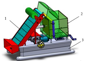
a) Three-dimensional model of offshore waste collection platform: 1 – collection system; 2 – compression system; 3 – hull
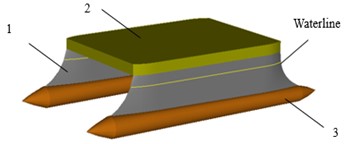
b) Hull: 1 – prop; 2 – floating platform; 3 –submerged body
3. Mathematical model
According to three-dimensional potential flow theory, the velocity potential around the platform can be expressed as:
where denotes the constant speed of the collection platform; represents the steady perturbation due to forward motion; is the first-order velocity potential of the unsteady wave system which varies with the encounter frequency and can be expressed as:
where represents the incident potential; represents the diffraction potential; represents the radiation potential; represents the 6-DOF motion amplitude.
The velocity-potential function should satisfy the Laplace equation:
The boundary conditions are as follows:
(1) The zero-flux condition for fluid across the sea-bottom boundary was calculated as:
(2) After ignoring the disturbed steady flow, the linear-free surface equation is satisfied, such that:
(3) The Neumann condition was obtained based on a zero-flux condition for fluid across the boundary:
(4) When the distance tends to infinity, the hull disturbance disappears:
4. Simulation and analysis
To discuss the influence of NACA fin stabilizers with on the pitch stability of the collection platform hull by ANSYS-AQWA software module, the three-dimensional models of the collection platform hull was established by SolidWorks software. The grid division of the hull are shown in Fig. 2 and the parameters of NACA fin stabilizers are listed in Table 1.
Fig. 2Grid division of the hull with NACA fin stabilizer
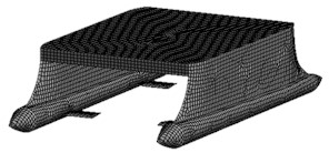
Table 1NACA fin stabilizer parameters
Parameter | Bow fin | Tail fin |
Relative camber | 0 | 0 |
Location of the maximum camber | 0 | 0 |
Relative thickness | 12 % | 12 % |
Elongation (mm) | 100 | 100 |
Chord length (mm) | 200 | 200 |
Aspect ratio | 0.5 | 0.5 |
4.1. Influence of installation angle of NACA fin stabilizer
Usually, the installation angle of the fin stabilizer is defined as the angle between it and the horizontal plane. Here the installation angle of the fin stabilizer –10°, –5°, 5°, and 10°, and the bow and tail fins are installed at the longitudinal positions 600 mm from the midship, respectively.
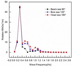
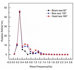
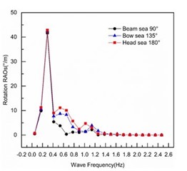
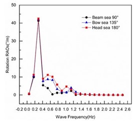
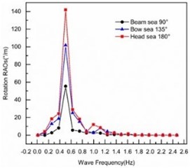
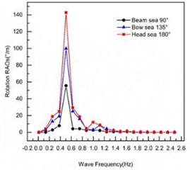
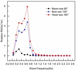
Fig. 3 shows the pitch motion response amplitude curves of the hull with different installation angles of NACA fin stabilizer under the conditions of beam sea 90°, bow sea 135°, and head sea 180°, respectively.
It can be seen from Figs. 3(a), (b), (c), and (d) that with the increase of wave frequency, the hull pitch motion response amplitudes first increase dramatically at different wave direction angles and their peak values reach the maximum when the wave frequency is 0.29 Hz, implying that the hull pitch motion is the most obvious and the pitch stability is the worst at this wave frequency. After 0.29 Hz, the hull pitch response amplitudes decrease rapidly and produce two small wave peaks. The hull is a catamaran with two symmetrical plates, so the above motion response peak values are caused by its radiative motion at low frequencies. According to Fig. 3(e), the hull with NACA fin stabilizers has the smallest pitch motion response amplitude peak value under the installation angle 10°, followed by that under 5°, and has the largest peak value under –5°.
In a word, the installation angle of the fin stabilizers has a significant influence on the pitch stability of the hull, and the hull has small pitch motion response amplitudes and good pitch stability when 10°.
Fig. 3Pitch motion response amplitude curves of the hull at different installation angles of fin stabilizers
a)–10°
b) –5°
c)5°
d)10°
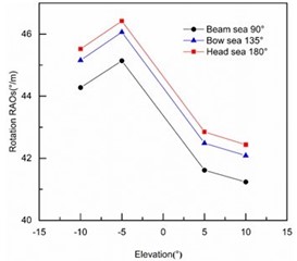
e) Peak curves of the hull pitch motion response amplitude
4.2. Influence of installation position of bow fins
In order to analyze the influence of the installation position of the bow fin on the pitch stability of the hull, the tail fins are installed at the longitudinal position from the midship 600 mm; the installation angle 0°; the distance between the bow fin and midship 300, 450, 600, and 750 mm, respectively.
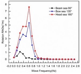
Fig. 4 describes the pitch motion response amplitude curves of the hull with different installation positions of the bow fins under the conditions of beam sea 90°, bow sea 135°, and head sea 180°, respectively.
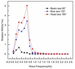
It can be seen from Figs. 4(a), (b), (c), and (d) that when the wave frequency is within 1.61 Hz, the pitch motion response amplitude of the hull fluctuates greatly under different wave angles, and then decays to 0. Further, when the distance from the bow fin stabilizer to the midship 300 mm, 450 mm, the pitch motion response amplitude of the hull reaches the maximum at about 0.5 Hz; under the conditions of 600 mm, 750 mm, it gets the peak value at 0.26 Hz and 0.13 Hz respectively when the hull suffers beam sea 90° and gains the peak value at 0.62 Hz when the hull suffers bow sea 135° and head sea 180°. The reason for the above phenomenon can be attributed to the resonance between the hull and the waves as well as the fluid interference between the two symmetrical plates of the hull. According to Fig. 4(e), the peak value of the hull pitch motion response is large when 600 mm, while it decreases rapidly and greatly when 600 mm.
According to Fig. 4, when 600 mm, the hull has larger peak values of pitch motion response at each wave direction angle which means it has a more violent longitudinal motion. In order to improve the pitch stability of the collection platform hull, it is best to install the bow fin at the longitudinal position far away from the midship.
Fig. 4Pitch motion response amplitude curves of the hull at different installation positions of bow fins
a)300
b) 450
c) 600
d) 750
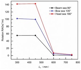
e) Peak curves of the hull pitch motion response amplitude
4.3. Influence of installation position of tail fins
In order to analyze the influence of the installation position of tail fins on the pitch stability of the hull, the bow fins are installed at the longitudinal position from the midship 600 mm; the installation angle 0°; the distance between the tail fin and the midship 300, 450, 600, and 750 mm, respectively.
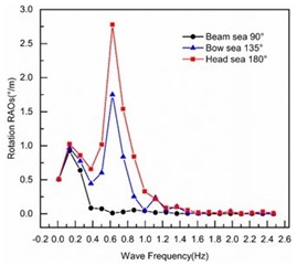
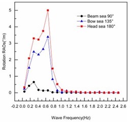
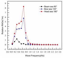
Fig. 5 describes the pitch motion response amplitude curves of the hull with different installation positions of the bow fins under the conditions of beam sea 90°, bow sea 135°, and head sea 180°, respectively.
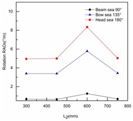
It can be observed from Figs. 5(a), (b), (c), and (d) that when the wave frequency is within 1.5 Hz, the pitch motion response amplitude of the collection platform hull fluctuates greatly under different tail fin installation positions, especially where the tail fin is far from the midship. Under the same installation position of the tail fin in the hull, the larger the wave direction angle is, the larger the pitch motion response amplitude of the hull is. When the frequency is greater than 1.5 Hz, the pitch motion response amplitude of the hull is close to 0 and no longer fluctuates. Fig. 5(e) shows that when the tail fin is installed at the place 600 mm from the midship, the hull has the largest pitch motion response peak and most intense pitch motion under any wave direction angle, while it has a small pitch motion response peak value when 300, 450, 750 mm. Therefore, the tail fin should not be installed about 600 mm from the ship.
Overall, in order to make the tail fin play a role in regulating the longitudinal movement and obtaining better pitch stability of the collection platform, the tail fin should better not be installed in the place about 600 mm away from the midship.
Fig. 5Pitch motion response amplitude curves of the hull at different installation positions of tail fins
a)300
b) 450
c) 600
d) 750
e) Peak curves of the hull pitch motion response amplitude
5. Conclusions
In this paper, the influence of the installation parameters of NACA fin stabilizers on the pitch stability of the collection platform hull was simulated by ANSYS-AQWA software module. The simulation results indicate that the installation parameters of NACA fin stabilizers have an important influence on the pitch stability of the collection platform hull. The hull has less pitch motion response amplitudes and better pitch stability when 10° than those when –10°, –5°, 5°. The hull has larger peak values of pitch motion response and a more violent longitudinal motion when 600 mm. When the tail fin is installed at the place 600 mm from the midship, the hull has larger pitch motion response peak and more intense pitch motion, while it has a small pitch motion response peak value when 300, 450, 750 mm. Therefore, to obtain better stability of the collection platform, it is better to set a larger positive installation angle, and the bow fin should be far away from the midship, while the tail fin should not be installed 600 mm away from the midship.
References
-
X. Zhou, H. Li, and Y. Huang, “Stochastic averaging for estimating a ship roll in random longitudinal or oblique waves,” Marine Structures, Vol. 75, p. 102814, Jan. 2021, https://doi.org/10.1016/j.marstruc.2020.102814
-
S. Huang, J. Jiao, and C. Chen, “CFD prediction of ship seakeeping behavior in bi-directional cross wave compared with in uni-directional regular wave,” Applied Ocean Research, Vol. 107, p. 102426, Feb. 2021, https://doi.org/10.1016/j.apor.2020.102426
-
A. Maki et al., “On the loss of stability of periodic oscillations and its relevance to ship capsize,” Journal of Marine Science and Technology, Vol. 24, No. 3, pp. 846–854, Sep. 2019, https://doi.org/10.1007/s00773-018-0591-x
-
F. Pérez-Arribas and J. Calderon-Sanchez, “A parametric methodology for the preliminary design of SWATH hulls,” Ocean Engineering, Vol. 197, p. 106823, Feb. 2020, https://doi.org/10.1016/j.oceaneng.2019.106823
-
A. Ali, A. Maimun, and Y. M. Ahmed, “Analysis of resistance and generated wave around semi SWATH hull at deep and shallow water,” Journal of Advanced Research in Fluid Mechanics and Thermal Sciences, Vol. 58, No. 2, pp. 247–260, 2019.
-
W. Kusdiana, Semin, I. Made Ariana, C. Kusuma, and B. Ali, “Location analysis of patrol boat fin stabilizer based on numerical method,” in IOP Conference Series: Earth and Environmental Science, Vol. 972, No. 1, p. 012002, Jan. 2022, https://doi.org/10.1088/1755-1315/972/1/012002
About this article

The authors have not disclosed any funding.
The datasets generated during and/or analyzed during the current study are available from the corresponding author on reasonable request.
The authors declare that they have no conflict of interest.
