Abstract
To evaluate the effect of circular holes on the mechanical properties of laminated composite plates with different sizes, static tensile destructive tests were carried out on four different types of composite laminated plates with different layups and aperture sizes. The experimental results showed that for the four types of layup, the strength of the specimens with a diameter of 6.35 mm decreased by 44.3 %, 51.3 %, 48.0 %, and 39.4 % compared to intact specimens, and the greater the proportion of 0° layup, the greater the strength decrease of the perforated specimens. Under the same layup, as the diameter of the circular hole increased, the tensile strength decreased rapidly with the constant ratio of diameter to width. Based on the experimental results, three commonly used models for predicting the residual strength of perforated laminated composite plates, including point stress criterion, average stress criterion, and stress field intensity method, were evaluated. The results showed that the average stress criterion had higher accuracy compared to the point stress criterion and the stress field intensity method.
1. Introduction
In the application of composite materials in structural engineering, various forms of holes inevitably appear at the process separation surfaces and inspection cover. At the same time, notch damage will also occur due to the external environment. The existence of holes breaks the continuity of the long fibers, changes the force transmission path of the structure, and can also cause stress concentration in the area around the hole due to the sudden change of the structure stiffness. Therefore, the existence of holes severely affects the mechanical properties of the structure and affects the service performance of composite materials [1].
The core issue in the study of residual strength of the composite plate with a notch is the selection and use of fracture criteria [2]. Among the fracture criteria proposed, the point stress criterion (PSC) and average stress criterion (ASC) put forward by Whitney and Nuismer are widely accepted and used [3], as well as other modified criteria derived from these criteria [4-5]. These criteria are based on the description of the elastic stress field at the root of the notch in an equivalent orthotropic plate and are expressed using characteristic distances, collectively referred to as the characteristic distance method.
The average stress criterion states that the laminated composite plate fails when the average stress within a characteristic distance from the edge of the hole or crack tip reaches the ultimate strength of an unnotched laminate, while the point stress criterion states that the plate fails when the stress level at a characteristic distance from the edge of the hole or crack tip reaches the ultimate strength of an unnotched laminate. To determine the “material properties” and required in these criteria, physical experiments are needed, and these “material properties” not only depend on the material but also on the stacking sequence, notch shape, and specimen size.
Yao proposed a stress field intensity (SFI) analysis method that considers the influence of the stress gradient at the root of the notch [6-7]. Tang developed a damage influence failure criterion (DI) based on a large amount of experimental data and parameter analysis and fitting methods [8]. This criterion no longer requires “material properties” determined by experiments other than the unidirectional plate performance data of the material system. Chen developed a fiber damage failure criterion (FD) for the damage zone, and believed that the notch strength of fiber-reinforced composite materials could be evaluated by predicting the fracture of the 0° layer fibers, and proposed a fiber fracture criterion for the damage zone [9]. Wu proposed an engineering simplified model for predicting the residual strength of laminated composite plates with circular holes based on the stress field intensity method [10].
In terms of numerical analysis methods, Chang proposed a two-dimensional progressive damage analysis finite element model for the first time, considering the effects of shear nonlinearity, transverse tensile strength, and shear in-place strength, and analyzes the stress concentration at the hole edge of laminated composite plates with holes, and predicts the tensile and compressive strength [11-12]. Li developed the LaRC05 criterion for failure to apply to plane stress problems and proposed a corresponding continuous damage evolution method, which effectively predicts the tensile strength of perforated laminated composite plates [13-14].
Most of the above research focuses on the effects of stacking sequence and opening shape, while less attention has been paid to the proportional magnification of hole diameter and width in specimens, as well as the comparison between various failure criteria. To address these issues, tensile performance of composite laminates with holes was investigated by conducting experiments on four different laminate configurations with varying hole diameters and widths. The effects of hole diameter, stacking ratio, and diameter-width ratio on the tensile performance of laminates were analyzed. Three failure criteria, named point stress criterion (PSC), average stress criterion (ASC), and stress field intensity criterion (SFI), were evaluated based on the experimental results, and their characteristic distances are calculated. By analyzing the characteristic distances, a comparison was made between the three criteria in predicting the residual tensile strength of composite laminates with circular holes.
2. Estimation model for residual strength of composite laminates
2.1. Point stress criterion (PSC)
For an infinitely anisotropic plate with a circular hole of radius subjected to uniform stress in the direction at infinity, this criterion assumes that the laminate fails when the stress at a characteristic distance from the hole edge reaches the ultimate strength of the unnotched laminated plate:
where is the distribution of the -direction stress on the smallest cross-section of the hole; is the characteristic distance, which is determined experimentally.
The laminate is assumed to be equivalent to a homogeneous orthotropic plate. For an orthotropic infinite plate with a circular hole subjected to uniaxial tension, the elastic stress distribution along the axis perpendicular to the loading direction at the edge of the hole can be derived from the Lekhnitskii formula [15], i.e.:
The stress concentration factor at the edge of the hole in the infinitely wide laminated plate is calculated by the formula [16], i.e.:
where, is the in-plane stiffness coefficient of the laminate. For an orthogonal anisotropic infinite plate with a circular hole under uniaxial tension, the failure strength can be obtained by substituting the stress distribution around the hole into Eq. (1):
The critical failure strength of an infinitely wide plate is , is the failure strength of a finite width plate corrected by a finite width correction factor. When the ratio of defect length to the plate width is not greater than 1/3, for a laminated plate with a central circular hole of radius , we have:
where, is the width of the plate.
2.2. Average stress criterion (PSC)
This criterion assumes that the laminated plate fails when the average stress within a certain characteristic distance from the hole edge reaches the ultimate strength of a notch-free laminated plate, i.e.:
where, – characteristic distance determined by experiments. Substitute Eq. (2) into Eq. (6) to obtain the formula for calculating the strength of destruction. For an orthotropic infinitely plate with a central circular hole under uniaxial tension, the formula for calculating the strength can be obtained by substituting Eq. (2) into Eq. (6), i.e.:
where, .
2.3. Stress field intensity (SFI)
The stress field intensity method assumes that the failure of a component with stress concentration depends not only on the peak stress but also on the stress-strain field caused by the stress concentration zone. This method takes into account the influence of stress gradients in the damage zone at the root of the notch, and considers the combined contribution of stress at different material points to the failure of the notch root by allocating weight functions to the stress vectors of all material points in the field strength area. The formula for calculating the failure strength of laminated plates with circular holes based on this method is given by:
where – characteristic distance determined by experiments; .
3. Test
3.1. Test specimens
The test specimens are smooth composite laminates made of medium modulus carbon fiber reinforced M21C epoxy resin unidirectional tapes with a nominal thickness of 0.187 mm per layer. The material properties of the specimens are shown in Table 1.
Table 1Elastic properties of unidirectional M21C/IMA
/ GPa | / GPa | / GPa | |
179 | 8.11 | 0.317 | 4.14 |
The specimens were manufactured using automatic fiber placement and autoclave curing auxiliary process. Two configurations were used: without notch and with a centrally circular hole, as shown in Fig. 1.
The specimens contain 4 typical ply configurations, as shown in Table 2.
According to the different configurations and layups, the test specimens were divided into 28 groups with a total of 144 specimens, as shown in Table 3.
Fig. 1Specimen with hole
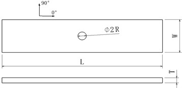
Table 2Ply configurations of test specimens
Lay code | Ply ratio (0/±45/90) | Ply order | Number of layers | Total thickness (mm) |
A | 25/50/25 | [45/0/-45/90]2S | 16 | 2.99 |
B | 50/40/10 | [45/0/-45/0/90/0/45/0/-45/0]s | 20 | 3.74 |
C | 40/40/20 | [45/0/-45/90/0]2S | 20 | 3.74 |
D | 10/80/10 | [45/-45/90/45/-45/45/-45/0/45/-45]s | 20 | 3.74 |
Table 3Test specimen configurations, quantity, and dimensions
Lay code | Notch type | Diameter / mm | Width / mm | Length / mm | Quantity |
A/B/C/D | Without notch | N/A | 31.75 | 247 | 6 |
Circular hole | 6.35 | 31.75 | 247 | 6 | |
Circular hole | 6.35 | 25.4 | 247 | 3 | |
Circular hole | 6.35 | 38.1 | 247 | 3 | |
Circular hole | 12.7 | 63.5 | 374 | 6 | |
Circular hole | 25.4 | 127 | 628 | 6 | |
Circular hole | 50.8 | 254 | 1136 | 6 |
3.2. Test results
The far-field failure strain of the intact specimen reached around 16000 με, while the far-field failure strain of the specimen with a hole decreased to between 5000-8000 με. The experimental failure loads are shown in Table 4, where is the ratio of the hole diameter to the plate width, is the average breaking load, is average value of failure stress, CV is the coefficient of variation of failure load.
Table 4Summary of test fracture information
Lay code | Notch type | Plate width / mm | Hole diameter / mm | (kN) | (MPa) | CV | |
A | Without notch | 31.75 | / | / | 90.2 | 948.7 | 5.38 % |
A | Hole | 31.75 | 6.35 | 0.2 | 50.2 | 528.3 | 1.94 % |
A | Hole | 63.5 | 12.7 | 0.2 | 89 | 468.8 | 3.02 % |
A | Hole | 127 | 25.4 | 0.2 | 160.8 | 423.2 | 0.94 % |
A | Hole | 254 | 50.8 | 0.2 | 276.1 | 363.7 | 1.53 % |
A | Hole | 25.4 | 6.35 | 0.25 | 36.8 | 485 | 2.6 % |
A | Hole | 38.1 | 6.35 | 0.17 | 61.3 | 538.3 | 0.83 % |
B | Without notch | 31.75 | / | / | 200.4 | 1687.8 | 1.53 % |
B | Hole | 31.75 | 6.35 | 0.2 | 97.7 | 822.8 | 2.67 % |
B | Hole | 63.5 | 12.7 | 0.2 | 172.3 | 725.7 | 2.13 % |
B | Hole | 127 | 25.4 | 0.2 | 301 | 633.7 | 2.64 % |
B | Hole | 254 | 50.8 | 0.2 | 501 | 527.3 | 2.43 % |
B | Hole | 25.4 | 6.35 | 0.25 | 74.7 | 786.3 | 2.51 % |
B | Hole | 38.1 | 6.35 | 0.17 | 120.6 | 846.7 | 1.46 % |
C | Without notch | 31.75 | / | / | 158.5 | 1334.5 | 3.7 % |
C | Hole | 31.75 | 6.35 | 0.2 | 82.5 | 694.5 | 1.84 % |
C | Hole | 63.5 | 12.7 | 0.2 | 147.3 | 620 | 1.86 % |
C | Hole | 127 | 25.4 | 0.2 | 260.5 | 548.5 | 1.88 % |
C | Hole | 254 | 50.8 | 0.2 | 441.7 | 465.2 | 2.4 % |
C | Hole | 25.4 | 6.35 | 0.25 | 62.8 | 660.3 | 1.22 % |
C | Hole | 38.1 | 6.35 | 0.17 | 101.5 | 712 | 0.63 % |
D | Without notch | 31.75 | / | / | 65.4 | 550.7 | 1.16 % |
D | Hole | 31.75 | 6.35 | 0.2 | 39.6 | 333.5 | 0.56 % |
D | Hole | 63.5 | 12.7 | 0.2 | 77.4 | 326 | 1.09 % |
D | Hole | 127 | 25.4 | 0.2 | 147.5 | 310.5 | 0.93 % |
D | Hole | 254 | 50.8 | 0.2 | 267.1 | 281.0 | 3.91 % |
D | Hole | 25.4 | 6.35 | 0.25 | 29.3 | 308.7 | 1.34 % |
D | Hole | 38.1 | 6.35 | 0.17 | 49.9 | 350 | 0.48 % |
The experimental results showed low dispersion, with a maximum coefficient of variation of 5.38 %, indicating the reliability of the results. For the four types of layups, the strength of specimens with holes of diameter 6.35 mm was reduced by 44.3 %, 51.3 %, 48.0 %, and 39.4 %, respectively, compared to the intact specimens. It can be seen that the greater the proportion of 0° plies, the greater the reduction in strength of specimens with holes. With the constant ratio of hole diameter to plate width, the tensile strength decreased with the increasing hole diameter.
3.3. Evaluation of failure criteria
Based on the obtained experimental data, the estimation models of PSC, ASC, and SFI were validated. The three failure criteria all require obtaining the corresponding characteristic distances through experiments. Taking the average value of the characteristic distances for different hole diameters, the relative average error (RAE) can be defined as the maximum relative error between the obtained characteristic distance values and the average value of the characteristic distance for the same type of specimen. RAE can be used to evaluate the effectiveness of the estimation models.
The characteristic distances obtained by calculation are shown in Table 5. It can be seen that the characteristic distances obtained for different hole diameters and diameter-width ratios are different. Generally, when the diameter-width ratio is constant and the diameter is less than 25.4 mm, the larger the hole diameter, the larger the characteristic distance. When the hole diameter is constant, the difference in characteristic distances is relatively small, but still shows a slightly decreasing trend with increasing diameter-width ratio.
Table 5Summary of characteristic distances
Lay code | Plate width / mm | Hole diameter / mm | Characteristic distances/mm | |||
(PSC) | (ASC) | (SFI) | ||||
A | 31.75 | 6.35 | 0.2 | 1.13 | 2.99 | 2.24 |
A | 63.5 | 12.7 | 0.2 | 1.59 | 3.88 | 3.13 |
A | 127 | 25.4 | 0.2 | 2.25 | 5.18 | 4.35 |
A | 254 | 50.8 | 0.2 | 2.24 | 4.80 | 4.20 |
A | 25.4 | 6.35 | 0.25 | 0.96 | 2.43 | 1.77 |
A | 38.1 | 6.35 | 0.17 | 1.14 | 3.04 | 2.38 |
B | 31.75 | 6.35 | 0.2 | 0.72 | 1.96 | 1.63 |
B | 63.5 | 12.7 | 0.2 | 1.03 | 2.58 | 2.25 |
B | 127 | 25.4 | 0.2 | 1.36 | 3.16 | 2.86 |
B | 254 | 50.8 | 0.2 | 1.23 | 2.63 | 2.45 |
B | 25.4 | 6.35 | 0.25 | 0.69 | 1.85 | 1.47 |
B | 38.1 | 6.35 | 0.17 | 0.75 | 2.05 | 1.75 |
C | 31.75 | 6.35 | 0.2 | 0.87 | 2.40 | 1.92 |
C | 63.5 | 12.7 | 0.2 | 1.28 | 3.26 | 2.75 |
C | 127 | 25.4 | 0.2 | 1.75 | 4.18 | 3.67 |
C | 254 | 50.8 | 0.2 | 1.83 | 4.02 | 3.67 |
C | 25.4 | 6.35 | 0.25 | 0.82 | 2.23 | 1.70 |
C | 38.1 | 6.35 | 0.17 | 0.90 | 2.49 | 2.05 |
D | 31.75 | 6.35 | 0.2 | 1.57 | 4.03 | 2.75 |
D | 63.5 | 12.7 | 0.2 | 2.95 | 7.39 | 5.16 |
D | 127 | 25.4 | 0.2 | 5.17 | 12.30 | 8.94 |
D | 254 | 50.8 | 0.2 | 7.68 | 16.64 | 12.80 |
D | 25.4 | 6.35 | 0.25 | 1.37 | 3.34 | 2.19 |
D | 38.1 | 6.35 | 0.17 | 1.72 | 4.58 | 3.22 |
The average characteristic distance and relative error are shown in Table 6, where is the average characteristic distance of PSC, is the average characteristic distance of ASC, is the average characteristic distance of SFI, RAE is the relative average error. It can be seen that the prediction accuracy of the average stress criterion is better than that of the point stress criterion and the stress field intensity method.
Table 6Summary of relative error
Lay code | PSC | ASC | SFI | |||
/ mm | RAE | / mm | RAE | / mm | RAE | |
A | 1.55 | 45.0 % | 3.72 | 39.3 % | 3.01 | 44.4 % |
B | 0.96 | 41.2 % | 2.37 | 33.2 % | 2.07 | 38.3 % |
C | 1.24 | 47.4 % | 3.10 | 35.0 % | 2.63 | 39.7 % |
D | 3.41 | 125.2 % | 8.05 | 106.8 % | 5.84 | 119.1 % |
In fact, by substituting the average value of the characteristic distance into the corresponding residual strength calculation formula, the errors of the three criteria relative to the test results can be obtained. The maximum errors for each type of laminate were listed in Table 7. It can be seen that in any case, the average stress criterion is the better criterion, while for the A and D layers, the accuracy obtained by the stress field strength criterion has made it inapplicable. For the D layer, which is dominated by the 45-degree layer, all three criteria showed relatively large errors.
Table 7Maximum error for each type of laminate
Lay code | Error (PSC) / % | Error (ASC) / % | Error (SFI) / % |
A | 18.7 | 12.5 | 22.8 |
B | 13.7 | 7.8 | 13.8 |
C | 16.4 | 10.1 | 18.7 |
D | 36.9 | 24.2 | 56.9 |
4. Conclusions
Static tensile tests were conducted on laminated composite plates with four different stacking sequences, four different pore sizes and different diameter-to-width ratios of circular holes. The failure loads of each specimen were obtained, and the extremely small dispersion coefficient confirmed the accuracy of the test results. Based on the experimental results, three strength prediction models were evaluated, and the following conclusions were drawn:
a) For the same stacking sequence and a constant diameter-to-width ratio, the tensile strength rapidly decreases with increasing hole diameter due to different strain gradients.
b) For the same layer and a constant hole diameter, the characteristic distance slightly increases with increasing specimen width. When the diameter-to-width ratio is constant and the hole diameter is less than 25.4 mm, the characteristic distance increases with increasing hole diameter.
c) Compared with the point stress criterion and the stress field intensity method, the average stress criterion is a better criterion for predicting the residual strength of laminated plates with circular holes under any circumstances.
References
-
Z. H. Sun, Y. Tie, L. Cheng, and Y. L. Hou, “Damage analysis experimental study of Open-hole CFRP composite laminates,” (in Chinese), FRP /CM, No. 1, pp. 5–10, 2019.
-
N. B. Yang and Y. N. Zhang, Design of Composite Aircraft Structures. (in Chinese), Aviation Industry Press, 2004.
-
J. M. Whitney and R. J. Nuismer, “Stress fracture criteria for laminated composites containing stress concentrations,” Journal of Composite Materials, Vol. 8, No. 3, pp. 253–265, 1974.
-
R. Nuismer and J. Labor, “Applications of the average stress failure criterion: part I – tension,” Journal of Composite Materials, pp. 238–249, 1978.
-
R. J. Nuismer and J. D. Labor, “Applications of the average stress failure criterion: part II – Compression,” Journal of Composite Materials, Vol. 13, No. 1, pp. 49–60, Jan. 1979, https://doi.org/10.1177/002199837901300104
-
Y. Weixing, “On the notched strength of composite laminates,” Composites Science and Technology, Vol. 45, No. 2, pp. 105–110, Jan. 1992, https://doi.org/10.1016/0266-3538(92)90032-x
-
W. X. Yao, Y. N. Yan, and X. L. Yu, “The method of stress field intensity for predicting notched strength of composites,” ACTA Materiae Compositae Sinica, Vol. 11, No. 1, pp. 67–72, 1994.
-
X. D. Tang, Z. Shen, P. H. Chen, and S. C. Yang, “Residual strength estimation of composite laminates with damage,” ACTA Aeronautica et Astronautica Sinica, Vol. 18, No. 2, pp. 146–152, 1997.
-
P. Chen, Z. Shen, and J. Y. Wang, “Prediction of the strength of notched fiber-dominated composite laminates,” Composites Science and Technology, Vol. 61, No. 9, pp. 1311–1321, Jul. 2001, https://doi.org/10.1016/s0266-3538(01)00030-6
-
Y. T. Wu and W. X. Yao, “Simplified engineering model for predicting residual strength of notched laminates based on stress field intensity method,” (in Chinese), Journal of Nanjing University of Aeronautics and Astronautics, Vol. 48, No. 4, pp. 551–557, 2016.
-
F.-K. Chang and K.-Y. Chang, “A progressive damage model for laminated composites containing stress concentrations,” Journal of Composite Materials, Vol. 21, No. 9, pp. 834–855, Sep. 1987, https://doi.org/10.1177/002199838702100904
-
K. Y. Chang, S. Liu, and F. K. Chang, “Damage tolerance of laminated composites containing an open hole and subjected to tensile loading,” Journal of Composite Materials, Vol. 25, No. 3, pp. 274–301, 1991.
-
B. Li, Y. Z. Li, and R. X. Ding, “Physically based failure analysis method for laminated composites,” Acta Materiae Compositae Sinica, Vol. 30, pp. 158–162, 2013.
-
Liao Bia, “Theoretical methodology for laminated composite strength including in-situ effect,” Acta Aeronautica et Astronautica Sinica, Vol. 35, No. 11, pp. 3025–3036, 2014.
-
Harold J. Konish and J. Whitney, “Approximate stresses in an orthotropic plate containing a circular hole,” Journal of Composite Materials, Vol. 9, No. 2, 1975.
-
J. Awerbuch and M. Madhukar, “Notched strength of composite laminates: predictions and experiments – a review,” Journal of Reinforced Plastics and Composites, Vol. 4, No. 1, 1985.
Cited by
About this article

The authors gratefully acknowledge the support of Commercial Aircraft Corporation of China for specimens used in this work.
The datasets generated during and/or analyzed during the current study are available from the corresponding author on reasonable request.
The authors declare that they have no conflict of interest.
