Abstract
The aim of the experiment described in the paper was to determine the possibility of using an optical 3D scanner to measure the macro-geometry of cutting tools. To verify this possibility, a precise component was measured, and the accuracy of optical 3D scanner was compared to a tactile coordinate measurement machine. A precise cemented carbide rod was used as a reference part and the measurement data were compared with the measurement result from the ZEISS Prismo coordinate measurement machine. The data obtained from the measurements were evaluated and compared. The experiment was carried out so that the use of an optical 3D scanner to measure cutting tools could be verified based on the desired requirements. Both dimensions and geometrical tolerancing – circularity were measured. The experiment has shown that an optical 3D scanner can achieve sufficient accuracy for the purpose of measuring macro-geometry of cutting tools.
1. Introduction
The article contains the methodology of the experiments that have been carried out. The purpose of the described experiment was to verify the possibility of using the optical 3D scanner GOM ATOS Triple Scan for measuring the macrogeometry of cutting tools. Another reason was to find out what degree of accuracy can be achieved with the optical 3D scanner. There were some publications dealing with similar research, but the authors applied other devices or other measuring principles [1, 2]. To find out what accuracy could be achieved, the component was first measured on a ZEISS Prismo coordinate measuring machine. This machine operates in a climate-controlled laboratory with constant temperature and humidity. While coordinate measuring machines are not commonly used for the measurement of cutting tools, there has been some research conducted in this area [3,4]. In the experiment there was a need to obtain highly accurate data about the measured component which was a carbide rod that fulfils specific material properties making it suitable for the experiment. The obtained results confirm that the use of an optical scanner for measuring cutting tools may be appropriate.
Nowadays there are many methods available that can be used to measure the geometry of cutting tools, especially cutting mills. In general, these methods can be divided into two main categories - contact methods and non-contact methods. Macrogeometry of the tools can be measured with coordinate measuring machine and microgeometry of the tools can be measured with tactile contour measuring systems. The main disadvantage of the contact methods with respect to optical methods is long time required for a measurement; on the other hand, contact methods are much more accurate. Therefore, several authors deal with the possibilities and achieved comparable accuracy of contact methods using non-contact optical methods [5, 6]. Many technologies have become increasingly popular recently in the field of optical measurement, for example, methods based on interferometry, confocal microscopy, chromatic probe microscopy, and scanning electron microscopy. The author Gapinski et al. compared coordinate measuring machines, optical 3D scanners, and computer tomography for measurement of the aluminum cubic component with simple geometric shapes. The main issue of their research was with measuring holes with small diameter and deep holes, which could not be captured at all with optical 3D scanner [7]. Similar research was done by authors from the Slovak University of Technology, on the Faculty of Materials Science and Technology. In this publication authors found that with optical 3D scanner and measuring volume MV170 (170×130×130 mm) and MV100 (100×75×70 mm), the result was not satisfying for the measurement of cutting tools. With measuring volume MV38 (38×29×5 mm), the results were sufficient to measure the geometry of the tools, but these results were not verified by another device [8, 9]. One of the factors that affects the measurement of an object are the tribological characteristics of the surface. It is not possible to measure reflective or glossy surfaces with an optical 3D scanner without applying matte coating on the surface. The research by authors Mendricky and Langer investigated how the surface and material of the scanned object influence the accuracy of optical 3D scanning result. In their research, they compared 28 examples from various materials which were printed on 3D printer or machined on CNC milling machine. If the surface does not have a matte finish, the obtained result can be distorted, often by a as much as one tenth of a millimeter [10]. They also investigated another important parameter of optical 3D scanning, which is clamping that can influence the results mainly in the case of measuring large and flexible parts [11]. It was found that the use of titanium powder is most suitable for measuring objects with high precision [12]. The surface of the object is not the only parameter that affects the measurement on the optical 3D scanner, there are more parameters that can be influenced by the machine operator, and there are some parameters that result from the process itself and cannot be influenced at all [13, 14]. Measuring devices are not only used for obtaining macrogeometry data but also for microgeometry and even the wear of the cutting tools. The results obtained with measuring are then used to evaluate the tool wear conditions during or after the cutting process [15]. An optical 3D scanner is not the only noncontact method that can be used to measure cutting tools. Authors Jang et al. used in their research a laser beam focused through the objective lens for the measurement of diamond cutting tools [16]. Nowadays, they are more often used for measuring macro-geometry and microgeometry devices based on the technology of Focus-Variation. There are more publications that confirm that these methods are very suitable for measuring cutting tools from the point of view of wear, macrogeometry and microgeometry [17, 18]. Measurements on a micro-milling cutter demonstrate the ability to measure even tools with diameters below 100 μm. In addition to form measurements, roughness measurements are also applicable due to the high measurement point density of focus-variation [19].
2. Materials and methods
Measurement of the carbide rod was performed on the Zeiss Prismo CMM machine and the GOM ATOS Triple Scan 3D optical scanner. Alongside the measurement of the diameter of the carbide rod, the circularity was also measured. A series of five measurements of the diameter of the rod was made in increments of 4 mm, starting 2 mm from the top of the rod.
2.1. Carbide rod
The component for use in the experiment was a cemented carbide rod with a diameter of 10 mm and a tolerance of h5, as specified by the manufacturer Ceratizit S.A. The reason for choosing the carbide rod was that it is of simple enough shape to be measured by a wide variety of measuring systems that are available at the Slovak University of Technology, on the Faculty of Materials Science and Technology, and its shape resembles the cutting tools that are often measured for other experiments that take place at the faculty laboratories. Another reason was that the cemented carbide material is stable with respect to temperature, having very low thermal expansion properties [20], as not all measurements were carried out in controlled laboratory conditions.
2.2. Ultrasonic cleaning
Before each measurement, the carbide rod was repeatedly cleaned in the ultrasonic cleaner. Rod was completely submerged in the isopropyl alcohol solution. Ultrasonic cleaning removes any excess mechanical particles that could be attached to the surface of the rod and negatively influence the accuracy of the data acquisition process [21]. After cleaning, the rod was stored in a plastic container that was cleaned beforehand. Special care was taken not to touch or interact with the end of the rod that was going to be measured.
2.3. Measurement on Zeiss Prismo
The first set of measurements was performed on a ZEISS Prismo coordinate measuring machine. This machine operates in a laboratory with a climate-controlled environment, with constant temperature of 20 °C and humidity of 50 %. The software used to prepare the CNC measuring program was Zeiss Calypso, as the measurement on the CMM was conducted in automatic mode. This allows for very precise control over the measurement parameters. The maximum device error allowed (MPEE) is 0,5 + L/500 µm. The L parameter is measured length and is stated in millimeters. Before measurement, the CMM was calibrated using a standard reference sphere. The carbide rod was clamped in a three-jaw chuck, which was fixed to the table, so that the measured object is as stiff as possible. During measurement, a ruby stylus 3 mm diameter was used to collect point data from the rod surface. Setup can be seen in Fig. 1.
Fig. 1Measurement on the ZEISS Prismo
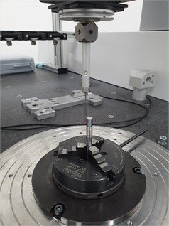
The measurement principles were established according to the measurement instructions of ZEISS. According to these instruction, the correct parameters were chosen for the given purpose. The measurement speed was 3 m.s-1, minimum count of measured points on measured circle was 500 and the circle cutout was 360°. A software function was used to eliminate residual values as well as filters to smooth out local extremes.
2.4. Measurement on GOM ATOS triple scan
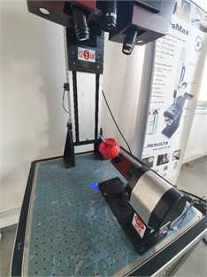
Experimental work was carried out at the Centre of Excellence for Five-Axis Machining at the Faculty of Materials Science and Technology in Trnava, Slovak University of Technology in Bratislava. GOM ATOS triple-scan optical 3D scanning system was used for another set of measurements of the carbide rod. On the scanner head were installed 35 mm objective lenses and the scanner was calibrated for the measuring volume MV38 (38×29×15 mm). Scanner has SO (Small Objects) configuration with one projector and two cameras. The whole optical system had to be warmed up first to be in operational condition. Warming up takes approximately 15 minutes. The first step was the installation of the objective lenses and calibration of the chosen measuring volume. A rotary table with a calibrating grid was used for the calibration process. The camera focus and projector focus as well as the camera polarization filter were adjusted for the best contrast of the rod surface. Parameters of the capture were set to full resolution, normal exposition time, and high quality of scan. The preparation of the rod was identical to that for the touch probe measurement; however, due to the use of structured light when scanning, the reflective surface of the rod had to be made matte by applying titanium powder. Before the powder application, calibrated reference points of 0.4 mm diameter were attached to the surface in such a manner that they would not influence the diameter measurement. When the rod was prepared for scanning, it was clamped in a three-jaw chuck attached to a rotary table. While the plastic chuck in which the rod was fixed during the scanning process does not offer comparable rigidity compared to the metal chuck used for the measurement on the CMM machine, it does not present an issue from the standpoint of the measurement. There were no forces exerted on the rod during the scanning and the relative orientation and positioning of the rod was calculated based on the position of the reference points that were placed on the rod itself. The setup can be seen in Fig. 2.
Fig. 2Measuring on the GOM ATOS triple scan
The rod was tilted at an angle and rotated in increments to capture all reference points in the limited measurement volume. Once the scan was complete, the obtained cloud of points was exported into GOM Inspect software, where it was converted into a 3D model that could be measured. Parameters of GOM ATOS Triple Scan measurement are listed in Table 1.
Table 1Measurement parameters of GOM ATOS Triple Scan
Camera resolution | Measuring volume L×W×H [mm] | Measuring point distance [mm] | Measuring distance [mm] | Camera angle [°] |
5 Megapixels (2448×2050) | MV 38 – 38×29×15 | 0,0147 | 490 | 25 |
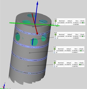
Consequently, the following steps were taken, such as removing redundant scanned features and objects (e.g. chuck), standard mesh polygonization, and postprocessing with more details. As a result of these steps, the digital model of the rod was exported in .stl (stereolitography) file format. The diameter of the rod was evaluated in four sections which were constructed virtually in the software at defined distances (2 mm, 6 mm, 10 mm, 14 mm) from the reference circular plane on the rod as shown in Fig. 3. To each this section was fitted one circle using Gaussian method of creation (least squares method) with 3 sigma used points (99,73 % of obtained points at specific section on the surface are used for evaluation and creation of the circle). Finally, the circle was generated, and its dimensions and circularity were checked. GOM Inspect software was used to evaluate these parameters.
Fig. 3Diameter dimensions in GOM inspect software
3. Results
All obtained data were evaluated and compared. On the basis of the technical parameters of the measurement systems used in the experiment, it is clear that the most accurate result will be produced by the touch probe measurement on the coordinate measuring machine. Therefore, the values obtained on this machine were used as reference values to which optical 3D scanner was compared.
3.1. Comparison of accuracy of different devices
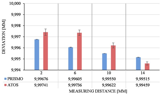
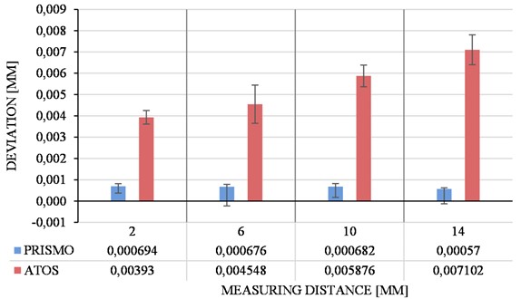
Measured values of the diameter of the carbide rod in four distances from the top of the rod are listed in Fig. 4. Each measurement was repeated five times on every distance with average values and standard deviations calculated.
Fig. 4Measured diameter values
3.2. Evaluation of geometrical tolerance of circularity
Measured values of the circularity of the carbide rod in four distances from the top of the rod are listed in Fig. 5. Each measurement was repeated five times on every distance and standard deviation of the measurement was calculated.
Fig. 5Measured ovality values
4. Discussion
The aim of the research was to verify the possibilities of using an optical 3D scanner for measuring cutting tools. For the purpose of the experiment a cemented carbide rod workpiece was used instead of a cutting tool, which is used for the production of cutting tools by means of grinding. On multiple levels the diameter of the carbide rod was measured as well as circularity. In the case of cutting tools, especially cutting mills, the shape of these tools is different with more complex shape. It can be surmised that there will be no significant difference in accuracy, regardless of the shape being measured. From this point of view, it can be assumed that the 3D optical scanning method is suitable for measurement of cutting tools in terms of macro-geometry.
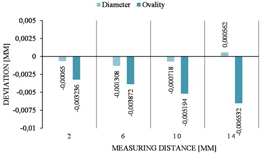
Overview of the deviations of average values obtained by the 3D optical scanner are illustrated in Fig. 6. It can be seen that the deviations of dimensional accuracy are at least an order of magnitude lower than the geometrical tolerancing of ovality. This means that while measuring the dimensions it is possible to achieve sufficient accuracy when it comes to measuring cutting tool parameters on the level of macro-geometry, when evaluating the shape however, the deviations can negatively influence the measurement output.
Fig. 6Deviations of optical 3D scanner values from tactile measurement
Further research could focus on verification the optical 3D scanner for measuring complex cutting tools. This method could be compared to tactile shape and contour measuring machine when measuring micro-geometry of cutting tools or used for measuring tool wear. Considering the achieved accuracy, it could be assumed that it will not be sufficient for very small dimensions of rounding or chamfering on the level of tool microgeometry. Regarding the measurement of tool wear, the measured values will most likely not exceed those of the uncertainty of measurement, therefore using general purpose 3D optical scanning system is not recommended for this task.
5. Conclusions
To sum up the experiment described in the paper, a cemented carbide rod with a diameter of 10 mm and tolerance of h5 was used as a specimen for measurement by two different systems. The rod was cleaned in ultrasonic cleaner and measured on a ZEISS Prismo coordinate measuring machine and then on an optical 3D scanner, GOM ATOS Triple Scan. The goal of the experiment was to verify the possibility of using an optical 3D scanner for measuring macro-geometry of cutting tools. Before measurement on any system, it is of course necessary to calibrate the device, but the calibration time for both compared measurement systems is very similar. There were four measured levels on the carbide rod. The first level was at 2 mm distance from the top face of the rod, and then every four millimeters was an-other distance of up to 14 mm. For statistical evaluation, five measurements were carried out on every distance. Identical carbide rod was used for both measuring devices to minimize the error of measurement. In case of optical 3D scanner there were 5 STL models created after scanning and on each of these models the dimensions and circularity were evaluated on the same levels. From the values obtained, standard deviations and average values were evaluated.
The variation of the dimensional values for both devices was minimal, however for the shape measurement the deviations were substantially higher. From the obtained results, it can be said that optical 3D scanner GOM ATOS Triple Scan is suitable for measuring cutting tools with sufficient accuracy. The main advantage of measuring on ZEISS Prismo is that it is not necessary to apply matte powder on the surface of the measured object and the measurement time is also low. On the other hand, GOM ATOS Triple Scan can capture the entire surface of the measured object, allowing for more complex evaluation of dimensions as well as geometrical characteristics, which is more suitable for the quick measurement and evaluation of cutting tools.
References
-
B. Ramamoorthy and V. Radhakrishnan, “Computer-aided inspection of cutting tool geometry,” Precision Engineering, Vol. 14, No. 1, pp. 28–34, Jan. 1992, https://doi.org/10.1016/0141-6359(92)90139-n
-
C. C. D. Resende et al., “Influence of operator experience, scanner type, and scan size on 3D scans,” The Journal of Prosthetic Dentistry, Vol. 125, No. 2, pp. 294–299, Feb. 2021, https://doi.org/10.1016/j.prosdent.2019.12.011
-
I. V. Surkov, “Development of methods and means of coordinate measurements for linear and angular parameters of cutting instruments,” Measurement Techniques, Vol. 54, No. 7, pp. 758–763, Oct. 2011, https://doi.org/10.1007/s11018-011-9800-2
-
A. Woźniak, R. Mayer, M. Bałaziński, and M. Côté, “Investigation on precise measurement of cutting tool edges using coordinate measuring machines,” in CIRP 2nd High Performance Cutting Conference, 2006, https://doi.org/10.13140/2.1.2586.7522
-
G. Berkovic and E. Shafir., “Optical methods for distance and displacement measurements,” Advances in Optics and Photonics, Vol. 4, pp. 441–471, 2012.
-
J. Valíček et al., “Non-contact method for surface roughness measurement after machining,” Measurement Science Review, Vol. 12, No. 5, pp. 184–188, Jan. 2012, https://doi.org/10.2478/v10048-012-0028-3
-
B. Gapinski, M. Wieczorowski, L. Marciniak-Podsadna, B. Dybala, and G. Ziolkowski, “Comparison of different method of measurement geometry using CMM, optical scanner and computed tomography 3D,” Procedia Engineering, Vol. 69, pp. 255–262, 2014, https://doi.org/10.1016/j.proeng.2014.02.230
-
J. Vagovský, I. Buranský, and A. Görög, “Evaluation of measuring capability of the optical 3D scanner,” Procedia Engineering, Vol. 100, pp. 1198–1206, 2015, https://doi.org/10.1016/j.proeng.2015.01.484
-
J. Peterka, L. Morovič, P. Pokorný, M. Kováč, and F. Hornák, “Optical 3D scanning of cutting tools,” Applied Mechanics and Materials, Vol. 421, pp. 663–667, Sep. 2013, https://doi.org/10.4028/www.scientific.net/amm.421.663
-
R. Mendricky and O. Langer, “Influence of the material on the accuracy of optical 3D digitalisation,” MM Science Journal, Vol. 2019, No. 1, pp. 2783–2789, Mar. 2019, https://doi.org/10.17973/mmsj.2019_03_2018121
-
R. Mendricky and V. Kafka, “Analysis of the accuracy of virtual clamping in the field of 3D scanning,” MM Science Journal, Vol. 2021, No. 1, pp. 4244–4253, Mar. 2021, https://doi.org/10.17973/mmsj.2021_03_2020068
-
I. Česáková, M. Zetek, and V. Švarc, “Evaluation of cutting tool parameters,” Procedia Engineering, Vol. 69, pp. 1105–1114, 2014, https://doi.org/10.1016/j.proeng.2014.03.098
-
D. Palousek, M. Omasta, D. Koutny, J. Bednar, T. Koutecky, and F. Dokoupil, “Effect of matte coating on 3D optical measurement accuracy,” Optical Materials, Vol. 40, pp. 1–9, Feb. 2015, https://doi.org/10.1016/j.optmat.2014.11.020
-
D. Chan, A.-H. Chung, J. Haines, E.-T. Yau, and C.-C. Kuo, “The accuracy of optical scanning: influence of convergence and die preparation,” Operative Dentistry, Vol. 36, No. 5, pp. 486–491, Oct. 2011, https://doi.org/10.2341/10-067-l
-
R. Mendřický, “Determination of measurement accuracy of optical 3D scanners,” MM Science Journal, pp. 1565–1572, 2016, https://doi.org/10.17973/mmsj.2016
-
A. Weckenmann and K. Nalbantic, “Precision measurement of cutting tools with two matched optical 3D-sensors,” CIRP Annals, Vol. 52, No. 1, pp. 443–446, 2003, https://doi.org/10.1016/s0007-8506(07)60621-0
-
S. H. Jang, Y. Shimizu, S. Ito, and W. Gao, “A micro optical probe for edge contour evaluation of diamond cutting tools,” Journal of Sensors and Sensor Systems, Vol. 3, No. 1, pp. 69–76, Mar. 2014, https://doi.org/10.5194/jsss-3-69-2014
-
R. Danzl and F. Helmli, Geometry and Wear Measurement of Cutting Tools. 2007.
-
F. Helmli, R. Danzl, and S. Scherer, “Optical measurement of micro cutting tools,” Journal of Physics: Conference Series, Vol. 311, No. 1, p. 012003, Aug. 2011, https://doi.org/10.1088/1742-6596/311/1/012003
-
P. Hidnert, “Thermal expansion of cemented tungsten carbide,” Journal of Research of the National Bureau of Standards, Vol. 18, pp. 47–52, 1937.
-
F. J. Fuchs, “Ultrasonic cleaning: fundamental theory and application,” NASA. Marshall Space Flight Center, Aerospace Environmental Technology Conference, Sep. 2013.
About this article

This work supported by research project Development of new progressive cutting tools for machining parts produced by WAAM additive manufacturing technology to reduce the number of cutting tools when machining parts from different types of materials, (ITMS2014+: 313011BWQ8) supported by the Operational Programme Integrated Infrastructure funded by the European Regional Development Fund.
The datasets generated during and/or analyzed during the current study are available from the corresponding author on reasonable request.
Boris Pätoprstý was responsible for conceptualization, methodology and writing – original draft preparation. Marek Vozár was responsible for data curation, visualization and writing – review and editing. Róbert Hrušecký was responsible for investigation, supervision, resources and validation. And Ivan Buranský was responsible for formal analysis, project administration and funding acquisition.
The authors declare that they have no conflict of interest.
