Abstract
In order to detect and diagnose the operating status without disassembling automobile parts, engine speed and suspension status were tested and analyzed based on vibration detection technology. Based on a DSP processor and an acceleration sensor, the speed of a single cylinder engine was tested under steady-state and transient conditions, respectively. Using the cepstrum method, the vibration signals were collected at different speeds are processed, the fundamental frequency was extracted, and the engine speed information was obtained. According to the speed verification using the Otsu EWT method, the maximum relative error of engine speed was less than 1.5 %, and the error decreases as the speed increases. In order to ensure the reliability of suspension vibration signals, the overall structure and safety of the vibration characteristic detection scheme were designed. Due to the limited sampling frequency of suspension load status sensor data, the EMD method was adopted to process dynamic load signals, which had a good separation effect on suspension vibration signals.
Highlights
- Based on a DSP processor and an acceleration sensor, the speed of a single cylinder engine was tested under steady-state and transient conditions, respectively.
- Using the cepstrum method, the vibration signals were collected at different speeds are processed, the fundamental frequency was extracted, and the engine speed information was obtained.
- Due to the limited sampling frequency of suspension load status sensor data, the EMD method was adopted to process dynamic load signals.
1. Introduction
The operating status of a car is of great significance for predicting and determining faults. With the development and application of testing technology, the detection of key automotive components based on vibration signals has become a hot research topic in the industry [1, 2]. The vibration signal generated by the engine during operation has a corresponding functional relationship with the engine speed, and monitoring of operating parameters such as engine speed can be achieved through the fluctuation and variation of the vibration signal generated by the engine [3]. Timely detect faults during engine operation to prevent accidents from occurring. When the speed is constant, the phase trajectory is distributed in the closed zone, and the suspension dynamic travel and dynamic load phase points form a quasi periodic oscillation stable state [4]. Moreover, as the vehicle’s loading weight increases, the vibration amplitude of the suspension dynamic travel and dynamic load both significantly increases [5]. Therefore, through the detection of vibration signals, the working state of the suspension can be effectively obtained. The load on the internal components of the car engine and suspension during operation also changes due to changes in engine operating conditions. The requirements for condition detection, fault diagnosis, and other aspects of car driving are correspondingly increased. In order to solve the shortcomings of traditional detection and diagnosis technology such as time-consuming and complex operation, modern engine detection and diagnosis technology has emerged with the help of the development achievements of electronic and computer technology. Modern vibration detection and diagnosis technology is fundamentally different from traditional manual inspection and diagnosis [6]. It achieves detection and diagnosis without dismantling equipment on the basis of easily measurable physical quantities such as vibration signals, and has good economic and social benefits.
2. Detection and analysis of engine running state
2.1. Engine speed detection scheme
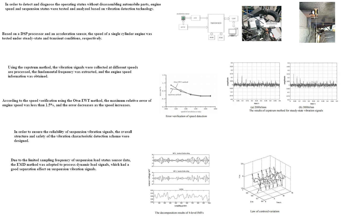
During engine operation, when energy conversion is completed, the mixture of fuel and air needs to be mixed in a certain proportion to form a mixed gas that enters the cylinder through the intake valve. The volume of this mixed gas is compressed by the upward movement of the piston, and the ignition device of the engine is activated. The high-temperature and high-pressure gas generated by the compression ignition combustion of the mixture generates a strong driving force that directly acts on the top of the piston. The linear motion pushes the piston downwards, causing the crankshaft flywheel mechanism connected to the piston to rotate and do work, outputting mechanical energy to the outside world, thereby completing the conversion from chemical energy to mechanical energy. On the other hand, the rotation of the crankshaft flywheel mechanism, under the action of inertia, will drive the piston to move in a reciprocating straight line. During the movement process, as the engine exhaust valve, intake valve, and ignition device open and close, the piston can undergo uninterrupted reciprocating linear motion, generating continuous power supply to the outside world through the connecting rod and crankshaft flywheel mechanism. During engine operation, the total torque generated by fuel combustion in the cylinder and the inertia force of the crankshaft connecting rod mechanism can cause internal torque imbalance in the engine. This unbalanced torque can be transmitted to structures such as brackets through the engine body and crankshaft bearings, causing vibration. The centrifugal inertia force has zero torque on the crankshaft, and the reciprocating inertia force caused by piston movement will generate tangential torque on the crankshaft through the connecting rod. The periodic changes caused by this tangential torque will cause torsional vibration. The impact force generated by gas explosion in the engine cylinder exerts time-varying forces on other positions of the engine. Therefore, transient dynamic analysis can be used to obtain the vibration situation of various components of the engine. By using the modal superposition method to calculate the vibration of various engine components, it can be concluded that the vibration signal of each engine component caused by the reciprocating linear motion of the piston is a complex function composed of the fundamental frequency signal, its higher-order harmonics, and the surrounding environmental noise signal. In the speed measurement experiment of a single cylinder engine based on DSP processor, a single axis vibration acceleration sensor was selected to collect the vibration signal of the engine bench position, as shown in Fig. 1.
Fig. 1Sensor detection principle and installation position

2.2. Testing under steady-state conditions
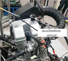
In the steady-state speed measurement experiment of a single cylinder engine, the cepstrum method is used to process the vibration signals collected at each speed, extract the fundamental frequency, and obtain engine speed information. The cepstrum processing results of vibration signals at speeds of 2000 r/min and 3000 r/min are shown in Fig. 2. It can be seen that when the engine is operating under steady-state conditions, the cepstrum method can convert each harmonic component signal into a single spectral line on the cepstrum. The time interval between adjacent spectral lines is the period of the vibration signal, and the fundamental frequency information can be obtained by taking the reciprocal of the period. Under various two experimental speed conditions, the maximum relative errors of engine speed extracted using the cepstrum method are 1.1 % and 0.9 %, respectively.
Fig. 2The results of cepstrum method for steady-state vibration signals
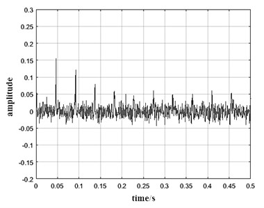
a) 2000 r/min
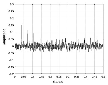
b) 3000 r/mn
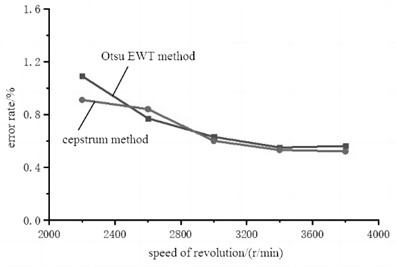
After using the cepstrum method to extract the fundamental frequency information of engine vibration signals at different speeds, the Otsu EWT method can be used on the upper computer to verify the error of the vibration signal, as shown in Fig. 3. When the engine is running under steady-state conditions, the maximum relative error of the engine speed obtained by processing the engine vibration signal is within 1.5 %, and the error gradually decreases as the speed increases.
Fig. 3Error verification of speed detection
2.3. Testing under unsteady-state conditions
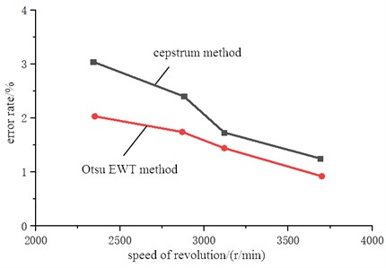
Under non steady state operating conditions, engine speed measurement experiments were conducted within the speed range of 2000 to 4000 r/min. The cepstrum method and Otsu EWT method are used to process the collected vibration signals, extract the fundamental frequency information, and obtain the engine speed. When the engine operates under non-stationary conditions, the cepstrum method treats the vibration signal during the entire selected time as a quasi periodic signal processing, with spectral lines on the cepstrum, thus reflecting the continuous time-frequency characteristics of the signal, as shown in Fig. 4. The error verification results of the speed extraction are shown in Fig. 5. It can be seen that the large relative error of the speed obtained after processing the engine vibration signal using the cepstrum method is relatively large, with a maximum of 3.04 %. The maximum relative error of the speed measured by the Otsu EWT method is 2.03 %.
Fig. 4The unsteady-state vibration signals
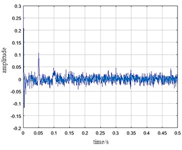
Fig. 5Comparison of errors in speed extraction
3. Detection and analysis of suspension status
3.1. Analysis of bearing failure cost and detection effect
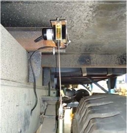
In order to ensure the reliability of suspension vibration signals, the overall structure and installation position of the suspension characteristic detection device have been set up, as shown in Fig. 6. The overload protection mechanism component is connected to the cable displacement sensor through a connecting steel wire. The cable displacement sensor is connected to the vehicle body connecting plate through sensor connecting bolts, and to the side beams on both sides of the rear axle frame through the vehicle body connecting plate. The overload protection mechanism assembly is connected to the rear axle steel plate spring connecting plate through a mechanism fastening device, and the rear axle steel plate spring connecting plate is connected to the steel plate springs on both sides of the rear axle. When the vehicle is loaded, due to the relative displacement between the frame and axle caused by the load, the expansion and contraction of the sensor cable will also change. Cable displacement sensors can convert mechanical displacement into measurable linear proportional electrical signals. Using the characteristics of cable sensors to measure the voltage output of vehicles at different load levels, establish the relationship between the vertical load of each tire of the vehicle and the output voltage of the cable displacement sensor.
Fig. 6Suspension vibration detection
Due to the limited sampling frequency of suspension load state sensor data, it is not possible to sample low-frequency dynamic loads with complete cycles. In this case, traditional filtering methods cannot quickly and effectively separate dynamic loads. For the processing of nonlinear periodic dynamic load signals, the EMD method is used to process dynamic load signals.
3.2. Processing and analysis of vibration signals
EMD method is a time-domain signal processing method that can effectively decompose a series of nonlinear and non-stationary signals. This method believes that any signal can be synthesized by a series of different intrinsic mode functions, so it can decompose complex signals into a finite number of IMFs. The decomposed IMF components contain local feature signals of the original signal at different time scales. The IMF with the lowest frequency is called a steady-state quantity, representing the trend or mean of the original signal, while the other IMF orders reflect the dynamic characteristics of the signal. In the process of processing dynamic load signals of automobiles, the static axle load of automobiles is regarded as a steady-state quantity, and the dynamic load is regarded as an intrinsic mode function in the signal. By separating the dynamic load from the vehicle load signal using the EMD method, the static axle load of the vehicle can be obtained. To achieve effective feature analysis of load measurement signals, it is necessary to choose suitable signal processing methods. Taking the analysis of the amplitude frequency characteristics of sensor signals during vehicle driving at a speed of 40 km/h as an example, the voltage signal collected by the sensor installed on the left front suspension is shown in Fig. 7. The frequency spectrum characteristics of the signal are obtained by Fourier transform, as shown in Fig. 8. It can be seen that the sensor signal is composed of waveform superposition of multiple frequencies, and the main frequency is not obvious. So, considering the characteristics of the sensor voltage signal comprehensively, the EMD method is used to process the dynamic load signal.
Fig. 7Voltage signal collected by the sensor
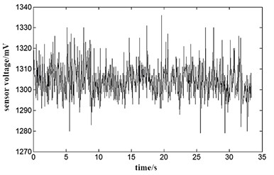
Fig. 8The frequency spectrum characteristics
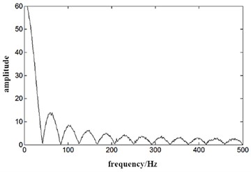
Fig. 9The decomposition results of 4-level IMFs
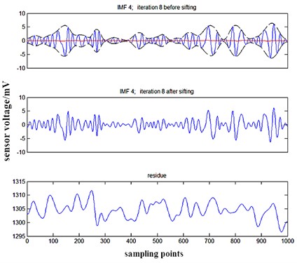
Fig. 10Law of centroid variation
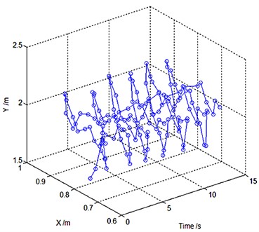
The maximum number of IMF extracted during the process of removing dynamic parts from signals based on EMD method is set to 4. The maximum number of iterations for extracting each IMF is set to 20. As shown in Fig. 9, the decomposition results of 4-level IMFs after EMD iteration can accurately separate different types of dynamic signals. Based on EMD decomposition and removal of some residual dynamic loads, the motion law of the center of mass can be obtained as shown in Fig. 10. The residual amount includes the static reference value of suspension deformation and some dynamic characteristics. The analysis results retain some dynamic characteristics rather than directly calculating static values, taking into account the impact of road conditions on dynamic loads, making the obtained load state information more accurate.
4. Conclusions
When using traditional methods for vehicle condition detection, many parts need to be disassembled, resulting in low detection efficiency. The measurement and parameter extraction method based on vibration signals can effectively obtain the working status and parameters of key components, which has good feasibility and accuracy. To ensure the stability of sensor data processing, the TMS320F28335 chip was used as the core processor. The error of the collected vibration signal was compared and verified through the cepstrum method and Otsu EWT method, and the research scheme was verified to have good reliability. Taking into account the characteristics of sensor voltage signals, the EMD method is used to process dynamic load signals, which can effectively extract effective data and ensure the accuracy of suspension vibration detection. By tracking the position of the center of mass, the distribution of load states and weight transfer can be monitored, providing a basis for identifying dangerous states such as vehicle suspension failure. It should be noted that the testing of engine speed in the paper is based on vibration signals, but is not used for online detection of the vehicle itself. Instead, it is used for offline detection at repair stations or maintenance shops as a reference and basis for related faults.
References
-
Y. Wang, V. Jagota, M. E. Makhatha, and P. Kumar, “Vibration signal acquisition and computer simulation detection of mechanical equipment failure,” Nonlinear Engineering, Vol. 11, No. 1, pp. 207–214, Jun. 2022, https://doi.org/10.1515/nleng-2022-0026
-
M. H. M. Ghazali and W. Rahiman, “An Investigation of the Reliability of Different Types of Sensors in the Real-Time Vibration-Based Anomaly Inspection in Drone,” Sensors, Vol. 22, No. 16, p. 6015, Aug. 2022, https://doi.org/10.3390/s22166015
-
Y. Jia and Y. Hu, “Research on fault signal detection method of mechanical vibration based on Kalman filtering algorithm,” International Journal of Information and Communication Technology, Vol. 1, No. 1, pp. 272–289, 2022, https://doi.org/10.1504/ijict.2022.10044157
-
Z. Feng, H. Ma, and M. J. Zuo, “Vibration signal models for fault diagnosis of planet bearings,” Journal of Sound and Vibration, Vol. 370, No. 1, pp. 372–393, May 2016, https://doi.org/10.1016/j.jsv.2016.01.041
-
R. Bouhali, K. Tadjine, H. Bendjama, and M. N. Saadi, “Fault diagnosis of bladed disc using wavelet transform and ensemble empirical mode decomposition,” Australian Journal of Mechanical Engineering, Vol. 18, No. sup1, pp. S165–S175, Jul. 2020, https://doi.org/10.1080/14484846.2018.1499471
-
B. D. Kshirsagar, S. C. Goud, and S. N. Khan, “Vibration analysis of femur bone by using consistent mass matrices and fast Fourier transform analyzer,” Materials Today: Proceedings, Vol. 26, No. 2, pp. 2254–2259, 2020, https://doi.org/10.1016/j.matpr.2020.02.489
About this article

The authors have not disclosed any funding.
The datasets generated during and/or analyzed during the current study are available from the corresponding author on reasonable request.
The authors declare that they have no conflict of interest.
