Abstract
Bearings play a crucial role in the functionality of rotating machinery, and any defects in these components can result in machine failure. Detecting, diagnosing, and prognosing bearing faults are crucial steps in machine failure diagnostics to prevent malfunctions and breakdowns. While various methods exist for fault detection, including acoustic emission analysis, visual inspection, thermography, ultrasonic, motor current analysis, wear-debris analysis, oil analysis, and vibration analysis, the latter stands out as a popular non-destructive method. This paper focuses on time and frequency domain vibration analysis techniques for detecting faults in floating bush bearings. Particularly beneficial for online monitoring, remote and non-human intervention areas, and hazardous locations, the time-frequency domain approach enhances diagnostic capabilities. The vibration data collected during these experiments has been rigorously analyzed using data acquisition system and applied a comprehensive approach that includes evaluating the data in both the time and frequency domains, as well as utilizing advanced signal processing techniques, notably the high-frequency resonance technique. Test results underscore the effectiveness of specific parameters in identifying defects: waveform, form factor, parameter K, and cepstrum excel in pinpointing external defects, while kurtosis, crest factor, and skewness prove adept at identifying internal faults. In the frequency domain, the enveloped spectrum emerges as a robust method for comprehensive defect detection. The vibration data presented in this paper will prove to be an invaluable resource for professionals engaged in the field of vibration measurement and analysis.
1. Introduction
The bearing stands as a critical component within engineering machinery, and even the slightest impairment can result in unforeseen disruptions to production, potentially leading to industrial accidents. Various factors contribute to the emergence of common bearing faults, including but not limited to unpredictable heavy loads and inadequate lubrication. Recognizing these defects before they escalate is of paramount significance. Typically manifesting in bearing elements like inner and outer side, faults tend to evolve during the operational life of the bearing. Timely diagnosis of these faults during their early stages is imperative to ensure proactive maintenance and prevent potential setbacks. A floating bush bearing, characterized by a thin bush that moves freely between a journal and a fixed bush, was the subject of investigation in this study. To explore the vibration characteristics of floating bush bearings, an experimental setup was meticulously designed. Initially, the study involved the testing of ten distinct floating bush bearings to assess their vibration attributes. Noteworthy research by Tandon et al. [1] comprehensively delves into various diagnostic methods, including vibration measurements in both time and frequency domains, sound measurements, the shock pulse method, and the acoustic emission technique. These techniques are crucial for condition monitoring in rolling element bearings, focusing on vibration and acoustics. Kim et al. [2] have also examined a range of vibration and wear debris analysis methods, such as vibration, shock pulse, spike energy, spectrographic oil analysis, ferrography, and chip detection, with a particular emphasis on their application in railway freight cars. Mathew et al. [3] provided a brief review of vibration monitoring techniques in time and frequency domains, primarily focusing on rolling element bearings. Furthermore, McFadden et al. [4-6] have offered valuable insights into the most effective techniques employed in condition monitoring of rolling element bearings. Hence, this study aims to build upon and interpret these reviews by incorporating the results of vibration experiments on floating bush bearings, with a specific focus on defect detection. Floating bush bearings are susceptible to various defects, such as pits, dents, and ovality, often resulting from wear and tear. Dolenc et al. [7-10] have proposed methods based on the analysis of vibration signals, which have proven to be effective in recent years. The concept of distributed faults, typically stemming from irregularities in bearing geometry due to imperfect manufacturing, faulty mounting, or bearing misuse, has been explored by Sopanen et al. [11-12]. In this study, distributed faults refer to bearing surface defects spread over a large area, with two or more rolling elements possibly located within the faulty area simultaneously. Mathew et al. [3] employed the probability density function method (PDF) for data analysis. Since a bearing acceleration signal exhibits random and Gaussian characteristics, its skewness is inherently zero. To utilize skewness as a diagnostic parameter, Honarvar et al. [13, 14] proposed a method for rectifying the vibration signal to attain non-zero skewness. However, in this study, skewness was calculated without implementing the method suggested in [15], as it was observed that defective floating bush bearings exhibited non-zero skewness even without signal rectification. This section presents the results of the analysis using various time-domain parameters.
The vibration data in this paper were analyzed using a range of techniques, including peak to valley, RMS level, skewness, kurtosis, enveloped spectrum, and peak ratio, among others. These parameters were compared to provide diagnostic insights. The study employed both time and frequency domain vibration data to identify defects in bearings comprehensively. The findings indicated that, in the time-domain, time-waveform, form factor, parameter K, and cepstrum serve as effective indicators for detecting outer side defects in floating bush bearings. Conversely, kurtosis, crest factor, and skewness are reliable indicators for identifying inner side defects. In the frequency domain, peak ratios are primarily suited for diagnosing outer side defects. Utilizing the vibration data, various types of defects were clearly discernible through enveloping. In conclusion, while various diagnostic parameters are valuable for defect detection, a comprehensive understanding of bearings’ condition requires the joint utilization of time and frequency domain information.
This paper introduces a novel technique for analyzing vibrations in the time-frequency domain to detect faults in floating bush bearings. The proposed method addresses concerns related to inner, outer, and dual-sided occurrences of faults in the floating bush. Vibration signals are systematically gathered through suitable data acquisition systems and transducers, with a primary focus on capturing information in the time domain.
2. Experimental methodology
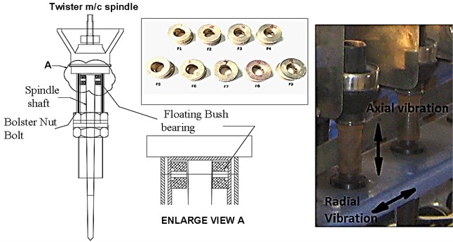
This paper presents the results of experiments conducted on floating bush bearings aimed at diagnosing defects through the utilization of time and frequency domain methodologies. To facilitate this investigation, a testing setup was established for evaluating various floating bush bearings (F1-F9). The setup was constructed using a vertical spindle from a textile machines twister apparatus, with the goal of exploring the vibration characteristics, as depicted in Fig. 1.
The radial and axial vibrations of the test spindle frame were meticulously captured using a stud-mounted accelerometer (Vibscanner FFT module) affixed to the machine frame, operating at a specified speed. These vibration signals were subsequently transmitted to a computer for processing with various parameters.
For the defect-free bearings, vibration data were obtained at three distinct speeds: 166 Hz, 255 Hz, and 333 Hz, which collectively encompass the operational range of the majority of machines that employ floating bush bearings. Data acquisition was performed in two frequency ranges: 0-1 kHz and 0-10 kHz, ensuring that both high and low-frequency information was available with ample resolution. Subsequently, the acquired data underwent further processing to derive a range of time and frequency parameters.
Fig. 1Floating bush bearing and its location in twister spindle
3. Results and Discussions
3.1. Time Domain vibration analysis
Figures 2 to 3 display the results obtained for peak-to-valley, RMS vibration level, crest factor, form factor, skewness, kurtosis, and parameter K, concerning axial and radial vibrations within the two frequency ranges employed. In each of these plots, various parameters for the defective bearings are juxtaposed with the corresponding parameters of the defect-free bearings. The values for the defect-free bearings represent the average of seven distinct vibration records obtained over a period of time. Within these plots, F0 denotes the defect-free bearing, while F1 through F9 represent the defective bearings, each with specific defects on the inner side, outer side, or a combination of both, as detailed in Table 1.
Table 1Defect size of test bearing
Sr. No. | Defect location | Defect diameter (mm) | Defect depth (mm) | Remark |
F0 | No defect | |||
F1 | Outer side | 0.15 | 0.05 | One defect |
F2 | Outer side | 0.25 | 0.1 | One defect |
F3 | Outer side | 0.5 | 0.15 | One defect |
F4 | Outer side | 0.15& 0.5 | 0.05&0.15 | Two defects |
F5 | Inner side | 0.15 | 0.05 | One defect |
F6 | Inner side | 0.25 | 0.1 | One defect |
F7 | Inner side | 0.5 | 0.15 | One defect |
F8 | Inner side | 0.15&0.5 | 0.05&0.15 | Two defects |
F9 | Outer + Inner side | 0.50&0.50 | 0.15&0.15 | Two defects |
3.1.1. Peak to valley
As evident from Figs. 2 and 3, the peak-to-valley values of measured acceleration exhibit higher values for axial vibration in comparison to radial vibration across the spectrum of floating bush bearings (F0-F9). Notably, this difference is more pronounced for the defective bearings. This divergence can be attributed to the fact that axial vibration, in both frequency ranges used (0-1 kHz and 0-10 kHz), contains certain peaks associated with the natural frequencies of the rotor-bearing unit. As a consequence, the axial vibration displays higher peak values, as illustrated in Figs. 2 and 3. This observation can be validated through frequency domain analysis.
Fig. 2Peak values for floating bush bearing with defect on outer side
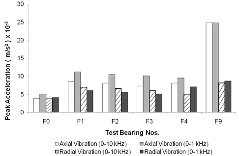
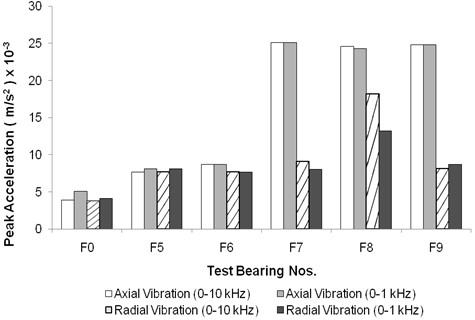
Fig. 3Peak values for floating bush bearing with defect on inner side
Moreover, it is evident that when compared to the peak-to-valley values of the defect-free bearing (F0), the defective bearings (F1-F9) consistently exhibit higher peaks in acceleration amplitude. This phenomenon is unsurprising, as defective bearings produce an impact during the contact between the defect and the bush surfaces. The magnitude and duration of these impacts vary according to the location and size of the defect. In the case of floating bush bearings with outer side defects (F1-F4), the peak-to-valley values of acceleration are most pronounced for the smallest defect size tested (Bearing F1). Interestingly, there isn't a continuous increase in peak amplitudes of acceleration with the increase in the size of defects on the outer side.
Observing Fig. 2, it becomes evident that for axial vibration, the high-frequency vibration range (0-10 kHz) yields higher peak values than the low-frequency vibration range (0-1 kHz). Conversely, for radial vibration, low-frequency vibrations exhibit higher peak values compared to high-frequency vibrations. This discrepancy arises because the high-frequency (0-10 kHz) axial vibration encompasses several resonances of the bearing assembly. This conclusion is corroborated by impact tests and the presence of speed-independent frequency peaks in the high-frequency spectrum for axial vibration, which are observed by running the test bearings at various speeds. Fig. 3 illustrates the vibration peak levels for floating bush bearings with inner side defects. The peak levels for both radial and axial vibration are nearly identical within the two frequency ranges for bearings F0, F5, and F6. However, bearings F7 to F9 exhibit higher axial vibration peaks, with only bearing F8 displaying higher peak levels in radial vibration compared to the other bearings. Notably, for the bearing with two defects (F8), the peak values are significantly higher than those for bearings with single defects (F5-F7). This difference is attributed to the fact that the bearing (F8) with two point defects generates more impacts than bearings with single defects (F5-F7). With each rotation of the shaft, the impacts at two locations combine to produce higher vibration peaks.
To identify a distinguishing feature that can signify the presence of two point defects in bearing F8, the waveforms of bearing F8 and bearings F5-F7 were compared. It was observed that the waveform of bearing F8 closely resembled that of bearings F5-F7, with the sole distinction being the higher peak-to-valley value, which served as an indicator of the two defects in bearing F8.
Fig. 4Time-waveform for floating bush bearing with inner side defect
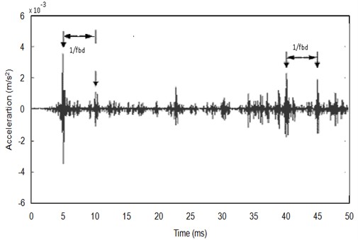
Fig. 5Time-waveform for floating bush bearing with outer side defect
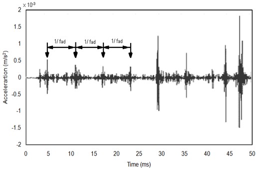
The waveforms of bearings exhibiting outer side defects exhibit a distinct impulsive nature, characterized by impulses that are evenly spaced at the impact repetition rate corresponding to the outer side defect frequency, as illustrated in Fig. 5. This observation aligns with findings by Mathew and Alfredson [3], who also reported equally spaced impulses for outer side defects and randomly spaced impulses for ball defects in self-aligning ball bearings.
It is noteworthy that Bearing F9, which possesses defects on both sides of the floating bush bearing, exhibits higher peak levels than Bearing F4 with two outer side defects, and similar peak levels to Bearing F8. This phenomenon arises because, in the case of multi-point defects, the vibration signal is a composite of various impact signals stemming from distinct defect locations.
Consequently, it becomes evident that higher peak-to-valley values serve as an indicator of the presence of local defects on the outer side in floating bush bearings. However, it is important to note that a direct correlation between peak-to-valley values and the size of the defect is not readily discernible.
3.1.2. Overall vibration level (RMS)
The RMS levels of acceleration, as depicted in Fig. 6 and 7, exhibit a similar pattern to that of the peak-to-valley values of acceleration, as observed in Fig. 2 and 3. Fig. 6 highlights that, for each floating bush bearing, the axial vibration levels within the 0-10 kHz range are the highest. In cases of bearings with inner side defects, the axial vibration levels are found to be slightly elevated compared to the corresponding radial vibrations. This discrepancy can be attributed to the presence of bearing system resonances in the high-frequency (0-10 kHz) axial vibration, as previously mentioned when discussing the peak-to-valley values of acceleration.
Fig. 6RMS values for floating bush bearings with defects on outer side
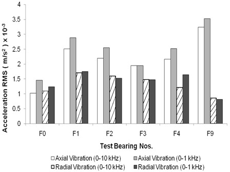
Fig. 7RMS values for floating bush bearings with defects on inner side
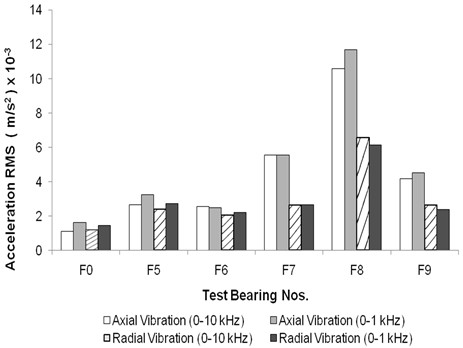
Comparatively, the defective floating bush bearings exhibit higher RMS vibration levels in contrast to the defect-free bearing, a pattern that aligns with expectations. The presence of defects on the bearing sides generates periodic impacts within the bearings, resulting in an overall increase in the vibration levels.
The overall RMS vibration level proves to be a reliable indicator of bearing defects, particularly for outer side defects. This observation corroborates trends observed by Mathew [3] in the context of ball bearings.
3.1.3. Crest factor
Fig. 8 illustrates the variation in crest factor for floating bush bearings afflicted with outer side defects. Surprisingly, no discernible, consistent pattern is observed, and the crest factor ranges from 3.0 to 4.5. This range of crest factor values falls within the expected range for defect-free bearings, thus rendering crest factor ineffective in indicating the presence of outer side defects in floating bush bearings.
Fig. 8Crest factor for floating bush bearing with defects on outer side
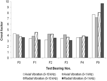
Fig. 9Crest factor for floating bush bearing with defects on inner side
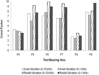
Conversely, Fig. 9 depicts the crest factor variation for floating bush bearings with inner side defects. It notably reveals significantly higher crest factor values (ranging from 6 to 10) for bearings F5-F7 when compared to the defect-free bearing F0. These higher crest factor values serve as a clear indicator of defects within the bearing, a trend in line with the findings reported by Govindappa and Krishnappa [16]. Interestingly, for Bearing F8, which featured two inner side defects, the crest factor is lower than that of the defect-free bearing F0. This discrepancy can be attributed to the fact that, as demonstrated in Figs. 6, 7, Bearing F8 exhibits a more substantial increase in RMS level than in peak-to-valley values, in comparison to all the bearings with inner side defects (F5-F8). Consequently, the ratio, crest factor (peak-to-valley/RMS), decreases for Bearing F8.
For Bearing F9, the crest factor values are comparable to those of bearings with single defects, which is unsurprising as Bearing F9 harbors both inner and outer side defects. In alignment with the observations of Tandon [1], Mathew [3], and Li et al. [18, 19], crest factor emerges as a less reliable parameter for detecting faults in ball bearings. From the presented data, it can be concluded that while high crest factor values may be indicative of defects in floating bush bearings, crest factor alone does not reliably serve as a diagnostic parameter for identifying outer side defects.
3.1.4. Form factor
In the case of floating bush bearings afflicted with defects on the outer side, there is a marked and significant increase (roughly 3-4 times higher) in the form factor when compared to the form factor of defect-free bearings. This phenomenon is consistent in both axial and radial vibrations and across the two frequency ranges employed, as illustrated in Fig. 10.
Fig. 10Form factor for floating bush bearing with defects on outer side
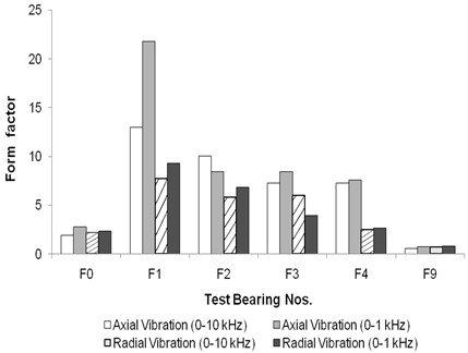
Fig. 11Form factor for floating bush bearing with defects on inner side
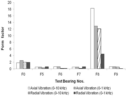
The form factor, interestingly, exhibits a decreasing trend as the size of the defect on the outer side increases. This pattern is attributed to the RMS level, which demonstrates a parallel trend, as depicted in Fig. 6. In contrast, for floating bush bearings with defects on the inner side, the form factor is lower than that of the defect-free bearing, making it an unreliable indicator for inner side defects (as observed in Fig. 11). This is mainly because the RMS level is also lower for bearings with single defects in comparison to bearings with side defects.
For Bearing F9, the form factor values are generally lower in comparison to other bearings with two point defects (F4 and F8). This discrepancy can be attributed to the higher mean value of the acceleration signal in Bearing F9.
In summary, it can be concluded that the form factor proves to be a useful parameter for diagnosing outer side defects exclusively. However, it is not a reliable parameter for identifying inner side defects in floating bush bearings.
3.1.5. Skewness
For a good bearing, the skewness is zero as the vibration signal of a good bearing is Gaussian and random in nature [13, 17]. Skewness is not indicating a clear pattern for floating bush bearings with outer side defects (Fig. 12). In case of floating bush bearings with inner side defects, the skewness is found more than that of the defect-free bearing (Fig. 13).
Fig. 12Skewness for floating bush bearing with defects on outer side
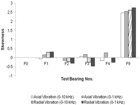
Fig. 13Skewness for floating bush bearing with defects on inner side
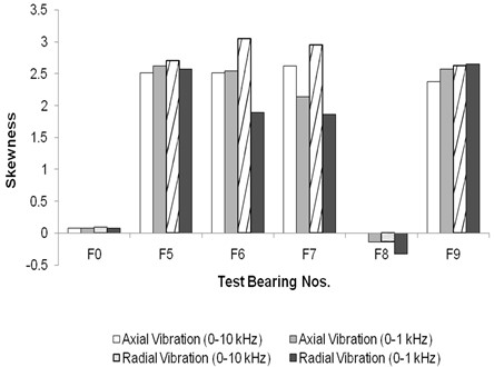
For bearing F8, skewness is negative, as this bearing has two defects on bush spaced 90° apart. For bearing F9, skewness values are 4-5 times than those for other bearings with outer side defects, due to the presence of defects on outer and inner side. From the above it is seen that skewness is a poor indicator of faults on outer side defects.
3.1.6. Kurtosis
In the case of defect-free floating bush bearings (F0) and bearings bearing defects on the outer side (F1-F4), the kurtosis values fall within the range of 2.9 to 2.7, as depicted in Fig. 14. This range of kurtosis values does not provide a clear indication of faults within the bearings. Li et al. [18, 19] have emphasized that kurtosis does not exhibit a consistent pattern.
Fig. 14Kurtosis for floating bush bearing with defects on outer side
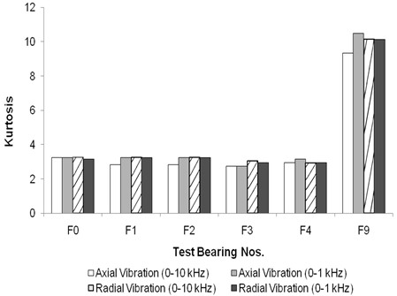
Fig. 15Kurtosis for floating bush bearing with defects on inner side
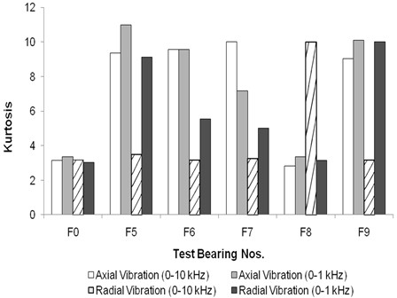
However, for floating bush bearings with inner side defects, as illustrated in Fig. 15, the kurtosis values significantly exceed 3, which serves as a clear indicator of the presence of defects. This observation aligns with the findings of Honarvar and Martin [14] and Mathew & Alfredson [3], who have reported elevated kurtosis values for roller defects in roller bearings compared to outer side defects. Honarvar and Martin [13] have predicted a continuous increase in kurtosis with time as the defect size grows, from the inception of a point defect until failure. However, the results from this study, as well as the findings in reference [3, 17], do not demonstrate this trend.
For Bearing F9, the kurtosis values are higher than those observed in other bearings (Fig. 15), primarily due to the presence of defects on both sides of the floating bush. In this study, the floating bush bearings exhibit the highest kurtosis values generally in the 0-10 kHz axial vibration.
Consequently, while kurtosis may not consistently indicate incipient damage, monitoring kurtosis values in the 0-10 kHz axial vibration range can indeed facilitate the diagnosis of defects in floating bush bearings.
3.1.7. Parameter
values are less than one for all the defective floating bush bearings. For bearings with outer side defects (Fig. 16), the values are in region III ( 0.5 to 0.2) as per Sturm and Kinsky [15] except for the 0-10 kHz radial vibration. These values of lying in region III indicate the presence of damage [15]. For the 0-10 kHz range of data, values are in the region II ( 1 to 0.5) indicating normal running condition.
Fig. 16Parameter K for floating bush bearing with defects on outer side
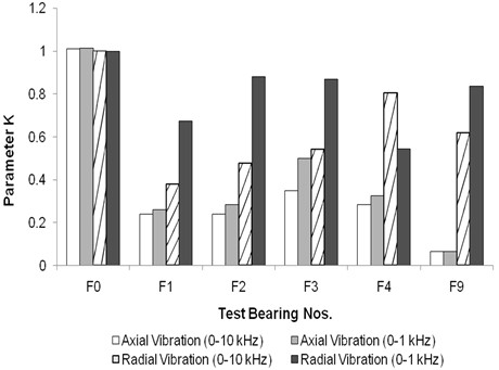
Fig. 17Parameter K for floating bush bearing with defects on inner side
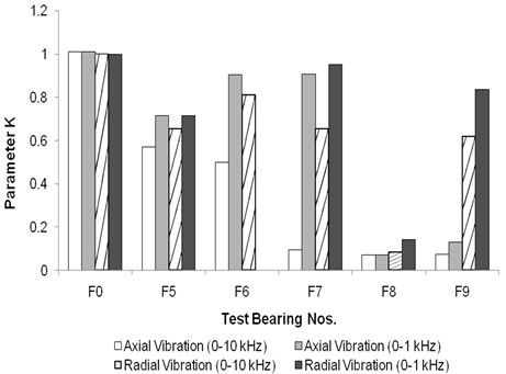
This record seems to be inconsistent with the other vibration records of axial and radial direction. In spite of the presence of defect, it is not indicating a defect. As the outer side defect size increases, the values are also increasing in axial & radial vibration. For bearings with inner side defects (Fig. 17), values are in the region III ( 0.5 to 0.2) or region IV ( 0.2 to 0.02). The values in region IV are for the largest size of single inner side defect tested (Bearing F7) and for multiple defects on floating bush (Bearing F8). Region III is indicative of presence of incipient damage and region IV indicates visible damage as per Sturm and Kinsky [15]. Thus, values are found to be fairly good indicators of bearing defects.
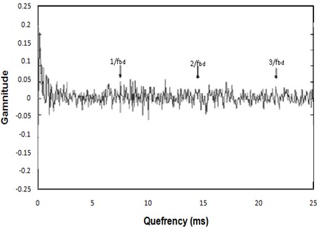
3.1.8. Cepstrum analysis
In the case of floating bush bearings afflicted with outer side defects, both axial and radial vibration cepstra reveal prominent peaks that correspond to the outer side defect frequency and its harmonics (as depicted in Figs. 18 and 19). These consistent cepstral patterns were observed across all the bearings tested for outer side defects. It is important to note that while the peaks related to the outer side defect frequency may not be the largest in amplitude, they do signify the periodicity of impulses within the vibration signal.
Fig. 18Axial vibration Cepstrum analysis for floating bush bearing with defects on outer side
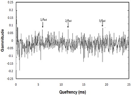
Fig. 19Radial vibration Cepstrum analysis for floating bush bearing with defects on outer side
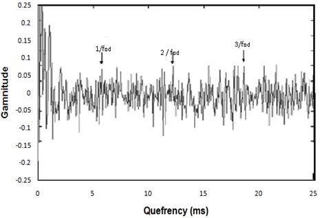
Conversely, for floating bush bearings with inner side defects, the axial vibration cepstrum demonstrates significant peaks corresponding to the inner side defect frequency and its harmonics (Fig. 20). However, the radial vibration cepstrum (Fig. 21) does not indicate peaks related to the floating bush defect frequency.
The data acquired indicates that cepstral peaks are only evident when the floating bush defect interacts with either the outer or inner side surface. For both outer and inner side defects, the axial vibration cepstra (Figs. 18 and 20) are more indicative of the defect compared to radial vibration. In the case of multi-point defects, whether on the outer or inner side (Fig. 21), the cepstrum does not offer indications of a defect. This phenomenon can be attributed to the vibration signal originating from impulses generated at various points within the defects. The relative positioning of these multi-point defects may either amplify or cancel out individual vibration signals, resulting in stronger or weaker overall vibration signals.
In conclusion, cepstrum analysis can be applied effectively only for diagnosing outer side defects in floating bush bearings. Moreover, it serves as a useful tool for indicating the repetition rate of impulses generated during the interaction with defects.
Fig. 20Axial vibration Cepstrum analysis for floating bush bearing with defects on inner side
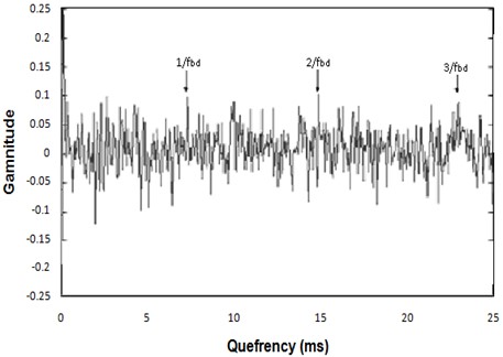
Fig. 21Radial vibration Cepstrum analysis for floating bush bearing with two defects on inner side
3.2. Frequency domain vibration analysis
3.2.1. Frequency characteristic
Figs. 22 to 24 display the vibration power spectra for a defect-free floating bush bearing at three different speeds. Several features can be observed from these spectra:
1) Notably, for the defect-free floating bush bearing, both the axial and radial vibrations exhibit differences at the same speed and under the same load.
2) Within the spectra, there are distinct major peaks that remain consistent across all three speeds of operation. In axial vibration, four significant peaks appear at approximately 231, 330, 680, and 900 Hz. In the case of radial vibration, two major peaks are noticeable at around 450 and 820 Hz. These frequency peaks do not vary with changes in speed, signifying their independence from the shaft's rotation speed. It's worth mentioning that these speed-independent peaks differ between axial and radial vibrations.
3) It’s observed that the overall vibration level for normal bearings increases with the rise in speed. This is a natural occurrence, as vibration tends to intensify with higher rotational speeds.
4) At all three speeds, the initial major peak in both axial and radial vibrations corresponds to the shaft's rotation frequency.
Fig. 22Vibration spectra for defect-free floating bush bearing [speed of 166 Hz]
![Vibration spectra for defect-free floating bush bearing [speed of 166 Hz]](https://static-01.extrica.com/articles/23699/23699-img22.jpg)
Fig. 23Vibration spectra for defect-free floating bush bearing [speed of 250 Hz]
![Vibration spectra for defect-free floating bush bearing [speed of 250 Hz]](https://static-01.extrica.com/articles/23699/23699-img23.jpg)
Fig. 24Vibration spectra for defect-free floating bush bearing [speed of 333 Hz]
![Vibration spectra for defect-free floating bush bearing [speed of 333 Hz]](https://static-01.extrica.com/articles/23699/23699-img24.jpg)
3.2.2. Peak ratio
The peak ratios in the enveloped spectra were calculated at two distinct defect frequencies: the outer side defect frequency () and the inner side defect frequency (). Notably, even in cases where a bearing had only an outer side defect, the peak ratios were also computed at the inner side defect frequency, and vice versa. The following observations were made:
1) The defect-free floating bush bearing (F0) exhibits higher peak ratios related to the inner side defect frequency () in comparison to those for the outer side defect frequency (). This observation is consistent in both the axial and radial vibration records.
2) For floating bush bearings afflicted with outer side defects (F1 to F4), the peak ratios for the outer side defect frequency increase with the size of the defect. This pattern is observed in both axial and radial vibration. Moreover, for these bearings (F1 to F4), it is noted that the peak ratios corresponding to the inner side defect frequency are lower than those for the defect-free bearing. Additionally, the peak ratios for continue to rise with the increasing size of the outer side defect, although they remain below the level of the defect-free bearing (F0). This is attributed to the fact that as the defect size increases, there is an overall increase in vibration, resulting in heightened amplitudes across all frequency components.
3) In bearings with outer side defects, the peak ratio values at the outer side defect frequency () surpass the peak ratios at the inner side defect frequency ().
4) For floating bush bearings with inner side defects (F5 to F8), the peak ratios for the inner side defect frequency do not exhibit a consistent increase with the size of the defect, whether in axial or radial vibration. In some instances, the peak ratios are even lower than those for a good bearing. For these bearings, the peak ratios corresponding to the outer side defect frequency display an upward trend as the size of the defect on the floating bush increases. Once again, this is due to the overall increase in vibration resulting from the growing defect size.
5) In bearings with inner side defects, the peak ratios at the inner side defect frequency () surpass the peak ratios at the outer side defect frequency ().
6) For the bearing with defects on both sides of the floating bush (F9), the axial and radial vibration data respectively indicate outer side defects only, even though both defects are present. Axial vibration yields higher peak ratios for , while radial vibration exhibits higher peak ratios for .
Table 2Peak ratio for axial and radial vibration with outer and inner side of bush defect
Test bearing | Axial vibration | Radial vibration | ||
PR at | PR at | PR at | PR at | |
F0 | 20.4 | 28.3 | 12.8 | 26.8 |
F1 | 36.6 | 13.3 | 16.8 | 17.1 |
F2 | 27.8 | 18.3 | 19.7 | 18.4 |
F3 | 42.5 | 20.4 | 27.2 | 22.8 |
F4 | 50.0 | 22.3 | 59.2 | 11.3 |
F5 | 8.2 | 15.9 | 3.8 | 17.9 |
F6 | 12.8 | 33.0 | 7.4 | 25.9 |
F7 | 26.3 | 27.5 | 18.7 | 10.3 |
F8 | 28.1 | 22.1 | 29.5 | 41 |
F9 | 17.6 | 10.3 | 11.7 | 19.8 |
The effectiveness of various time and frequency domain parameters has been assessed for diagnosing localized defects in floating bush bearings [20-24]. Table 3 presents a comparative evaluation of the performance of these parameters in defect diagnosis. The detectability of defects using these parameters is categorized as “Good (5), Fair (3), or Poor (1)” based on their effectiveness in diagnosing issues with floating bush bearings, as outlined in Section 3. Specifically, for inner or outer side defects, if a parameter clearly indicates the presence of a defect, it is rated as “Good”. If the defect is indicated in some instances but not consistently, it is rated as “Fair”. If the parameter does not indicate the defect at all, it is rated as “Poor”.
Table 3 reveals that in the time-domain analysis, parameters such as waveform, form factor, parameter , and cepstrum are effective indicators for identifying outer side defects in floating bush bearings. On the other hand, kurtosis, crest factor, and skewness are good for detecting inner side defects. When it comes to diagnosing combined defects, parameters like peak to valley, crest factor, skewness, and kurtosis demonstrate effectiveness.
Table 3Comparison of defect detectability of time and frequency domain parameters
Defects | Outer race | Inner race | Combined | Parameter effectiveness factor | ||
Bearing | F1-F3 | F4 | F5-F7 | F8 | F9 | |
Parameter | Single point | Multi point | Single point | Multi point | Multi point | |
Peak to valley | 3 | 3 | 3 | 3 | 5 | 3.40 |
Waveform | 5 | 5 | 3 | 3 | 3 | 3.80 |
RMS Level | 3 | 3 | 3 | 5 | 1 | 3.00 |
Crest factor | 1 | 1 | 5 | 1 | 5 | 2.60 |
Form factor | 5 | 5 | 1 | 5 | 1 | 3.40 |
Skewness | 3 | 1 | 5 | 1 | 5 | 3.00 |
Kurtosis | 1 | 1 | 5 | 5 | 5 | 3.40 |
Parameter K | 5 | 5 | 3 | 5 | 3 | 4.20 |
Ceptrum | 5 | 5 | 1 | 1 | 3 | 3.00 |
Peak Ratio | 5 | 5 | 3 | 3 | 1 | 3.40 |
4. Conclusions
In the assessment of time and frequency domain parameters for diagnosing localized defects in floating bush bearings, significant findings have emerged:
1) In the time-domain analysis, key parameters such as parameter (Effectiveness = 4.2), waveform (Effectiveness = 3.8), form factor (Effectiveness = 3.4), and cepstrum excel in pinpointing outer side defects, while kurtosis (Effectiveness = 3.4), crest factor, and skewness prove effective for identifying inner side faults.
2) Prove effective for identifying inner side faults.
3) For diagnosing combined defects, a combination of parameters, including peak to valley, crest factor, skewness, and kurtosis, demonstrates exceptional utility in providing comprehensive insights into multifaceted issues.
4) In the frequency domain, the enveloped spectrum emerges as a robust method for overall defect detection, while peak ratio is particularly adept at revealing outer side faults. It’s noteworthy that the waveform parameter showcases the highest efficacy, offering a versatile tool for identifying both inner and outer defects.
These research outcomes provide invaluable guidance for diagnosing defects in floating bush bearings by harnessing the capabilities of various time and frequency domain parameters. This holistic approach empowers maintenance and engineering teams to make informed decisions, ensuring the optimal performance and longevity of these critical components.
References
-
N. Tandon and A. Choudhury, “A review of vibration and acoustic measurement methods for the detection of defects in rolling element bearings,” Tribology International, Vol. 32, No. 8, pp. 469–480, Aug. 1999, https://doi.org/10.1016/s0301-679x(99)00077-8
-
Kim et al., “A review of rolling element bearing health monitoring,” in Proceedings of Machinery Vibration Monitoring and Analysis Meeting, 1983.
-
J. Mathew and R. J. Alfredson, “The condition monitoring of rolling element bearings using vibration analysis,” Journal of Vibration and Acoustics, Vol. 106, No. 3, pp. 447–453, Jul. 1984, https://doi.org/10.1115/1.3269216
-
P. D. Mcfadden and J. D. Smith, “Vibration monitoring of rolling element bearings by the high-frequency resonance technique – a review,” Tribology International, Vol. 17, No. 1, pp. 3–10, Feb. 1984, https://doi.org/10.1016/0301-679x(84)90076-8
-
P. Y. Kim, “A review of rolling element bearing health monitoring (II): preliminary test results on current technologies,” in Proceedings of Machinery Vibration Monitoring and Analysis Meeting, 1984.
-
P. Y. Kim, “A review of rolling element bearing health monitoring (III): preliminary test results on eddy current proximity transducer technique,” in 3rd International Conference on Vibration in Rotating Machinery, 1984, https://doi.org/10.1177/0957456520948279
-
B. Dolenc, P. Boškoski, and Juričić, “Distributed bearing fault diagnosis based on vibration analysis,” Mechanical Systems and Signal Processing, Vol. 66-67, pp. 521–532, Jan. 2016, https://doi.org/10.1016/j.ymssp.2015.06.007
-
M. Farajzadeh-Zanjani, R. Razavi-Far, and M. Saif, “Dimensionality reduction-based diagnosis of bearing defects in induction motors,” in IEEE International Conference on Systems, Man and Cybernetics (SMC), Oct. 2017, https://doi.org/10.1109/smc.2017.8123006
-
M. Farajzadeh-Zanjani, R. Razavi-Far, M. Saif, and L. Rueda, “Efficient feature extraction of vibration signals for diagnosing bearing defects in induction motors,” in International Joint Conference on Neural Networks (IJCNN), Jul. 2016, https://doi.org/10.1109/ijcnn.2016.7727789
-
M. Farajzadeh-Zanjani, R. Razavi-Far, M. Saif, J. Zarei, and V. Palade, “Diagnosis of bearing defects in induction motors by fuzzy: neighborhood density-based clustering,” in IEEE 14th International Conference on Machine Learning and Applications (ICMLA), pp. 935–940, Dec. 2015, https://doi.org/10.1109/icmla.2015.114
-
J. Sopanen and A. Mikkola, “Dynamic model of a deep-groove ball bearing including localized and distributed defects. Part 2: Implementation and results,” Proceedings of the Institution of Mechanical Engineers, Part K: Journal of Multi-body Dynamics, Vol. 217, No. 3, pp. 213–223, Sep. 2003, https://doi.org/10.1243/14644190360713560
-
J. Sopanen and A. Mikkola, “Dynamic model of a deep-groove ball bearing including localized and distributed defects. Part 1: Theory,” Proceedings of the Institution of Mechanical Engineers, Part K: Journal of Multi-body Dynamics, Vol. 217, No. 3, pp. 201–211, Sep. 2003, https://doi.org/10.1243/14644190360713551
-
H. R. Martin and F. Honarvar, “Application of statistical moments to bearing failure detection,” Applied Acoustics, Vol. 44, No. 1, pp. 67–77, Jan. 1995, https://doi.org/10.1016/0003-682x(94)p4420-b
-
K. F. Martin and P. Thorpe, “Normalised spectra in monitoring of rolling bearing elements,” Wear, Vol. 159, No. 2, pp. 153–160, Dec. 1992, https://doi.org/10.1016/0043-1648(92)90298-m
-
A. Sturm and D.-L. D. Kinsky, “Diagnostics of rolling-element bearing condition by means of vibration monitoring under operating conditions,” Measurement, Vol. 2, No. 2, pp. 58–62, Apr. 1984, https://doi.org/10.1016/0263-2241(84)90033-2
-
G. Krishnappa, “Machinery condition monitoring,” in Encyclopedia of Acoustics, Wiley, 1997, pp. 869–879, https://doi.org/10.1002/9780470172520.ch73
-
D. Dyer and R. M. Stewart, “Detection of rolling element bearing damage by statistical vibration analysis,” Journal of Mechanical Design, Vol. 100, No. 2, pp. 229–235, Apr. 1978, https://doi.org/10.1115/1.3453905
-
J. Shiroishi, Y. Li, S. Liang, T. Kurfess, and S. Danyluk, “Bearing condition diagnostics via vibration and acoustic emission measurements,” Mechanical Systems and Signal Processing, Vol. 11, No. 5, pp. 693–705, Sep. 1997, https://doi.org/10.1006/mssp.1997.0113
-
Li et al., Encyclopedia of Vibration: Bearing Diagnostics. Academic Press London, 2023.
-
D. L. Carter, “Some instrumentation considerations in rolling bearing condition analysis,” 2002.
-
D. E. Newland, “Wavelet analysis of vibration: part 1-theory,” Journal of Vibration and Acoustics, Vol. 116, No. 4, pp. 409–416, Oct. 1994, https://doi.org/10.1115/1.2930443
-
D. E. Newland, “Wavelet Analysis of Vibration: Part 2-Wavelet Maps,” Journal of Vibration and Acoustics, Vol. 116, No. 4, pp. 417–425, Oct. 1994, https://doi.org/10.1115/1.2930444
-
R. Rubini and U. Meneghetti, “Application of the envelope and wavelet transform analyses for the diagnosis of incipient faults in ball bearings,” Mechanical Systems and Signal Processing, Vol. 15, No. 2, pp. 287–302, Mar. 2001, https://doi.org/10.1006/mssp.2000.1330
-
P. W. Tse, Y. H. Peng, and R. Yam, “Wavelet analysis and envelope detection for rolling element bearing fault diagnosis-their effectiveness and flexibilities,” Journal of Vibration and Acoustics, Vol. 123, No. 3, pp. 303–310, Jul. 2001, https://doi.org/10.1115/1.1379745
About this article

The authors have not disclosed any funding.
The datasets generated during and/or analyzed during the current study are available from the corresponding author on reasonable request.
All the authors are equally contributed for work.
The authors declare that they have no conflict of interest.
