Abstract
The temperature at which the carbon brushes and the structure of the rings in the electric propulsion slip ring operate has a crucial influence on the safe and reliable operation of the ship. In order to control the temperature of the local structure of the electric propulsion slip ring, this study established a carbon brush and ring piece model through finite element simulation analysis and designed a five-factor, four-level orthogonal test to derive the sensitivity of the final temperature influence factor: initial temperature > current > wind speed > pressure > speed; the optimal combination of parameters is obtained: initial temperature 35 °C, pressure 25 N, speed 5 rpm, wind speed 0.20 m/s, and current 40 A, and the optimal parameters are substituted for the temperature field simulation. The results show that the relatively large area of temperature is distributed on the carbon brushes with a maximum value of 58.3 °C, which is relatively reasonable in size and distribution; the relatively large area of potential is distributed on the carbon brushes, the maximum value of which is 0.3V The entire potential distribution is symmetrical, indicating a reasonable current path; the relatively large area of current density distribution is on the carbon brushes with a value of 64.7 A/cm2, the entire current density distribution is symmetrical and corresponds to the potential distribution, which, together with the frictional rotation, corresponds to the temperature distribution, indicating that the simulation results have a certain degree of reliability.
1. Introduction
The slip ring of 10 MW electric propulsion consists of main power slip ring, signal slip ring, fluid slip ring and other structures. Among them, the most concerned key part is the temperature of the carbon brush and the ring in the main power slip ring, which provides the maximum guarantee for the overall operation in the complex marine environment [1]. Its internal structure is similar to the conductive slip ring. It is a precision transmission device that realizes the signal and current transmission of two relative rotating mechanisms [2]. It can be used in almost all industries such as aviation and navigation [3]. In today’s industrial background, the reliability and transmission of the conductive slip ring determine the success or failure of the entire aerospace system [4]. Therefore, it is necessary to control the temperature of the internal rotation of the slip ring, which will help to improve its signal transmission quality and reduce the amount of wear [5], [6]. Therefore, it is of great practical significance to study the reliability of the conductive slip ring.
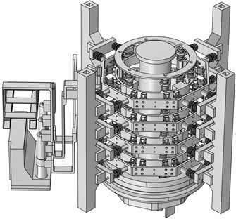
In order to improve the contact quality and service life of the brush wire, many scholars have focused on controlling the brush wire contact deviation, brush wire assembly and friction heat [7-9]. Sun Yuanhang et al. quantized the influence of thermo-electric multi-field coupling on the overall slip ring, and predicted the life of the friction pair [10]; wang Yueze et al. used the finite element analysis method to quantitatively analyze the SINS angle error caused by temperature excitation through numerical simulation and verified it. The model is verified by comparing the numerical and experimental results [11]; Yu Zhongquan et al. determined the temperature gradient of each unit point in the optical fiber ring by finite element analysis, and analyzed the temperature performance of the optical fiber ring [12]; Dong Yongqian et al. designed the orthogonal test scheme of SiC plate, and summarized the process of simulating thermal deformation [13]. Guo Y. et al. used the coupling method of multiple physical fields to obtain the cooling parameters of the needle valve body to ensure that the maximum temperature is lower than 610.8 K, and the material can still maintain high strength [14]; Ariyo D. O. et al. carried out subcooled flow boiling by using the non-equilibrium boiling model of computational fluid dynamics (CFD, ANSYS ), and finally demonstrated the ability of the model to accurately predict the subcooled boiling flow in microchannels [15]. So far, there are few simulation studies on the temperature field of slip ring carbon brush and ring model of electric propulsion. In order to control the temperature of the electric propulsion slip ring carbon brush and the ring structure, this study analyzes the sensitivity of each influencing factor by designing an orthogonal test, and summarizes the optimal parameter combination. Finally, the optimal parameters are used for simulation verification. Based on the above analysis, the simulation has an accurate guiding analysis for the slip ring in the real working state. The three-dimensional model is shown in Fig. 1.
Fig. 1Three-dimensional model of the whole slip ring
2. Building simulation model
The key parts of the electric propulsion slip ring are carbon brushes and ring plates, and there are many pairs of carbon brushes on the ring plates. However, in order to save time and improve the computational efficiency, only one ring and a pair of carbon brushes are selected for simulation. The three-dimensional model is modeled according to the actual structure, and the model is processed in detail. The whole model is placed horizontally, with a ring height of 100 mm, a radius of 400 mm and a thickness of 20 mm. The carbon brush is 30 mm high, 50 mm long and 35 mm wide, and its structure is shown in Figs. 2 and 3.
Fig. 2Schematic diagram of Carbon brush and ring structure model: 1 – ring structure; 2 – carbon brush
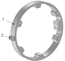
Fig. 3Schematic diagram of carbon brush structure model
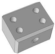
Fig. 2 is composed of carbon brush and ring structure. The overall model is placed horizontally, and the carbon brush is at the fixed end and in contact with the side of the ring sheet to form a friction pair. When working, the ring rotates, the carbon brush stays still, the carbon brush and the ring contact and rub with each other, and the current is transmitted from the fixed end to the transmission end to realize the function of signal transmission and non-twisting.
The model is meshed by a more refined free tetrahedral mesh. The complete mesh contains 281433 domain elements, 38942 boundary elements and 3249 edge elements, as shown in Fig. 4.
Fig. 4Schematic diagram of carbon brush and ring mesh generation

Before the beginning of the simulation, the carbon brush and ring model are established. According to the actual material (carbon brush and ring), the Copper material is endowed with carbon brush and ring model to form the assembly. During the rotation of the carbon brush and the ring, the actual model rotates at the inner end of the ring, and the speed of the ring is given. The contact area of the carbon brush is 0.001982 square meters around the clockwise direction. Fig. 4 is the direction of the carbon brush and the ring model, and the outside is set to forced convection. Set a certain wind speed. The steady-state analysis of the model is carried out and the ambient temperature is given.
3. Simulation analysis and result discussion
3.1. Design orthogonal test
In this study, the orthogonal experiment with 5 factors and 4 levels is selected. Among the main factors affecting the final temperature, initial temperature, pressure, rotational speed, wind speed and current are selected as orthogonal test factors, which are recorded as A, B, C, D and E respectively. The orthogonal test scheme of 5 factors and 4 levels is designed, and the simulation parameters are reasonably optimized. The factor level is shown in Table 1.
Table 1Orthogonal experiment table
Level | Test parameters | ||||
A | B | C | D | E | |
Initial temperature / °C | Pressure / N | Rotational speed / rpm | Wind speed / m/s | Current / A | |
1 | 35 | 10 | 2 | 0.05 | 40 |
2 | 40 | 15 | 3 | 0.10 | 50 |
3 | 45 | 20 | 4 | 0.15 | 60 |
4 | 50 | 25 | 5 | 0.20 | 70 |
3.2. Orthogonal test results and analysis
The final temperature results of 16 groups of tests were statistically analyzed, and the average and range values of the sum of different levels of each index were calculated. The optimal level factors are selected for matching, and the best combination of simulation parameters is given. The sensitivity of each influencing factor is sorted by range analysis. Table 2 is the analysis table of test results.
Table 2Analysis table of test results
Test project | Test parameters | Final temperature / °C | ||||
A | B | C | D | E | ||
Initial temperature / °C | Pressure / N | Rotational speed / rpm | Wind speed / m/s | Current / A | ||
1 | 1 | 1 | 1 | 1 | 1 | 51.7 |
2 | 1 | 2 | 2 | 2 | 2 | 49.5 |
3 | 1 | 3 | 3 | 3 | 3 | 49.4 |
4 | 1 | 4 | 4 | 4 | 4 | 49.9 |
5 | 2 | 1 | 2 | 3 | 4 | 67.3 |
6 | 2 | 2 | 1 | 4 | 3 | 55.0 |
7 | 2 | 3 | 4 | 1 | 2 | 57.0 |
8 | 2 | 4 | 3 | 2 | 1 | 48.0 |
9 | 3 | 1 | 3 | 4 | 2 | 57.5 |
10 | 3 | 2 | 4 | 3 | 1 | 52.6 |
11 | 3 | 3 | 1 | 2 | 4 | 69.8 |
12 | 3 | 4 | 2 | 1 | 3 | 68.7 |
13 | 4 | 1 | 4 | 2 | 3 | 73.0 |
14 | 4 | 2 | 3 | 1 | 4 | 86.1 |
15 | 4 | 3 | 2 | 4 | 1 | 56.4 |
16 | 4 | 4 | 1 | 3 | 2 | 60.3 |
K1 | 200.4 | 249.6 | 236.8 | 263.6 | 208.8 | The order of the final temperature influence factors is primary and secondary: A > E > D > B > C Optimal combination: A1B4 C4D4E1 |
K2 | 227.2 | 243.2 | 242.0 | 240.4 | 224.0 | |
K3 | 248.4 | 232.4 | 241.2 | 229.6 | 246.0 | |
K4 | 275.6 | 226.8 | 232.4 | 218.8 | 273.2 | |
k1 | 50.1 | 62.4 | 59.2 | 65.9 | 52.2 | |
k2 | 56.8 | 60.8 | 60.5 | 60.1 | 56.0 | |
k3 | 62.1 | 58.1 | 60.3 | 57.4 | 61.5 | |
k4 | 68.9 | 56.7 | 58.1 | 54.7 | 68.3 | |
R | 18.8 | 5.6 | 2.4 | 11.2 | 16.1 | |
Optima | A1 | B4 | C4 | D4 | E1 | |
Since the test index is the final temperature, and kA4 > kA3 > kA2 > kA1, it can be determined that A1 is the optimal level of factor A; similarly, B4, C4, D4 and E1 can be calculated and determined as the optimal levels of B, C, D and E factors, respectively. Then the optimal level combination A1B4C4D4E1 of the five factors is the optimal level combination of this experiment. Comparing the range R value, it can be seen that RA > RE > RD > RB > RC, so the sensitivity order of each influencing factor is A > E > D > B > C.
Fig. 5Final temperature main effect diagram
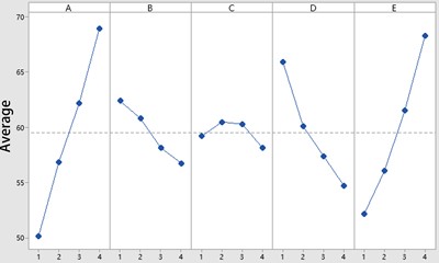
In order to intuitively analyze the change rule of the final temperature of the local slip ring under different levels of initial temperature, pressure, speed, wind speed and current, the main effect diagram of the mean value of the five factors (initial temperature, pressure, speed, wind speed and current) on the final temperature is drawn as shown in Fig. 5.
It can be seen from the main effect diagram of the final temperature mean that as the numerical levels of factors A (initial temperature) and E (current) increase, the mean line of the final temperature of the local slip ring basically shows an upward trend, and there is a main effect, and the steepness of the line represents the main effect value of the factor. With the increase of the numerical level of factor B, factor C and factor D, the mean broken line of the final temperature of the local slip ring basically shows a downward trend, and there is also a main effect, and the steepness of the broken line represents the main effect of the factor. It can be found that the main effect of factor A (initial temperature) is the most significant, followed by factor E, factor D and factor B; it can also be found that the mean values of A1, B4, C4, D4 and E1 are the smallest, which further proves that the optimal combination of the test scheme is: initial temperature 35 °C, pressure 25 N, speed 5 rpm, wind speed 0.20 m/s and current 40 A.
4. Simulated test
The above optimized parameter conditions (initial temperature 35 °C, pressure 25 N, speed 5 rpm, wind speed 0.20 m/s and current 40 A) are used for simulation verification. The simulation results are as follows.
Fig. 6Carbon brush and ring temperature
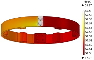
Fig. 7Carbon brush and ring potential distribution
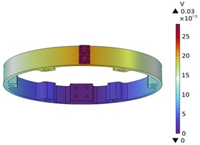
Fig. 6 is the temperature distribution cloud diagram of carbon brush and ring sheet. From the diagram, it can be seen that the relatively large temperature area of carbon brush and ring sheet is distributed on the carbon brush. Because the simulation is a single group of carbon brush and ring sheet, it is not affected by other factors, so the maximum temperature is 58.3 °C, and the temperature size and distribution are relatively reasonable.
Fig. 7 shows the potential distribution cloud diagram of the carbon brush and the ring. It can be seen from the figure that the relatively large area of the carbon brush and the ring potential is distributed on the carbon brush, and the maximum value is 0.3 V. It can be seen that the electric potential flows from the four holes of the carbon brush, then shunts on the loop, and finally flows out from the protruding side of the inner loop. The whole electric potential distribution is symmetrical, indicating that the current direction is reasonable.
Fig. 8Carbon brush and ring current density distribution cloud diagram
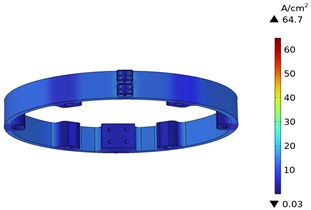
Fig. 8 shows the current density distribution of carbon brush and ring. It can be seen from the figure that the current density distribution of carbon brush and ring is relatively large, and the corresponding current density is also high, which is 64.7 A/cm2. The whole current density distribution is symmetrical, corresponding to the potential distribution, coupled with the friction rotation, corresponding to the temperature distribution, indicating that the simulation results have certain reliability.
5. Conclusions
By designing the orthogonal test of five factors and four levels, the sensitivity of the final temperature influence factor is obtained: initial temperature > current > wind speed > pressure > speed; the optimal combination parameters are obtained: initial temperature 35 °C, pressure 25 N, speed 5 rpm, wind speed 0.20 m/s and current 40 A, and the optimal parameters are substituted into the temperature field simulation. The results show that the temperature is relatively large. The area is distributed on the carbon brush, and its maximum value is 58.3 °C, and its size and distribution are relatively reasonable. The relatively large area of the potential is distributed on the carbon brush, and the maximum value is 0.3 V. The whole potential distribution is symmetrical, indicating that the current trend is reasonable. The relatively large area of current density distribution is distributed on the carbon brush, and its value is 64.7 A/cm2. The whole current density distribution is symmetrical, which corresponds to the potential distribution. Coupled with friction rotation, it corresponds to the temperature distribution, indicating that the simulation results have certain reliability.
References
-
T. Xie, “Analysis on the importance of mixed dielectric slip ring in electric propulsion pod thruster,” (in Chinese), Journal of Shandong Industrial Technology, Vol. 8, No. 268, pp. 29–29, 2019.
-
J. Lu, L. Xing, and Y. Li, “The key technology and developing trend of the precision conductive slip-ring,” (in Chinese), Navigation and Control, Vol. 14, No. 1, pp. 20–26, 2015.
-
W. Li, H. Fu, and F. Zhang, “A long-life conductive slip ring for centroid leveling,” (in Chinese), Technology Innovation and Application, Vol. 302, No. 10, pp. 92–93, 2020.
-
J. Yu, Y. Sun, and Y. Wang, “Process optimization method of aerospace conductive slip ring based on transmission stability and reliability,” (in Chinese), Navigation and Control, Vol. 20, No. 4, pp. 87–95, 2021.
-
C. Li, C. Li, and T. Zhang, “Study on the factors affecting wear life of the slip ring of LEO satellite,” (in Chinese), Aerospace Shanghai, Vol. 36, No. S2, pp. 79–83, 2019.
-
L. Liu, Y. Zhu, and H. Liu, “Study on transmission reliability of long life space electric slip ring,” (in Chinese), Optics and Precision Engineering, Vol. 27, No. 9, pp. 2028–2035, 2019.
-
X. Chen, Y. Wang, and Y. Sheng, “Vision-aided brush alignment assembly system for precision conductive slip rings,” Machines, Vol. 10, No. 5, pp. 393–393, 2022.
-
S. Li, Y. Ma, and S. Zhang, “Numerical and experimental investigation on heat transfer characteristics of flexible bristle brush seal,” (in Chinese), Mechanical and Electrical Engineering Magazine, Vol. 38, No. 2, pp. 133–141, 2021.
-
J. Yan, M. Liu, and X. Song, “Numerical study on heat transfer characteristics of brush seal,” (in Chinese), Mechanical and Electrical Engineering Magazine, Vol. 38, No. 10, pp. 1230–1237, 2021.
-
Y. Sun, Y. Wang, and X. Sun, “Research on failure modeling and process optimization of transmission conductive slip ring for aerospace,” (in Chinese), Journal of Mechanical Engineering, Vol. 56, No. 16, pp. 1–2, 2020.
-
Y. Wang, L. Ma, and H. Yu, “Modeling and simulation on temperature performance in fiber optic gyroscope fiber coil of shipborne strapdown inertial navigation system,” Tianjin Navigation Instrument Research Institute, 2016.
-
Y. Sun, Y. Wang, and X. Sun, “Simulation analysis of temperature characteristic of fiber coil,” (in Chinese), Journal of Applied Optics, Vol. 33, No. 2, pp. 421–426, 2012.
-
Y. Dong, H. Ma, and W. Li, “SiC thermal deformation simulation based on orthogonal experiment,” (in Chinese), Electronics Process Technology, Vol. 43, No. 6, pp. 330–333, 2022.
-
Y. Guo, K. Li, and Y. Li, “Analysis of conjugate heat transfer characteristics of nozzle in middle-high speed marine diesel engine,” International Journal of Hydromechatronics, Vol. 5, No. 2, pp. 124–135, 2022.
-
Y. Guo, K. Li, and Y. Li, “Critical heat fluxes for subcooled flow boiling in optimised microchannels,” International Journal of Hydromechatronics, Vol. 3, No. 2, pp. 140–154, 2022.
About this article

The authors have not disclosed any funding.
The datasets generated during and/or analyzed during the current study are available from the corresponding author on reasonable request.
The authors declare that they have no conflict of interest.
