Abstract
The material structure of 3D-models printed via the fused deposition modelling (FDM) technique is mainly affected in the z-direction of the 3D-print as a result of the layer-by-layer approach which tend to exhibit a deformation behavior corresponding to a type of transversely orthotropic material. Moreover, uncontrolled parameters such as printing temperature and printing speed have been reported to adversely affect 3D-print quality leading to undesired effects such as distortion and warpage. The additive manufacturing process is a relatively new field in advanced manufacturing where further research and innovation are required to overcome the limited strength and structural performance observed in presently 3D-printed components. In line with the above, this study proposes the numerical investigation of the warping behavior in PLA (Polylactic acid) - based 3D printed models by considering the finite element method (FEM) software of LS-DYNA. The warping investigation was specifically centered on the cooling cycle prevailing between the layer-by-layer structures. The findings of this study showed that warpage would most likely occur in the thermal process model corresponding to abrupt change in temperature due to a buildup of strain between the bottom most layers of the 3D model and the build plate. The findings of this study, which shed light on the warping behaviour in 3D-models, has direct implications on the final quality of 3D-printed components.
1. Introduction
The 3D-printing technology is re-shaping the manufacturing industries in various fields ranging from culinary to medical science by incorporating the unconventional additive-manufacturing approach [1]. This new manufacturing technology is versatile enabling the creation of complex structures and bespoke designs by considering a wide variety of materials ranging from polymeric-based to metallic materials [2, 3]. The additive manufacturing process is generally conducted in a systematic approach whereby materials are deposited, joined or solidified under specific conditions in a computer controlled environment [4]. The fused deposition modelling (FDM) technique, which is generally considered as one of the most common 3D printed technique for quick prototyping, operates by depositing melted filament material in a pre-determined path via a layer-by-layer approach [4]. Besides their numerous advantages in terms of rapid prototyping, improved accuracy and material waste reduction, the full commercialization of 3D-printing technology is restricted by material limitations and high production costs among other factors [5].
Given the print mechanism of FDM technique, the material structure of 3D-printed models, which is mainly affected in the -direction of the 3D-print as a result of the layer-by-layer approach, tend to exhibit a deformation behavior corresponding to a type of transversely orthotropic material. The fracture mechanisms in 3D-printed parts tend to be thus governed by their specific material structure, which is predominantly accentuated by the weak interlaminar strength prevailing between the fused deposited layers. The interlaminar region prevailing between the fused deposited layers, which falls on the weakest plane orthogonal to the vertical axis of print, has been reported to be prone to crack development [6-8]. Other issues associated with print defects, which are frequently encountered in fused deposition modelling, namely warping, infill overlap, layer misalignment, over- and under-extrusion, are assumed to further contribute to the propensity of 3D-printed parts to fracture. Moreover, warping, which is generally encountered in the post-processing phase and characterized by build-up of residual internal stresses due to uncontrolled and rapid cooling, greatly affects the final quality of 3D-printed parts.
The FEM approach was selected for this investigation as it enabled the possibility to suppress other aspects of the material structure not explored in this study, such as the intrinsic print defects. From literature, previous studies have been conducted to predict the residual stresses developed in 3D printed parts due to warping by considering numerical simulation method [9,10]. Warping was investigated as it is thought to cause major disruptions to 3D printing operation such as irreversible distortional damage between 3D-printed part and the build platform especially due to insufficient adhesion strength to overcome the induced forces from thermal stress [9]. In another study, a free-form deformation (FFD) approach was adopted to compensate for deformations frequently observed in the 3D printing process such as warpage [11]. Moreover, modification was brought to the pre-processing stage in another study by adopting a new slicing method known as brinking to reduce the warping phenomenon [12]. From experimental and numerical simulation results, the integration of a brim section at the base layer was found to greatly reduce the stresses build-up leading to warpage [10].
From the above findings, further research and innovation are required to overcome the limited strength and structural performance observed in 3D-printed components manufactured via AM. To address the limited strength observed in 3D-printed parts, the aim of this study is to investigate via numerical modelling one of the major issues observed in the post-processing phase of AM about warping. The various causes linked to this phenomenon will be explored via the numerical investigation of warping in PLA (Polylactic acid) -based 3D printed models by considering the finite element method (FEM) software of LS-DYNA. As a first step to investigate the warping phenomenon in 3D-Printed parts, the proposed study was predominantly focused on investigating the conduction of heat prevailing between the first deposited layer and that of the build plate interface. The findings of this study is expected to shed light on the principle factor of warping and its underlying mechanisms which has direct implications on the durability-strength performance of 3D-printed components.
2. Materials and methods
2.1. Material parameters
In this study, a specific type of filament material was considered for further investigation which consists of a composite base and can be further reinforced with a continuous fiber reinforcement (CFR) component such as carbon fiber, kevlar, and fiberglass. The material data was thus selected from a specific type of filament known as Onyx which are produced by Markforged Inc., Watertown, Massachusetts, United States. The Onyx filament, which can be further reinforced with any continuous fiber, is a micro carbon fiber filled nylon which was reported to have a stiffness and strength 1.4 times of that of ABS.
From previous studies, 3D-printed parts were found to demonstrate orthotropic characteristics given their print orientation, material characteristics and printing environment [6, 9, 11]. Given the layer-by-layer material structure of 3D-printed specimens, a specific case of orthotropic material model was considered. Therefore, a vertical transversely isotropic material model as outlined by Eq. (1) below was selected [13, 14]:
The corresponding engineering constants of compliance matrix () in Eq. (2) in terms of the elastic moduli:
Poisson’s ratios and shear moduli for the vertical transversely isotropic material model is given in Table 1.
Based on literature information, a mean orthotropic characteristic in terms of longitudinal to transverse stiffness ratio of 100:90 was selected. The detailed orthotropic characteristics of Onxy filament based on the : ratio of 100:90 is given in Table 1.
Table 1Orthotropic material parameters for filament material.
Material model | Orthotropic material parameters | ||||
Elastic modulus (MPa) | Poisson’s ratio | Shear modulus (MPa) | |||
Onyx Filament | 3000 | 2700 | 0.27 | 0.27 | 1106 |
The orthotropic properties displayed in Table 1 correlated to a large extent with the ones devised for the investigation of 3D-printed polymeric parts [15].
2.2. Coefficient of thermal expansion for filament material
In accordance with the orthotropic nature of the composite-based filament material, the coefficient of thermal expansion for the Onyx filament was also found to vary with respect to the three principal axes as reported in a previous study [16]. The major reason leading to variations in the coefficients of thermal expansion specifically in the cross-flow and orthogonal directions corresponding to the direction of print and vertical -direction respectively, was attributed to the print orientation [16]. Similar coefficients of thermal expansion for the filament material derived from previous research was employed in this study as displayed in Table 2.
A ratio of coefficient of thermal expansion of 100:40 corresponding to the vertical -direction with respect to the direction of print was maintained throughout the investigation. This anisotropy was however observed to be lower in filament materials having a lower filler content. The coefficients of thermal expansion for the Onyx filament, which will be considered in the orthotropic thermal material model in the numerical model, are displayed in Table 2. The expansion and subsequent warping behaviour of the 3D print following the printing and cooling stages respectively, was simulated by considering a positive coefficient of thermal expansion as shown in Table 2.
Table 2Coefficient of thermal expansion for filament material [16]
Material direction | : | |||
Radial | Tangential | Longitudinal | ||
Coefficient of thermal expansion (K-1) | 24.8×10⁻⁵ | 24.8×10⁻⁵ | 9.5×10⁻⁵ | 100:40 |
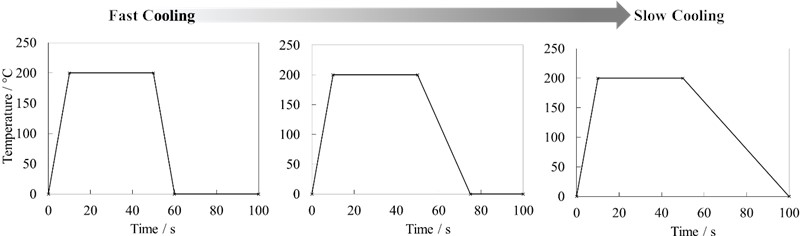
To investigate the effects of printing temperature and cooling rate on the warping behaviour of 3D-prints, three cycles of heating-cooling for the 3D-printing process were considered. As displayed in Fig. 1, the duration of the cooling phase of the 3D-printing process was varied following the printing stage. As per the heating-cooling cycles considered during the simulation of the 3D-printing process, identical periods for soaking temperature was considered in all three cases as indicated by the plateau region displayed in Fig. 1. Besides, in this study, the speed of printing was assumed to be fast enough such that the cooling rate in the first few deposited layers would be approximately the same.
Fig. 1Three heating-cooling cycles considered for simulation of 3D-printing process
2.3. Geometrical model, boundary conditions and meshed model
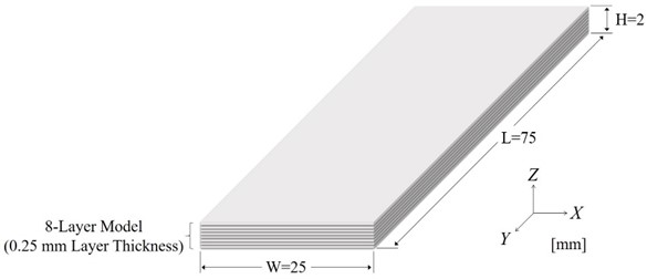
The 3D-printed model shown in Fig. 2, was designed as an 8-layer model each having a print-layer thickness of 0.25 mm. The model which had overall dimensions of 2 mm in height, 75 mm in length and 25 mm in width, was designed on the finite element modelling and post processing (FEMAP) software (Siemens Digital Industries Software, Plano, TX, USA). Other variable conditions and printing parameters were kept constant and the effect of printing path on the warping behavior for instance was minimized by considering a 3D-printed specimen with reduced thickness, length and width. The bottom-horizontal section of the model was constrained in all directions to simulate the build plate section. The meshed model as shown in Fig. 3 was discretized into 44880 nodes and 38400 elements in FEMAP software by considering hexahedral mesh solids.
The simulation of warping behaviour in filament-based 3D prints was conducted on LS-DYNA (Livermore Software Technology, Livermore, CA, USA) by considering the orthotropic thermal material setting. The utilization of FEM software to investigate material behavior in the field of additive manufacturing provide numerous benefits namely by controlling and overcoming frequent defects encountered in 3D prints such as voids, over extrusion and layer separation. The effective strain criterion, which has been widely used to investigate failure mechanisms in various material types [17, 18], was considered to assess the material deformation in the 3D-printed model.
Fig. 2Dimensions of final geometrical model
3. Results and discussion
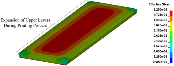
As shown in Fig. 4, the fringe plots of effective strain distribution obtained from the three thermal process models were compared to assess the warping behavior. At maximum printing temperature, all models exhibited an expansion in terms of volumetric change as displayed in Fig. 5. A displacement scale factor of 5 was applied to emphasize the changes due to thermal expansion.
Fig. 3Geometrical model discretized into 44880 nodes and 38400 elements in FEMAP software
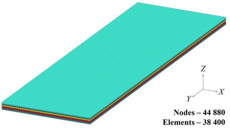
Fig. 4Fringe plots of effective strain distribution obtained from the three thermal process models
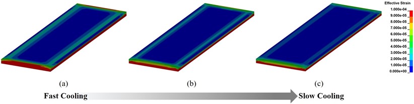
The thermal expansion in the model was brought to an end at 50 s as revealed by the simulation results in accordance with the printing-cooling cycle displayed in Fig. 1. At the end of the printing phase, the subsequent cooling cycle would lead to a contracting phase that would reduce the expansion in the model and return to its initial state at room temperature. This could be evidenced from the outline of the fringe plots in Fig. 4 which corresponded to the final and undeformed state of simulation at a temperature of 0 °C. One noticeable change observed in the final state of simulation following the cooling stage is the variation in the distribution of effective strain in all three models.
Fig. 5Warping behaviour (with displacement S.F - 5) observed during printing process
Further analysis to analyze the change in effective strain in the bottom most layer following the printing cycle was conducted. Distinct changes in the distribution of effective strain could be clearly observed due to variations from the three printing-cooling cycles as shown in the graphical plots of effective strain against time in Fig. 6. For instance, the model assigned with the slowest cooling cycle, demonstrated lowest effective strain build up in the bottom layer. This observation greatly differed from the model assigned with the fastest cooling cycle whereby greatest effective strain distribution was observed to accumulate in the bottom layer.
Fig. 6Graphical plots of effective strain against time for three printing-cooling cycles
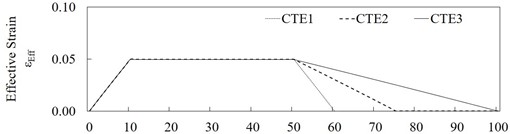
a)
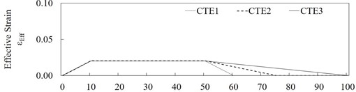
b)
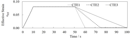
c)
3.1. Mechanism of warping
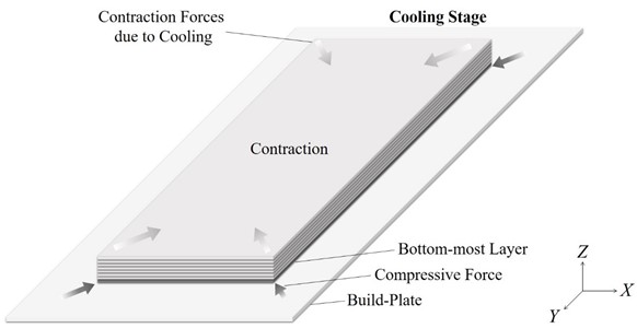
The schematic outline of the warping mechanism is illustrated in Fig. 7. Drastic changes within the material temperature from deposition to cooling stage is thought to induce residual thermal stresses which further increase the internal contraction forces in the material. The contraction forces induced in the upper layers of the 3D-model during the cooling-cycle exerts a compressive force in the bottom-most layer, pulling them away from the build-plate.
The generation of residual thermal stress and corresponding pulling forces within the bottom layer due to non-uniform cooling was reported to lead to permanent distortion and eventually warping [9]. The effect was thought to be further accentuated in specific cases whereby the adhesion forces prevailing between the 3D-model and the build plate would be insufficient to counteract the pulling forces resulting from residual thermal stress [9].
The higher the cooling rate, the greater the pulling force is expected to be as the material contracts at a faster rate. This was evidenced from the fringe plots of effective strain distribution whereby greatest strain build-up in the bottom layers and corners in close contact with the build plate, was observed to occur at higher cooling rates as could be clearly discerned from Figs. 4(a) and 4(b).
From this research study, it could be deduced that the cooling rate has an incidence on the warping behavior of 3D-printed models. The findings of this study were also in line with previous observations made in literature whereby the drastic change in the cooling stage was found to result in a warping behavior in 3D-printed models [9, 19-22].
Fig. 7Schematic outline of the warping mechanism in 3D-printed specimens
3.2. Future recommendation
The numerical modelling of warping in 3D-printed parts can be further extended by investigating other parameters besides the thermal process models such as effect of base temperature and 3D printing speed.
The detailed understanding of changes in 3D-printed components in the post-processing stage of AM with respect to their unique material structure will be beneficial to material engineers and designers.
4. Conclusions
In this study, the effect of printing-cooling cycle on the warping behavior in filament-based 3D-printed models was investigated by considering the finite element method. The warping behavior was investigated by considering and simulating three thermal process models corresponding to distinct variations in the printing-cooling cycles. In terms of the mechanical material parameters, the thermal orthotropic material-model was selected to replicate the non-uniform thermal behavior reported in 3D-prints. The simulated results obtained for each case were dissimilar and variation in effective strain was notably observed in the bottommost layers of the 3D-printed model which was constrained by the build plate. The non-uniform cooling across the various layers of the 3D-model is thought to generate residual thermal stress whereby the corresponding induced pulling forces in the bottom layer would lead to the warping behaviour. Based on the aforementioned research investigation, it can be stated that the printing and cooling stages have a direct influence on the warping behavior of 3D prints.
References
-
N. Shahrubudin, T. C. Lee, and R. Ramlan, “An overview on 3D printing technology: technological, materials, and applications,” Procedia Manufacturing, Vol. 35, pp. 1286–1296, Jan. 2019, https://doi.org/10.1016/j.promfg.2019.06.089
-
E. H. Tümer and H. Y. Erbil, “Extrusion-based 3D printing applications of PLA composites: a review,” Coatings, Vol. 11, No. 4, p. 390, Mar. 2021, https://doi.org/10.3390/coatings11040390
-
T. Duda and L. V. Raghavan, “3D metal printing technology,” IFAC-PapersOnLine, Vol. 49, No. 29, pp. 103–110, Jan. 2016, https://doi.org/10.1016/j.ifacol.2016.11.111
-
R. B. Kristiawan, F. Imaduddin, D. Ariawan, Ubaidillah, and Z. Arifin, “A review on the fused deposition modeling (FDM) 3D printing: filament processing, materials, and printing parameters,” Open Engineering, Vol. 11, No. 1, pp. 639–649, Apr. 2021, https://doi.org/10.1515/eng-2021-0063
-
W. Oropallo and L. A. Piegl, “Ten challenges in 3D printing,” Engineering with Computers, Vol. 32, No. 1, pp. 135–148, Jun. 2015, https://doi.org/10.1007/s00366-015-0407-0
-
M. R. Khosravani, S. Rezaei, H. Ruan, and T. Reinicke, “Fracture behavior of anisotropic 3D-printed parts: experiments and numerical simulations,” Journal of Materials Research and Technology, Vol. 19, pp. 1260–1270, Jul. 2022, https://doi.org/10.1016/j.jmrt.2022.05.068
-
S. Brach, M. Z. Hossain, B. Bourdin, and K. Bhattacharya, “Anisotropy of the effective toughness of layered media,” Journal of the Mechanics and Physics of Solids, Vol. 131, pp. 96–111, Oct. 2019, https://doi.org/10.1016/j.jmps.2019.06.021
-
S. Rezaei, J. R. Mianroodi, T. Brepols, and S. Reese, “Direction-dependent fracture in solids: Atomistically calibrated phase-field and cohesive zone model,” Journal of the Mechanics and Physics of Solids, Vol. 147, p. 104253, Feb. 2021, https://doi.org/10.1016/j.jmps.2020.104253
-
C. Ghnatios and K. Fayazbakhsh, “Warping estimation of continuous fiber-reinforced composites made by robotic 3D printing,” Additive Manufacturing, Vol. 55, p. 102796, Jul. 2022, https://doi.org/10.1016/j.addma.2022.102796
-
N. Bachhar, A. Gudadhe, A. Kumar, P. Andrade, and G. Kumaraswamy, “3D printing of semicrystalline polypropylene: towards eliminating warpage of printed objects,” Bulletin of Materials Science, Vol. 43, No. 1, pp. 1–8, Jul. 2020, https://doi.org/10.1007/s12034-020-02097-4
-
C. Schmutzler, A. Zimmermann, and M. F. Zaeh, “Compensating warpage of 3D printed parts using free-form deformation,” Procedia CIRP, Vol. 41, pp. 1017–1022, Jan. 2016, https://doi.org/10.1016/j.procir.2015.12.078
-
A. Guerrero-De-Mier, M. M. Espinosa, and M. Domínguez, “Bricking: A new slicing method to reduce warping,” Procedia Engineering, Vol. 132, pp. 126–131, Jan. 2015, https://doi.org/10.1016/j.proeng.2015.12.488
-
B. K. O. Cheung and J. P. Carey, “Macromechanics of composite materials,” in Handbook of Advances in Braided Composite Materials, Elsevier, 2017, pp. 307–319, https://doi.org/10.1016/b978-0-08-100369-5.00008-8
-
R. Ramful and A. Sakuma, “Investigation of the effect of inhomogeneous material on the fracture mechanisms of bamboo by finite element method,” Materials, Vol. 13, No. 21, p. 5039, Nov. 2020, https://doi.org/10.3390/ma13215039
-
R. Torre and S. Brischetto, “Experimental characterization and finite element validation of orthotropic 3D-printed polymeric parts,” International Journal of Mechanical Sciences, Vol. 219, p. 107095, Apr. 2022, https://doi.org/10.1016/j.ijmecsci.2022.107095
-
J. L. Faust, P. G. Kelly, B. D. Jones, and J. D. Roy-Mayhew, “Effects of coefficient of thermal expansion and moisture absorption on the dimensional accuracy of carbon-reinforced 3D printed parts,” Polymers, Vol. 13, No. 21, p. 3637, Oct. 2021, https://doi.org/10.3390/polym13213637
-
R. Ramful, T. P. M. Sunthar, W. Zhu, and G. Pezzotti, “Investigating the underlying effect of thermal modification on shrinkage behavior of bamboo culm by experimental and numerical methods,” Materials, Vol. 14, No. 4, p. 974, Feb. 2021, https://doi.org/10.3390/ma14040974
-
R. Ramful, “Numerical simulation of fracture mechanisms due to directional shrinkage in natural composites,” Materials Today: Proceedings, Feb. 2023, https://doi.org/10.1016/j.matpr.2023.02.235
-
A. Armillotta, “Assessment of surface quality on textured FDM prototypes,” Rapid Prototyping Journal, Vol. 12, No. 1, pp. 35–41, Jan. 2006, https://doi.org/10.1108/13552540610637255
-
Peng Anhua Xiao Xingming, “Investigation on reasons inducing error and measures improving accuracy in fused deposition modeling,” International Journal on Advances in Information Sciences and Service Sciences, Vol. 4, No. 5, pp. 149–157, Mar. 2012, https://doi.org/10.4156/aiss.vol4.issue5.18
-
M. S. Alsoufi and A. E. Elsayed, “Warping deformation of desktop 3D printed parts manufactured by open source fused deposition modeling (FDM) system,” International Journal of Mechanical and Mechatronics Engineering, Vol. 17, pp. 7–16, 2017.
-
M. A. Nazan, F. R. Ramli, M. R. Alkahari, M. N. Sudin, and M. A. Abdullah, “Optimization of warping deformation in open source 3D printer using response surface method,” Proceedings of Mechanical Engineering Research Day, pp. 71–72, 2016.
About this article

This research study was funded by the Higher Education Commission, Mauritius under the Individual Research Support Scheme 2021/22.
The datasets generated during and/or analyzed during the current study are available from the corresponding author on reasonable request.
The authors declare that they have no conflict of interest.
