Abstract
Manipulator of the investigated type may move according to a straight line. It has an advantage in the fact that by choosing geometrical parameters of the manipulator it is possible to achieve its effective operation. This is presented by using analytical and graphical methods. The performed research shows that manipulators with vibration impact drives have some positive qualities. In their structure it is not necessary to include the self-stopping mechanism. In the conservative case of the system static position of equilibrium of the impact pair can be with negative, zero or positive tightening. In the case of zero tightening eigenfrequency and period of the system does not depend on the quantity of motion of impact excitation. In the case of harmonic forced excitation resonant motions take place in the vicinity of the eigenfrequency of the conservative system with zero tightening. Analytical – numerical calculations contribute to the creation of manipulators and robots with vibration impact drives.
1. Introduction
Investigation of dynamics of manipulators and robots with vibration impact drive is important in engineering. Manipulator of the investigated type may move according to a straight line. It has an advantage in the fact that by choosing geometrical parameters of the manipulator it is possible to achieve its effective operation. This is presented by using analytical and graphical methods.
The model of the manipulator is described. First, the dynamics of the conservative system is investigated. Results for typical parameters of the manipulator were obtained. Then, the dynamics of the model with forced excitation for various parameters of the manipulator is investigated. The obtained graphical representations show the main dynamic regimes of the manipulator.
The investigation is performed by using analytical – numerical methods of analysis of nonlinear systems.
Resonances of vibrating systems are analyzed in [1]. Dynamics in vibrating systems for various excitations is investigated in [2]. Stabilization of nonlinear systems is described in [3]. Nonlinear effects in vibrating systems are analyzed in [4]. Investigation of periodic orbits is performed in [5]. Analysis of energy transfer is presented in [6]. Investigation of nonlinear interactions is described in [7]. Frequencies of vibrating systems are analyzed in [8]. Investigation of the pendulum mechanism is performed in [9]. Analysis of a piecewise linear system is presented in [10]. Resonant zones of nonlinear systems are described in [11]. Investigation of the Sommerfeld effect is performed in [12]. Analysis of isolated resonances is described in [13]. New types of robots are investigated in [14]. Analysis of the positioning system is performed in [15]. Investigation of the automatic positioning stage is presented in [16]. Analysis of the piezo-driven stage is performed in [17]. Investigation of the precision positioning stage is described in [18]. Analysis of essentially nonlinear dynamics is performed in [19]. Investigation of transmissions is described in [20]. Analysis of robots is performed in [21].
The purpose of the work is to achieve improved operation of the manipulator with vibration impact drive by the choice of structural, geometrical, dynamical parameters for effective operation of the manipulator by using analytical and numerical investigations.
In the conservative case of the system static position of equilibrium of the impact pair can be with negative, zero or positive tightening. Zero tightening is advantageous for practical applications and thus the investigations for zero tightening are performed.
Results of the performed investigation are used in the design of manipulators with vibration impact drive.
2. General dynamic model of the manipulator
The manipulator is shown in Fig. 1. In the figure denotes the immovable coordinate system. By the number 1 the mass is denoted. By the number 2 immovable straight supports are denoted. By the letter coefficient of stiffness of the spring is denoted. By the letter coefficient of viscous damping of the damper of vibrations is denoted. By the exciting force is denoted. By the number 0 the case with the mass is denoted. Further denotes the coefficient of viscous friction between the case and the immovable straight supports. The quantities and denote the displacements shown in the figure. Further the upper dot denotes differentiation with respect to the time variable. The force of resistance of external media to the motion of the case is denoted as , where and are constants and is the velocity of motion of the case.
Fig. 1Model of the system: XOY – the immovable coordinate system; 1 – mass; 2 – immovable straight supports; C – coefficient of stiffness of the spring; H – coefficient of viscous damping of the damper of vibrations; Fωt – the exciting force

In the conservative case of the system static position of equilibrium of the impact pair can be with negative, zero or positive tightening. Zero tightening is advantageous for practical applications and thus the investigations for zero tightening are performed. The distance is the position of equilibrium of the spring.
When the following condition is satisfied:
dynamics of the system is described by the following equations:
where is the amplitude of harmonic excitation and is the frequency of harmonic excitation.
When the following condition is satisfied:
impact of the mass with the mass takes place in a moment of time, where the change of velocities of those masses takes place according to the theorem of quantity of motion and losses of velocity of impact, that is:
where is the coefficient of restitution of the impact. From those equations and are found.
The following notations are introduced:
When the following condition is satisfied:
dynamics of the system is described by the following equations:
When the following condition is satisfied:
impact takes place, that is:
3. Simplified dynamic model with one degree of freedom
First simplified dynamic model of the manipulator with one degree of freedom is investigated.
When the following condition is satisfied:
dynamics of the system is described by the following equation:
When the following condition is satisfied:
impact takes place, that is:
3.1. Conservative system
For the conservative system it is assumed that:
When the following condition is satisfied:
dynamics of the system is described by the following equation:
When the following condition is satisfied:
impact takes place, that is:
Further investigation of the conservative system is performed.
The following parameters of the system are assumed:
The following initial conditions are assumed:
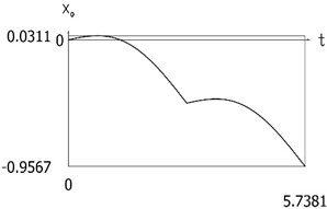
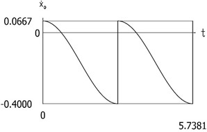
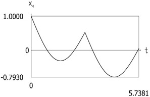
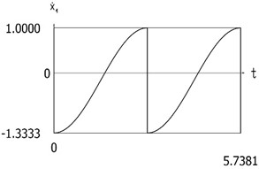
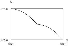
Results for the case of the conservative system are presented in Fig. 2.
Fig. 2Dynamics of the one-dimensional model for the case of the conservative system
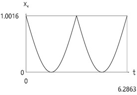
a)
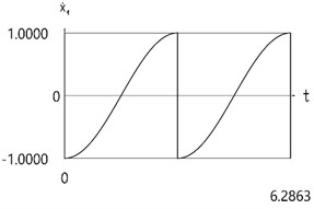
b)
3.2. Investigation of the dynamics of the system
The following parameters of the system are assumed:
The following initial conditions are assumed:
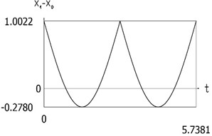
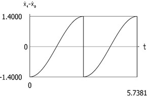
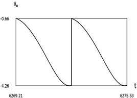
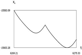
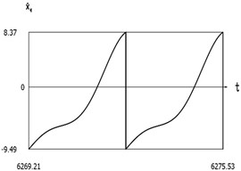
Results of investigation of dynamics are presented in Fig. 3.
Fig. 3Dynamics of the one-dimensional model
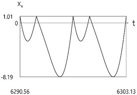
a)
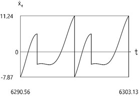
b)
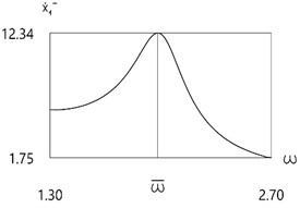
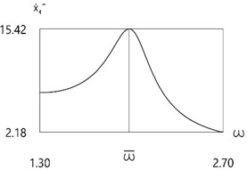
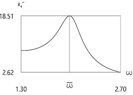
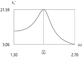
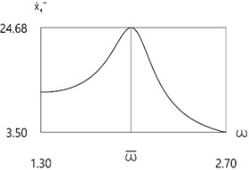
Fig. 4Velocity before impact as function of frequency of excitation
a)
b)
c)
d)
e)
Further investigation of the velocity before impact as function of frequency of excitation is performed.
The following parameters of the system are assumed:
The following initial conditions are assumed:
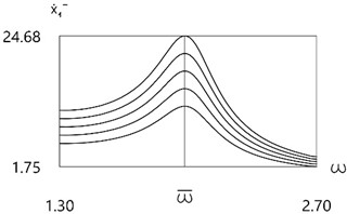
Results for different values of are presented in Fig. 4.
Results for all values of are presented in Fig. 5.
From the presented results in the vicinity of the first resonance the first resonant frequency is observed.
Further the full dynamic model of the manipulator is investigated.
Fig. 5Velocity before impact as function of frequency of excitation for all values of f
4. Conservative system
For the conservative system it is assumed that:
When the following condition is satisfied:
dynamics of the system is described by the following equations:
When the following condition is satisfied:
impact takes place, that is:
Investigation of dynamics is performed according to the Eqs. (29-36). Initial conditions for , , and are to be known. It is convenient to use the point of impact, which is described by the Eqs. (34-36). In those equations for example by freely assuming , , the quantities , , are found. Further according to the Eqs. (30-33) solution till the next impact according to the Eqs. (34-36) is performed and so on.
Further graphical relationships of the variables are obtained, and their analysis is performed as well as of the quantity of motion and of the spectral relationships. From the Eq. (33) it follows that for the conservative system the value of is constant.
Further investigation of the conservative system is performed.
The following parameters of the system are assumed:
The following initial conditions are assumed:
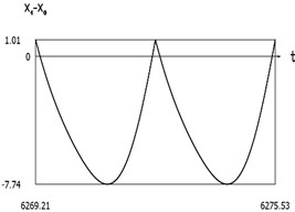
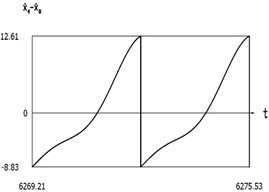
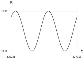
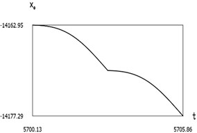
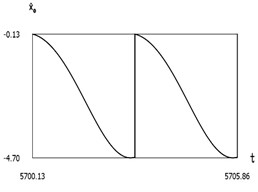
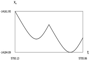
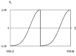
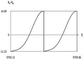
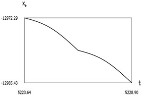
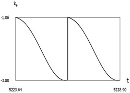
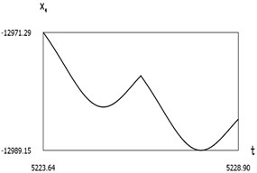
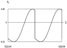
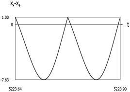
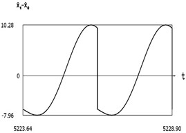
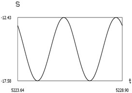
Results for the case of the conservative system are presented in Fig. 6.
From the presented results the period of vibrations of the investigated manipulator is determined.
Fig. 6Dynamics of the manipulator for the case of the conservative system
a)
b)
c)
d)
e)
f)
5. Investigation of the dynamics of the system with external harmonic excitation in the vicinities of resonances
The following parameters of the system are assumed:
The following initial conditions are assumed:
The eigen period was determined as:
The eigenfrequency is:
It is assumed that:
Results for different values of are presented in Fig. 7, Fig. 8, and Fig. 9.
Fig. 7Dynamics of the manipulator when δω = –0.2
a)
b)
c)
d)
e)
f)
g)
From the presented results below the first resonance, at the first resonance and after the first resonance the effectiveness of operation of the manipulator with vibration impact drive at the first resonant frequency is observed.
Further investigation of the quantity of motion during impact as function of frequency of excitation is performed.
Fig. 8Dynamics of the manipulator when δω=0
a)
b)
c)
d)

e)
f)
g)
The following parameters of the system are assumed:
The following initial conditions are assumed:
Results for different values of are presented in Fig. 10.
Fig. 9Dynamics of the manipulator when δω=0.2
a)
b)
c)
d)
e)
f)
g)
From the presented results in the vicinity of the first resonance, the effectiveness of operation of the manipulator with vibration impact drive at the first resonant frequency is observed.
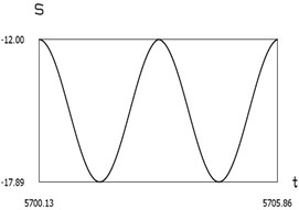
6. Investigation of the harmonics of the conservative system
The following parameters of the system are assumed:
The following initial conditions are assumed:
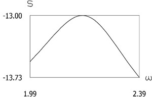
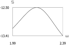
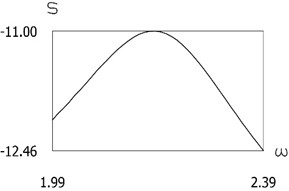
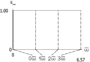
Constant part and the first three harmonics of are presented in Fig. 11.
From the graphical representation the first three eigenfrequencies of the investigated manipulator with vibration impact drive are seen.
Fig. 10Quantity of motion during impact as function of frequency of excitation
a)
b)

c)

d)
e)
Fig. 11Constant part and the first three harmonics of S
7. Conclusions
The proposed 1D manipulator with vibration impact drive is simple because it does not include the self-stopping mechanism and its control is performed by the external force.
In the conservative case of the system static position of equilibrium of the impact pair can be with negative, zero or positive tightening. Zero tightening is advantageous for practical applications and thus the investigations for zero tightening are performed.
In the case of zero tightening eigenfrequency and period of the system does not depend on the quantity of motion of impact excitation. In this case the static position of the system in the position of equilibrium is the point of contact of both masses.
In the case of harmonic forced excitation resonant motions take place in the vicinity of the eigenfrequency of the conservative system with zero tightening.
This enables us to create advanced manipulators and complicated robots from manipulators of this type.
References
-
W. V. Wedig, “New resonances and velocity jumps in nonlinear road-vehicle dynamics,” Procedia IUTAM, Vol. 19, pp. 209–218, Jan. 2016, https://doi.org/10.1016/j.piutam.2016.03.027
-
T. Li, E. Gourc, S. Seguy, and A. Berlioz, “Dynamics of two vibro-impact nonlinear energy sinks in parallel under periodic and transient excitations,” International Journal of Non-Linear Mechanics, Vol. 90, pp. 100–110, Apr. 2017, https://doi.org/10.1016/j.ijnonlinmec.2017.01.010
-
V. A. Zaitsev, “Global asymptotic stabilization of periodic nonlinear systems with stable free dynamics,” Systems and Control Letters, Vol. 91, pp. 7–13, May 2016, https://doi.org/10.1016/j.sysconle.2016.01.004
-
H. Dankowicz and E. Fotsch, “On the analysis of chatter in mechanical systems with impacts,” Procedia IUTAM, Vol. 20, pp. 18–25, Jan. 2017, https://doi.org/10.1016/j.piutam.2017.03.004
-
S. Spedicato and G. Notarstefano, “An optimal control approach to the design of periodic orbits for mechanical systems with impacts,” Nonlinear Analysis: Hybrid Systems, Vol. 23, pp. 111–121, Feb. 2017, https://doi.org/10.1016/j.nahs.2016.08.009
-
W. Li, N. E. Wierschem, X. Li, and T. Yang, “On the energy transfer mechanism of the single-sided vibro-impact nonlinear energy sink,” Journal of Sound and Vibration, Vol. 437, pp. 166–179, Dec. 2018, https://doi.org/10.1016/j.jsv.2018.08.057
-
J. S. Marshall, “Modeling and sensitivity analysis of particle impact with a wall with integrated damping mechanisms,” Powder Technology, Vol. 339, pp. 17–24, Nov. 2018, https://doi.org/10.1016/j.powtec.2018.07.097
-
E. Salahshoor, S. Ebrahimi, and Y. Zhang, “Frequency analysis of a typical planar flexible multibody system with joint clearances,” Mechanism and Machine Theory, Vol. 126, pp. 429–456, Aug. 2018, https://doi.org/10.1016/j.mechmachtheory.2018.04.027
-
U. Starossek, “Forced response of low-frequency pendulum mechanism,” Mechanism and Machine Theory, Vol. 99, pp. 207–216, May 2016, https://doi.org/10.1016/j.mechmachtheory.2016.01.004
-
S. Wang, L. Hua, C. Yang, Y.O. Zhang, and X. Tan, “Nonlinear vibrations of a piecewise-linear quarter-car truck model by incremental harmonic balance method,” Nonlinear Dynamics, Vol. 92, No. 4, pp. 1719–1732, Feb. 2018, https://doi.org/10.1007/s11071-018-4157-6
-
P. Alevras, S. Theodossiades, and H. Rahnejat, “On the dynamics of a nonlinear energy harvester with multiple resonant zones,” Nonlinear Dynamics, Vol. 92, No. 3, pp. 1271–1286, Feb. 2018, https://doi.org/10.1007/s11071-018-4124-2
-
A. Sinha, S. K. Bharti, A. K. Samantaray, G. Chakraborty, and R. Bhattacharyya, “Sommerfeld effect in an oscillator with a reciprocating mass,” Nonlinear Dynamics, Vol. 93, No. 3, pp. 1719–1739, Apr. 2018, https://doi.org/10.1007/s11071-018-4287-x
-
G. Habib, G. I. Cirillo, and G. Kerschen, “Isolated resonances and nonlinear damping,” Nonlinear Dynamics, Vol. 93, No. 3, pp. 979–994, Apr. 2018, https://doi.org/10.1007/s11071-018-4240-z
-
V. Glazunov, New mechanisms in contemporary robot engineering. Moscow: Tehnosphere, 2018.
-
H. Shinno, H. Yoshioka, and H. Sawano, “A newly developed long range positioning table system with a sub-nanometer resolution,” CIRP Annals, Vol. 60, No. 1, pp. 403–406, Jan. 2011, https://doi.org/10.1016/j.cirp.2011.03.027
-
W. Kokuyama, T. Shimoda, and H. Nozato, “Primary accelerometer calibration with two-axis automatic positioning stage,” Measurement, Vol. 204, p. 112044, Nov. 2022, https://doi.org/10.1016/j.measurement.2022.112044
-
K. Cai, Y. Tian, F. Wang, D. Zhang, and B. Shirinzadeh, “Development of a piezo-driven 3-DOF stage with T-shape flexible hinge mechanism,” Robotics and Computer-Integrated Manufacturing, Vol. 37, pp. 125–138, Feb. 2016, https://doi.org/10.1016/j.rcim.2015.07.004
-
C. Lin, M. Jiang, and S. Zheng, “Establishment and verification of the analytical model for the critical parameters in the kinematics model of the precision positioning stage,” Sensors and Actuators A: Physical, Vol. 320, p. 112572, Apr. 2021, https://doi.org/10.1016/j.sna.2021.112572
-
V. Ragulskienė, Vibro-Shock Systems (Theory and applications). Vilnius: Mintis, 1974.
-
R. Kurila and V. Ragulskienė, Two-Dimensional Vibro-Transmissions. Vilnius: Mokslas, 1986.
-
Ragulskis et al., Vibromotors for Precision Microrobots. New York: Hemisphere, 1987.
About this article

The authors have not disclosed any funding.
The datasets generated during and/or analyzed during the current study are available from the corresponding author on reasonable request.
Kazimieras Ragulskis: conceptualization, formal analysis, investigation, methodology, supervision, validation, visualization, writing – original draft preparation, writing – review and editing. Liutauras Ragulskis: visualization.
The authors declare that they have no conflict of interest.
