Abstract
To simulate the dynamic rocking responses of free-standing rigid blocks on a flexible foundation with a slope, a modified concentrated spring model (CSM) is proposed. The shaking table model test of a rigid steel frame structure was conducted, and the test results indicated that the rocking response of the structure can be effectively predicted by the proposed model. Utilizing the modified CSM, the interaction effects between the structure and foundation on the rocking of the free-standing rigid blocks on a flexible foundation with a slope were investigated. The influences of spring stiffness, viscous damping, and the frictional coefficient on the rocking of the rigid blocks under pulse-type ground motions were analyzed numerically. The results indicated that decreasing the spring stiffness and increasing the viscous damping coefficient of the modified CSM can reduce the number of impacts and rocking duration, while the friction coefficient has a significantly non-linear effect on the rocking response.
1. Introduction
The concept of rocking structures involves their propensity to exhibit rocking vibrations when subjected to seismic events, with energy dissipation primarily occurring through collisions during these vibrations. Rocking structures typically experience minimal damage during earthquakes, with instances where the main structure remains entirely unscathed. The pioneering work of Housner in 1963 introduced the first model for simulating the rocking of a freestanding rigid block on a rigid horizontal foundation [1]. This model can be used to explain the movement of masonry structures [2-5], the seismic response of anchorage-free equipment [6-8], the stability of ancient temples that have stood in earthquake-prone areas for more than 2,500 years [9], and so on. This rocking system with self-centering ability has been integrated into buildings [10-14] and bridges [15] to enhance the seismic resilience of structures.
Based on the Housner’s model, extensive research has been conducted on rocking structures. Aslam et al. [16] conducted both analytical and experimental studies, highlighting how variables such as aspect ratio, size, and the coefficient of restitution critically influence the response of rigid blocks during seismic activities. Anooshehpoor et al. [17] provided analytical solutions outlining the rocking and overturning dynamics of symmetric two-dimensional rigid blocks subjected to a full sine wave of horizontal ground motion acceleration. This solution yielded a lower bound estimate for the peak ground acceleration at Point Reyes Station California, during the 1906 San Francisco earthquake, which caused the San Francisco-bound train to derail. Zhang and Makris [18] further refined the analytical solution, demonstrating that free-standing blocks can overturn either through impact events or without impacts when subjected to cycloidal pulses. A safe operational zone within the acceleration-frequency plane was defined, derived from the minimum overturning acceleration spectrum. Casapulla [19] explored resonance spectra to illustrate the impact of ground motion characteristics and system parameters on rocking dynamics. To investigate the slope base effect on the rocking block, a novel model was developed by Lv et al. [20], introducing the slope angle to Housner’s model. Li et al. [21] analyzed the dynamic response of free-rocking piers based on the Housner model, and further proposed the design method based on the equal displacement rocking spectrum.
Despite extensive investigations primarily focusing on rigid rocking blocks atop rigid foundations, recent findings underscore the significant influence of foundation characteristics on seismic rocking behavior. Researchers have adapted models, including the Winkler foundation [22, 23] and the simpler “two-spring” foundation [24] models, to capture the role of foundation flexibility. However, these traditional models often overlook complexities such as sliding and nonlinear behavior. To address this, Palmeri and Makris [25] presented a robust nonlinear formulation based on a CSM, enabling deeper insights into the response of rocking structures on viscoelastic foundations. Experimental investigations by ElGawady et al. [26] indicated that the choice of interface materials profoundly affects the dynamic behavior of rocking blocks, with rubber substrates proving superior for energy dissipation compared to concrete and timber. Additionally, a novel nonlinear model was developed to describe the interactions between rocking blocks and a nonlinear flexible base, incorporating Hunt and Crossley’s nonlinear impact force model. This advancement enables a more accurate depiction of the nonlinear behavior of rocking blocks placed on softer foundation materials [27]. To examine the survival probability of the rigid rocking under random excitations, an analytical approach utilizing static condensation and stochastic linearization techniques was adopted [28]. In the context of soil-structure interaction during earthquake events, Raychowdhury and Hutchinson [29] presented a beam-on-nonlinear-Winkler-foundation (BNWF) model, proficiently predicting footing responses in terms of shear forces, settlements, moment distributions, and rotational demands. Building on this body of work, Lu et al. [30] developed an enhanced Winkler foundation model by introducing nonlinear hysteretic elements to the traditional Winkler foundation model in order to predict the seismic response of a rocking isolation structure considered as a rigid rocking block situated on a uniform clay substrate. Masaeli et al. [31]explored the seismic responses of mid-rise to high-rise structures founded on various soils, assessing the implications of nonlinear soil-structure interaction (SSI) on shear-type buildings.
The dynamic response of rocking blocks on viscoelastic foundations can be influenced by various factors such as system parameters [32-34], foundation characteristics, earthquake ground motion [35-37], and so on. Among these interactions, the behavior of rigid blocks undergoing free-standing rocking on sloped foundations has been somewhat overlooked in existing literature. Lv et al. [20] examined how slope affects the seismic behavior of rocking blocks that are standing freely on slopes. Notably, their investigation involved a symmetric rocking block resting on a rigid foundation. In contrast, Li et al. [38] introduced a modified CSM to represent the dynamic responses of non-symmetric rocking blocks standing freely on a sloped viscoelastic foundation. Their research explored how both the slenderness of the rocking block and the angle of the sloped foundation impact seismic rocking behavior. However, the effects of spring stiffness, viscous damping or friction coefficient on their rocking response were not explored in depth. Here, a shaking table test on a rigid steel frame was conducted to verify the effectiveness of the proposed model in reference [38]. Based on the validated model, the influences of spring stiffness, viscous damping and friction coefficient on the rocking response of rigid non-symmetric block located on a sloped viscoelastic foundation were analyzed numerically.
2. Modified concentrated springs model
The analysis of an asymmetric rigid rocking block supported by a sloped flexible base diverges significantly from the predicted model proposed by Housner [1], which assumes that rocking blocks are situated on rigid, horizontal base. In this context, the rocking response of the rigid block can be influenced by the interaction between the structure and base. Fig. 1 illustrates the configurations of a non-symmetric rigid rocking block resting on two different types of viscoelastic foundations: one without slope, as shown in Fig. 1(a), and the other with a slope, depicted in Fig. 1(b). The slope angle is defined as positive when the foundation rotates in a clockwise direction. Furthermore, the physical significance of the geometric parameters in Fig. 1 aligns with the definitions provided in reference [38]. In Fig. 1, is the mass of the rigid rocking block, and are slenderness ratios of the block compared to the left corner A and right corner B, respectively, with their complementary angles denoted as and . The acceleration due to gravity is denoted as . is the rotation angle of the mass center of the block. and are the vertical deformations at the corners A and B, respectively. and denote the external forces applied in the vertical direction and horizontal direction, respectively. and are the spring stiffness coefficients of the modified CSM, respectively. and are the damping coefficient for the modified CSM, respectively. and indicate the frictional forces at the corners A and B, respectively. The frictional forces and , depending on the stick or sliding state at points A and B and the friction coefficient , can be calculated using the analytical formulas from reference [38]. When base is horizontal, the analysis of frictional force aligns with that presented in reference [39], making it a particular scenario within this study.
Fig. 1Asymmetrical rigid block free-standing on flexible foundation: a) without slope and b) with slope [38]
![Asymmetrical rigid block free-standing on flexible foundation: a) without slope and b) with slope [38]](https://static-01.extrica.com/articles/24645/24645-img1.jpg)
a)
![Asymmetrical rigid block free-standing on flexible foundation: a) without slope and b) with slope [38]](https://static-01.extrica.com/articles/24645/24645-img2.jpg)
b)
The equations of motion for the non-symmetric rocking block on the sloped flexible base can be formulated as follows [38]:
where is the inertia of the block, and are the horizontal displacements at the base supporting the left and right corners, respectively. The vertical deformation , vertical velocities , horizontal displacement , and horizontal velocities of the two corners A and B can be directly expressed in terms of , , , and .
In Eq. (1), the stiffness coefficients and damping coefficient of the modified CSM can be expressed as [38]:
where and are the initial elastic stiffness of the springs 1 and 2 in the modified CSM, respectively. and are the and viscous damping for the modified CSM. More details of the modified CSM can be found in reference [38].
3. Shaking table test and model validation
3.1. Shaking table test
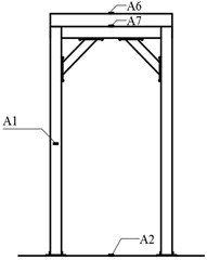
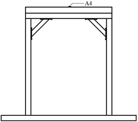
To validate the proposed modified CSM, a shaking table model test was performed in the Tianjin Key Laboratory of Civil Structure Protection and Reinforcement. The uni-directional shaking table depicted in Fig. 2 can replicate white noise, sinusoidal wave, and earthquake ground motion with a peak displacement of up to 100 mm, a peak velocity of up to 0.9 m/s, and a peak acceleration of up to 2 g, accommodating a maximum specimen weight of 500 kg. The dimensions of the shaking table are 1 m×1 m. The test frequency of the shaking table is from 0.1 Hz to 100 Hz. The maximum overturning moment of the shaking table is 10 kN∙m. A frame structure made of Q345 steel was selected as an experimental model to simulate the rigid block. To meet the requirement of an approximate rectangular rigid block during the structure’s rocking motion, the dimensions of the test model were 640 mm×440 mm×800 mm, as illustrated in Fig. 3. The input signal of the shaking table was a sine wave with the amplitude of 1 m/s2 and frequencies of 4 Hz and 5 Hz respectively.
Fig. 2Shaking table model test
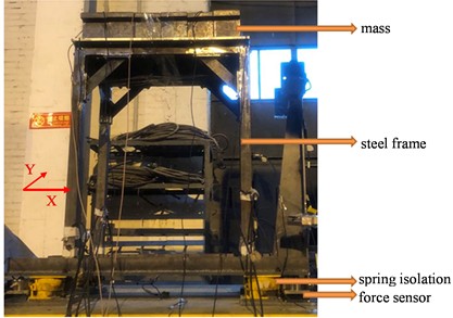
Fig. 3Dimensions of the steel frame model (Unit: mm)
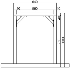
a) Front view
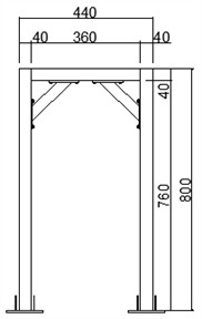
b) Side view
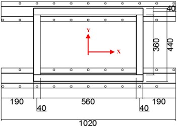
c) Plan view
3.2. Spring isolator
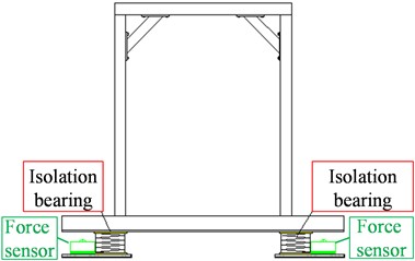
The steel frame and the shaking table are connected by four spring isolation bearings, and a mass with a weight of 300 kg is attached to the top of the model. The spring bearing produced by Geergu (Qingdao) Vibration Control Co., Ltd. was selected, and the bearing type is KS-A180. To obtain the stiffness of the four spring isolations, the compression test of the bearings is carried out by Shimadzu equipment in the Material Laboratory of Tianjin Chengjian University, as shown in Fig. 4. The stiffness of No. 1 bearing, No. 2 bearing, No. 3 bearing, and No. 4 bearing is 79.383 N/mm, 90.629 N/mm, 83.627 N/mm and 91.89 N/mm, respectively. In the test, the slope angle was 0, which was one special case of the proposed model. The influence of structural eccentricity on its dynamic rocking response was studied by changing the position of the spring bearings. The layout of the spring isolation bearings and the force sensors is shown in Fig. 5. The operating conditions of L3R1 and L3R2 are selected to verify the effectiveness of the model. The operation condition of L3R1 is that the left bearings are arranged at the position of 3 in Fig. 5, and the right bearings are arranged at the position of 1 in Fig. 5. The operation condition of L3R2 is that the left bearings are arranged at the position of 3 in Fig. 5, and the right bearings are arranged at the position of 2 in Fig. 5. The vertical spring isolation bearings are arranged as shown in Fig. 6.
Fig. 4The compression test of the spring isolation bearing
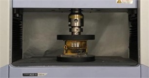
Fig. 5Layout of the spring isolation bearings and the pressure sensors
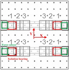
Fig. 6Shaking table model with spring isolation bearings
3.3. Instrumentation
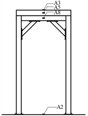
In the shaking table test, PCB piezoelectric accelerometer was used to measure the acceleration response of rigid frame. The accelerometers are list in Table 1. The layout of accelerometers is shown in Fig. 7. To measure the displacement response of rigid frame, OptoNCDT series laser triangular reflection displacement sensor was set at a position about 70 mm outside the frame. There was no actual contact between the displacement meter and the test specimen during the shaking table test. The non-contact laser displacement meter can ensure high-precision measurement without loss and interference.
Table 1List of the accelerometers
Number | Accelerometer | Sensitivity | Transverse sensitivity | Position | Direction of accelerometer |
1 | 352B 224174 | 986 mV/g | 1.4 % | Mid of right column | |
2 | 352B 224174 | 986 mV/g | 1.5 % | Center of platform | |
3 | 352B 224175 | 988 mV/g | 1.4 % | Left side of mass top | |
4 | 333B30 LW67198 | 103.3 mV/g | 1.6 % | Center of mass top | |
5 | 333B30 LW67197 | 99.5 mV/g | 0.3 % | Left side of mass | |
6 | 352B 220884 | 978 mV/g | 0.8 % | Right side of mass top | |
7 | 352B 220860 | 978 mV/g | 1.4 % | Left side of mass | |
8 | 352B 222196 | 965 mV/g | 1.4 % | The left beam of the frame |
Fig. 7Accelerometer arrangement
a) Left elevation
b) Right elevation
c) Front elevation
3.4. Model validation
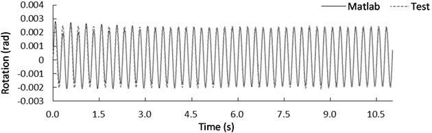
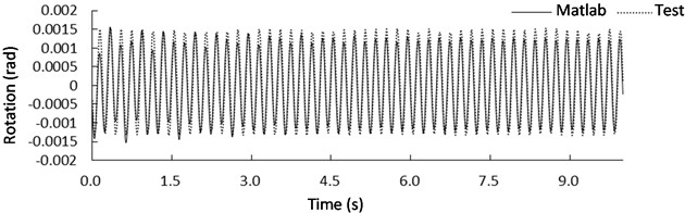
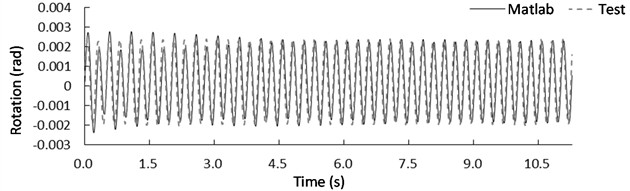
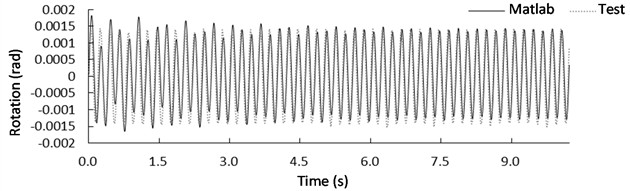
To verify the model proposed in this paper, the structures excited by the 4 Hz and 5 Hz sine waves with a peak acceleration of 1 m/s2 under the conditions of L3R1 and L3R2 were selected as the object. Compared with the numerical analysis results, the centroid angle measured by shaking table test is analyzed. The width of the rigid block is 640 mm, and the height of the rigid block is 800 mm. The stiffness of spring 1 for the modified CSM is 1.63012×10⁵ N/m, which is the total stiffness of the No. 1 bearing and No. 3 bearing. The stiffness of spring 2 for the modified CSM is 1.82519×10⁵ N/m, which is the total stiffness of the No. 2 bearing and No. 4 bearing. The viscous damping is 1.511×10³ N/m/s, and the viscous damping is 1.598×10³ N/m/s. When the isolation bearings are positioned at L3R1, the center of mass undergoes rotational movement as depicted in Fig. 8 when subjected to a sine wave excitation. Fig. 8(a) shows the rotational response of the structure when excited by a sine wave with a frequency of 4 Hz and a peak acceleration of 1 m/s2. Fig. 8(b) illustrates the rotational response of the structure under a sine wave excitation with a frequency of 5 Hz and a peak acceleration of 1 m/s2. The comparison between the shaking table test and numerical simulation results is listed in Table 2. The rotation angle error can be calculated as follows: (experimental value- numerical value)/ numerical value × 100 %. When the frequency of the sinusoidal excitation signal was 4 Hz, the maximum rotation angle obtained from the shaking table test was 0.0026 rad, the maximum rotation angle of numerical simulation was 0.00281 rad, the minimum rotation angle obtained from the shaking table test was –0.00231 rad, and the minimum rotation angle obtained from numerical simulation of the modified CSM was –0.00209 rad. The rotation angle error between shaking table test and numerical results were –7.473 % and 10.526 % respectively. When the frequency of the sinusoidal excitation signal was 5 Hz, the maximum rotation angle obtained from the shaking table test was 0.00153 rad, the maximum rotation angle of numerical simulation was 0.00156 rad, the minimum rotation angle obtained from the shaking table test was –0.00133 rad, and the minimum rotation angle of numerical simulation was –0.00153 rad. The rotation angle error (Table 2) between shaking table test and numerical results were –1.923 % and 13.072 % respectively.
Fig. 8Rotation response of the mass center for case L3R1 under sine wave with a frequency of: a) 4 Hz and b) 5Hz
a)
b)
Table 2Rotation peak of mass center for case L3R1
Sine | 4 Hz | 5 Hz | ||
Max. | Min. | Max. | Min. | |
Test | 0.00260 | –0.00231 | 0.00153 | –0.00133 |
Numerical | 0.00281 | –0.00209 | 0.00156 | –0.00153 |
Error (%) | –7.473 | 10.526 | –1.923 | –13.072 |
Similarly, when the isolation bearings were at position L3R2, the rotation angle of the center of mass is shown in Fig. 9 under the sine wave excitation. Fig. 9(a) displays the rotational response of the structure excited by a sine wave with a frequency of 4 Hz and a peak acceleration of 1 m/s2, while Fig. 9(b) shows the rotational response under a sine wave excitation with a frequency of 5 Hz and a peak acceleration of 1 m/s2. When the frequency of the sinusoidal excitation signal was 4 Hz, the maximum rotation angle obtained from the shaking table test was 0.00259 rad, the maximum rotation angle of numerical simulation was 0.00238 rad, the minimum rotation angle obtained from the shaking table test was –0.00228 rad, and the minimum rotation angle of numerical simulation was –0.00208 rad. The rotation angle error between shaking table test and numerical results were 8.824 % and 9.615 % respectively. When the frequency of the sinusoidal excitation signal was 5 Hz, the maximum rotation angle obtained from the shaking table test was 0.00143 rad, the maximum rotation angle of numerical simulation was 0.00182 rad, the minimum rotation angle obtained from the shaking table test was –0.00154 rad, and the minimum rotation angle of numerical simulation was –0.00165 rad. The rotation angle error (Table 3) between shaking table test and numerical results were –21.429 % and 6.667 % respectively. The error may be caused by external interference during shaking table testing and errors in data acquisition.
Fig. 9Rotation response of the mass center for case L3R2 under sine wave with a frequency of: a) 4 Hz and b) 5Hz
a)
b)
By comparison and analysis, it can be found that the error between experimental results and numerical simulation analysis fluctuates around 10 %, which verified the effectiveness of the modified concentrated springs model. The proposed model can be used to predict the rocking response of free-standing rigid blocks on flexible foundation.
Table 3Rotation peak of mass center for case L3R2
Sine | 4 Hz | 5 Hz | ||
Max. | Min. | Max. | Min. | |
Test | 0.00259 | –0.00228 | 0.00143 | –0.00154 |
Numerical | 0.00238 | –0.00208 | 0.00182 | –0.00165 |
Error (%) | 8.824 | 9.615 | –21.429 | –6.667 |
4. Parametric analysis
In this section, a non-symmetric block, with a mass of 1500 kg, a length of 1.6065 m measured from the center of mass to corner point A, = 0.2 rad and = 0.4 rad, was selected for the numerical analysis. In the modified CSM, the following parameters are established for analytical assessment: the spring stiffness coefficients were 1.31×10⁸ N/m, and the viscous damping coefficients were 2.87×10⁵ N·s/m. Furthermore, the friction coefficient was assigned a value of 0.625. The previous findings indicated that in addition to the slope angle effect, the rocking response of a non-symmetric block when placed on a flexible base can be impacted by the slope’s direction [38]. Specifically, when was larger than , the rocking behavior of the block on a flexible base with a slope angle of 0.05 rad was larger than that of –0.05 rad. Consequently, a base with a 0.05 rad slope angle was chosen for the subsequent parameter analysis. This section will explore the effects of structure-foundation interaction on the rocking response of free-standing rigid rocking blocks situated on a sloped flexible base, focusing specifically on spring stiffness, viscous damping, and the friction coefficient.
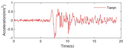
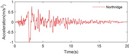
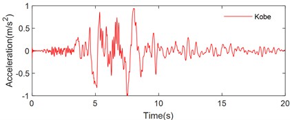
To assess the performance of the rocking block on a sloped flexible base, three representative pulse-like ground motion recorded during historical seismic events, the Tianjin, Northridge and Kobe earthquakes, were selected for excitation. The acceleration time history curves for these earthquake ground motions are presented in Fig. 10.
Fig. 10Pulse-type ground motions: a) Tianjin, b) Northridge, c) Kobe
a)
b)
c)
4.1. Spring stiffness
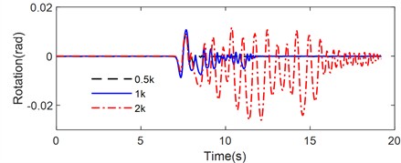
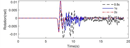
Fig. 11 illustrates the rotation time history of the rocking block on a sloped flexible base with different spring stiffness subjected to various pulse-type earthquakes, including Tianjin, Northridge, and Kobe earthquakes. The peak rotation, number of impacts and maximum half-cycle rocking period during the rocking are listed in Table 4.
Table 4Rocking response of the rigid block with different spring stiffness
Earthquakes | Peak rotation(rad) | Number of impacts | Maximum half-cycle rocking period (s) | ||||||
0.5k | 1k | 2k | 0.5k | 1k | 2k | 0.5k | 1k | 2k | |
Tianjin | –0.0089 | 0.0107 | –0.0261 | 16 | 38 | 52 | 0.738 | 0.4320 | 0.6820 |
Northridge | –0.0397 | –0.0313 | –0.0766 | 28 | 30 | 32 | 0.8664 | 0.8282 | 1.0246 |
Kobe | –0.1518 | –0.1135 | –0.1097 | 34 | 48 | 60 | 1.4 | 1.153 | 1.0954 |
As illustrated in Fig. 11, the seismic responses of the non-symmetrical rigid rocking block were significantly influenced by the spring stiffness of the modified CSM. Fig. 11(a) presents the rocking behavior of the rigid block subjected to the Tianjin earthquake excitation, characterized by a peak acceleration of 0.35g. For the configuration with a spring stiffness of 0.5k, the peak rotation angle was –0.0089 rad. As spring stiffness of the two-spring foundation increased, the absolute values of the peak rotations also rose, reaching 0.0107 rad for a stiffness of 1k and 0.0261 rad for 2k. Notably, the direction of rocking producing the peak rotation for the 1k stiffness was opposite to that observed in the 0.5k and 2k cases. The number of impacts experienced by the rigid block increased progressively with the spring stiffness, with values of 16, 38, and 52 impacts for stiffness levels of 0.5k, 1k, and 2k, respectively. The maximum half-cycle rocking periods were 0.738 s, 0.432 s, and 0.682 s for 0.5k, 1k, and 2k, respectively. The duration of rocking was longest for the configuration with 2k stiffness, followed by 1k, while the shortest duration occurred for the 0.5k case. Additionally, the energy dissipation was most rapid for the rigid rocking block resting on the inclined flexible base with a spring stiffness of 0.5k.
Fig. 11Rotation time history of a rigid block on a flexible foundation with different spring stiffness under ground motion: a) Tianjin, b) Northridge and c) Kobe
a)
b)
c)
Under the Northridge earthquake excitation (Fig. 11(b)), the peak rotations for the rigid block with spring stiffnesses of 0.5k, 1k, and 2k were –0.0397 rad, –0.0313 rad, and –0.0766 rad, respectively. The corresponding impact numbers were 28, 30, and 32. The maximum half-cycle rocking periods were recorded as 0.8664 s, 0.8282 s, and 1.0246 s for 0.5k, 1k, and 2k. Consistent with previous observations, the longest rocking duration was noted for 2k stiffness, followed by 1k, while the cessation of rocking occurred earliest for 0.5k, confirming that energy dissipation was fastest in this case.
During the Kobe earthquake excitation (Fig. 11(c)), the peak rotations for the rigid block with spring stiffnesses of 0.5k, 1k, and 2k were –0.1518 rad, –0.1135 rad, and –0.1097 rad, respectively, indicating a decrease in peak rotation with increasing spring stiffness of the two-spring foundation. The number of impacts for these stiffness levels was recorded at 34, 48, and 60, respectively. The maximum half-cycle rocking periods were 1.4 s, 1.153 s, and 1.0954 s for the respective stiffnesses. Again, the rocking duration was longest for the 2k stiffness case, followed by 1k, while the rigid block with 0.5k stiffness stopped rocking first. The energy dissipation of the rigid rocking block on the flexible base with a spring stiffness of 0.5k was the most rapid, and the block stopped rocking and stabilized the fastest.
The rocking response of a rigid block under three pulse-like earthquake excitations showed that the effect of the spring stiffness of the modified CSM on the rocking behavior of a rigid block resting on inclined flexible base was significantly non-linear. Furthermore, as the spring stiffness increased, the impact number increased accordingly, the rocking duration was prolonged, and the energy dissipation was reduced.
4.2. Viscous damping
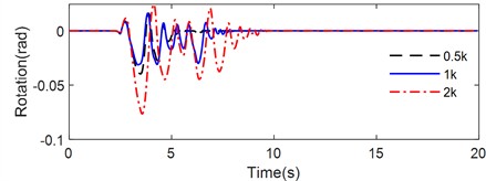
Fig. 12 illustrates the rotation time history of the rigid rocking block on a flexible base with different viscous damping subjected to various pulse-type earthquakes. The peak rotation, number of impacts and maximum value of half-cycle rocking period are listed in Table 5.
Fig. 12Rotation time history of rigid block on flexible foundation with different viscous damping under ground motion: a) Tianjin, b) Northridge, c) Kobe
a)
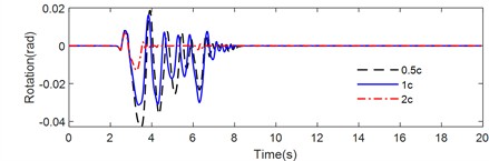
b)
c)
Table 5Rocking response of the rigid block with different viscous damping
Earthquakes | Peak rotation (rad) | Number of impacts | Maximum half-cycle rocking period (s) | ||||||
0.5c | 1c | 2c | 0.5c | 1c | 2c | 0.5c | 1c | 2c | |
Tianjin | –0.0125 | 0.0107 | 0.0107 | 106 | 38 | 12 | 0.548 | 0.432 | 0.478 |
Northridge | –0.0428 | –0.0313 | –0.0130 | 46 | 30 | 26 | 0.8828 | 0.8282 | 0.6674 |
Kobe | –0.0777 | –0.0888 | –0.0683 | 62 | 42 | 32 | 0.9738 | 1.0312 | 1.0830 |
As illustrated in Fig. 12 and summarized in Table 5, the rocking responses of the non-symmetrical block on an inclined flexible base were significantly impacted by the viscous damping characteristics of the two-spring foundation. Under the Tianjin earthquake excitation (Fig. 12(a)), the peak rotation angle of the non-symmetrical rigid block on the inclined flexible base with viscous damping of 0.5c was –0.0125 rad, while the peak rotation angles for the coefficients of 1c and 2c were 0.0107 rad, indicating a reversal in the direction of the peak rotation angle. Notably, the number of impacts of the rigid block decreased progressively with the increase in viscous damping: specifically, 106 impacts occurred at 0.5c, 38 at 1c, and 12 at 2c. The maximum half-cycle rocking periods were 0.548 s, 0.432 s, and 0.478 s for the two-spring foundation with viscous damping of 0.5c, 1c, and 2c, respectively. The longest rocking duration was observed for the 0.5c case, followed by 1c, while the shortest duration was associated with 2c. This behavior suggested that energy dissipation was most rapid for the rigid rocking block on the inclined flexible base with a damping coefficient of 2c. Furthermore, the variations in the maximum rotation angle and maximum half-cycle rocking period indicated that viscous damping exerted a significant non-linear effect on the rocking response.
During the Northridge earthquake excitation (Fig. 12(b)), the peak rotations for the rigid rocking block on the inclined flexible base with viscous damping of 0.5c, 1c, and 2c were –0.0428 rad, –0.0313 rad, and –0.0130 rad, respectively. As viscous damping of the modified CSM increased, the peak rotation angle decreased. The corresponding numbers of impacts were 46, 30, and 26, which decreased with the increase of viscous damping of the two-spring foundation. Additionally, the maximum half-cycle rocking periods also decreased with the increase of viscous damping, which were 0.8828 s, 0.8282 s, and 0.3374 s for the two-spring foundation with viscous damping of 0.5c, 1c, and 2c, respectively. The longest duration of rocking was once again noted for the 0.5c condition, while the shortest was found at 2c, further supporting the conclusion that energy dissipation was most rapid at the highest damping coefficient.
Under the Kobe earthquake excitation (Fig. 12(c)), the peak rotations for the rigid rocking block on the inclined flexible base with viscous damping of 0.5c, 1c, and 2c were –0.0777 rad, –0.0888 rad, and –0.0683 rad, respectively. Notably, the maximum peak rotation angle occurred at the 1c damping coefficient, while the maximum value of the half-cycle rocking period was longest at 2c. As with previous excitation cases, the number of impacts decreased with increasing viscous damping: 62 impacts were observed at 0.5c, 42 at 1c, and 32 at 2c. The rocking duration followed the same trend, being longest for the 0.5c case, followed by the 1c, with the shortest observed for 2c. These observations consistently indicate that energy dissipation is most rapid for the rocking block located on the inclined flexible base with a viscous damping coefficient of 2c.
In summary, the numerical analysis revealed that the rocking behavior of the rigid rocking block on an inclined flexible base during pulse-like earthquake events can be influenced by the viscous damping characteristics of the modified CSM, and the effect is significantly non-linear. Furthermore, the number of impacts and the rocking durations decreased with higher damping, with the shortest durations linked to the highest damping levels.
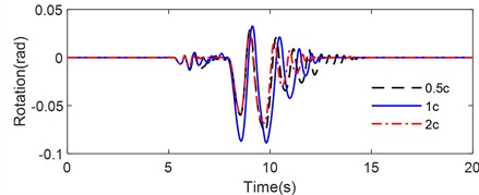
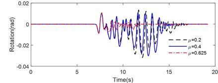
4.3. Frictional coefficient
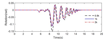
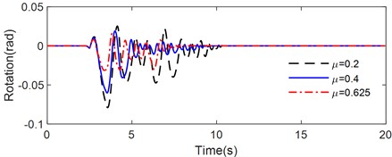
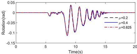
Fig. 13 illustrates the rotation time history of the rocking block on a sloped flexible base with different frictional coefficient subjected to various pulse-type earthquakes, including Tianjin, Northridge, and Kobe earthquake. The peak rotation, number of impacts and maximum value of the half-cycle rocking period are listed in Table 6.
Table 6Rocking response of the rigid block with different frictional coefficient
Earthquakes | Peak rotation (rad) | Number of impacts | Maximum half-cycle rocking period (s) | ||||||
0.2 | = 0.4 | = 0.625 | = 0.2 | = 0.4 | = 0.625 | = 0.2 | = 0.4 | = 0.625 | |
Tianjin | –0.0317 | –0.0301 | 0.0107 | 54 | 40 | 38 | 0.650 | 0.6360 | 0.4320 |
Northridge | –0.0790 | –0.0602 | –0.0312 | 32 | 40 | 30 | 1.0314 | 0.9554 | 0.8282 |
Kobe | –0.1077 | –0.1135 | –0.1135 | 46 | 46 | 48 | 1.2428 | 1.2726 | 1.1530 |
As illustrated in Fig. 13, the rocking responses of the non-symmetrical block positioned on an inclined flexible base were significantly influenced by the friction coefficient between the block and the foundation. Under the excitation of the Tianjin earthquake (Fig. 13(a)), the peak rotation angle of the rocking block, which was resting on the inclined flexible base with a friction coefficient of 0.2, reached –0.0317 rad. An increase in the friction coefficient led to a decrease in the absolute value of the peak rotation angle, which was measured at 0.0301 rad for a coefficient of 0.4 and 0.0107 rad for a coefficient of 0.625. Notably, at a friction coefficient of 0.625, the peak rotation angle reversed direction. Furthermore, the number of impacts and the maximum half-cycle rocking periods observed also decreased progressively with increasing friction coefficients: 54 impacts occurred at 0.2, while the number diminished to 40 at 0.4 and 38 at 0.625. The corresponding maximum half-cycle rocking periods were 0.65 s, 0.636 s, and 0.432 s for friction coefficients of 0.2, 0.4, and 0.625, respectively. The shortest duration of rocking occurred at a coefficient of 0.625, followed by 0.4, while the longest duration of rocking occurred at a coefficient of 0.2. The results indicated that the energy dissipation was related to the coefficient of friction, with higher coefficients resulting in more rapid energy dissipation under Tianjin earthquake excitation.
Fig. 13Rotation time history of rigid block on flexible foundation with different frictional coefficient under ground motion: a) Tianjin, b) Northridge, c) Kobe
a)
b)
c)
Similarly, under the Northridge earthquake excitation (Fig. 13(b)), the peak rotation angle of the non-symmetrical block on the inclined flexible base decreased with the increase of the friction coefficient between the rigid block and the foundation. The peak rotation angle corresponding to friction coefficients of 0.2, 0.4 and 0.625 were –0.0790 rad, –0.0602 rad and –0.0312 rad, respectively. The maximum number of impacts was found at a friction coefficient of 0.4, with 32, 40 and 30 impacts at friction coefficients of 0.2, 0.4 and 0.625, respectively. The maximum half-cycle rocking periods were recorded as 1.0314 s, 0.9554 s, and 0.8282 s. The longest rocking duration was at a coefficient of 0.2, followed closely by 0.4, while the shortest duration corresponded to 0.625. These results indicate that energy dissipation is similarly linked to the coefficient of friction under Northridge earthquake excitation, highlighting that higher coefficients promote faster energy dissipation. Furthermore, the friction coefficient demonstrated a pronounced nonlinear effect on the rocking responses of the rigid block.
Under the excitation of the Kobe earthquake (Fig. 13(c)), the peak rotations for the rigid block on the inclined flexible base with friction coefficient of 0.2, 0.4, and 0.625 were –0.1077 rad, –0.1135 rad, and –0.1135 rad, respectively. The maximum peak rotation angle was observed at a friction coefficient of 0.2, while the maximum half-cycle rocking period was longest at a coefficient of 0.4. The highest frequency of impacts between the rigid block and the foundation was recorded for a friction coefficient of 0.625. Notably, the longest rocking duration, lasting up to 15.4 s, was observed with a coefficient of 0.625, despite the higher number of impacts occurring in this scenario.
This comprehensive analysis indicated that the friction coefficient had a critical influence on the dynamic response and energy dissipation characteristics of rigid blocks on inclined flexible foundations, demonstrating significant non-linearity. Additionally, the effect of seismic ground motion on the rocking behavior of rigid blocks should not be disregarded, as the rocking response and dynamic characteristics differ markedly under various seismic excitations.
5. Conclusions
A modified CSM was proposed to predict the rocking behavior of the rigid blocks on a sloped flexible base. A shaking table model test was conducted to verify the proposed model. The structure-foundation interaction effects on rocking responses of the non-symmetric blocks on a sloped flexible base were numerically investigated. The following conclusions can be drawn:
1) Comparing the shaking table model test results with the simulated outcomes from the modified CSM, the rocking response of the structure can be effectively predicted by the proposed modified CSM.
2) As the spring stiffness of the modified CSM increased, the number of impacts correspondingly increased, while the duration of rocking was prolonged.
3) The viscous damping characteristics of the modified CSM significantly influenced the rocking behavior of the rigid blocks. Specifically, higher damping coefficients led to a decrease in both the impact number and the rocking duration, with the highest levels of damping facilitating faster energy dissipation. This suggests that optimizing damping could enhance structural performance.
4) The friction coefficient critically influenced the rocking response of rigid blocks on inclined flexible foundations, exhibiting significant non-linearity. The rocking response of non-symmetric blocks on a sloped flexible base is non-symmetric.
This study investigates the structure-foundation effects on rocking response of free-standing rigid blocks on inclined flexible foundation. However, only the impact of pulse-like ground motion was considered, the effects of different types of seismic ground motion are not discussed and it can be further studied. Furthermore, the structure is simplified as a single rocking rigid block in this paper. The structure-foundation interaction effects on the response of multiple rocking rigid bodies and two adjacent rocking blocks need to be further investigated.
References
-
G. W. Housner, “The behavior of inverted pendulum structures during earthquakes,” Bulletin of the Seismological Society of America, Vol. 53, No. 2, pp. 403–417, Feb. 1963, https://doi.org/10.1785/bssa0530020403
-
F. P. A. Portioli, L. Cascini, R. Landolfo, and P. B. Lourenço, “An optimization-based rigid block modeling approach to seismic assessment of dry-joint masonry structures subjected to settlements,” Soil Dynamics and Earthquake Engineering, Vol. 166, p. 107760, Mar. 2023, https://doi.org/10.1016/j.soildyn.2023.107760
-
G. Vlachakis, A. I. Giouvanidis, A. Mehrotra, and P. B. Lourenço, “Numerical block-based simulation of rocking structures using a novel universal viscous damping model,” Journal of Engineering Mechanics, Vol. 147, No. 11, Nov. 2021, https://doi.org/10.1061/(asce)em.1943-7889.0001985
-
C. Casapulla, L. Giresini, L. U. Argiento, and A. Maione, “Nonlinear static and dynamic analysis of rocking masonry corners using rigid macro-block modeling,” International Journal of Structural Stability and Dynamics, Vol. 19, No. 11, p. 1950137, Oct. 2019, https://doi.org/10.1142/s0219455419501372
-
R. Dimitri, L. de Lorenzis, and G. Zavarise, “Numerical study on the dynamic behavior of masonry columns and arches on buttresses with the discrete element method,” Engineering Structures, Vol. 33, No. 12, pp. 3172–3188, Dec. 2011, https://doi.org/10.1016/j.engstruct.2011.08.018
-
X. Zhang et al., “Evaluation of seismic response of server cabinets through shaking table tests,” Engineering Structures, Vol. 301, p. 117322, Feb. 2024, https://doi.org/10.1016/j.engstruct.2023.117322
-
P. Liu, Y.M. Zhang, H.T. Chen, and W.G. Yang, “Experimental study on rocking blocks subjected to bidirectional ground and floor motions via shaking table tests,” Earthquake Engineering and Structural Dynamics, Vol. 52, No. 10, pp. 3171–3192, May 2023, https://doi.org/10.1002/eqe.3918
-
M. A. Jaimes, C. Arredondo, and L. Fernández-Sola, “Rocking of non-symmetric rigid blocks in buildings considering effects associated with dynamic soil-structure interaction,” Journal of Earthquake Engineering, Vol. 22, No. 8, pp. 1509–1536, Sep. 2018, https://doi.org/10.1080/13632469.2017.1286620
-
N. Makris, “A half-century of rocking isolation,” Earthquakes and Structures, Vol. 7, No. 6, pp. 1187–1221, Dec. 2014, https://doi.org/10.12989/eas.2014.7.6.1187
-
He W. et al., “Theoretical model and verification of shaking table test for high-rise isolated structures coupling with uplifting and rocking,” (in Chinese), China Civil Engineering Journal, Vol. 53, No. 3, pp. 19–27, 2020, https://doi.org/10.15951/j.tmgcxb.2020.03.003
-
C. Pany, S. Parthan, and M. Mukhopadhyay, “Free vibration analysis of an orthogonally supported multi-span curved panel,” Journal of Sound and Vibration, Vol. 241, No. 2, pp. 315–318, Mar. 2001, https://doi.org/10.1006/jsvi.2000.3240
-
C. Pany, S. Parthan, and M. Mukhopadhyay, “Wave propagation in orthogonally supported periodic curved panels,” Journal of Engineering Mechanics, Vol. 129, No. 3, pp. 342–349, Mar. 2003, https://doi.org/10.1061/(asce)0733-9399(2003)129:3(342)
-
C. Pany and G. V. Rao, “Large amplitude free vibrations of a uniform spring-hinged beam,” Journal of Sound and Vibration, Vol. 271, No. 3-5, pp. 1163–1169, Apr. 2004, https://doi.org/10.1016/s0022-460x(03)00572-8
-
K. Shabla, K. Praseeda, and C. Pany, “Moderating the soft storey impact in multi-storey buildings: a comparative seismic investigation,” Journal of Sustainable Construction Materials and Technologies, Vol. 9, No. 4, pp. 355–364, Dec. 2024, https://doi.org/10.47481/jscmt.1607472
-
Y. Lv et al., “Seismic responses analysis of rigid frame bridges with footing uplift considering soil-structure interaction,” Earthquakes and Structures, Vol. 28, No. 3, pp. 265–278, 2025, https://doi.org/10.12989/eas.2025.28.3.265
-
M. Aslam, W. G. Godden, and D. T. Scalise, “Earthquake rocking response of rigid bodies,” Journal of the Structural Division, Vol. 106, No. 2, pp. 377–392, Feb. 1980, https://doi.org/10.1061/jsdeag.0005363
-
A. Anooshehpoor, T. H. Heaton, B. Shi, and J. N. Brune, “Estimates of the ground accelerations at Point Reyes Station during the 1906 San Francisco earthquake,” Bulletin of the Seismological Society of America, Vol. 89, No. 4, pp. 845–853, Aug. 1999, https://doi.org/10.1785/bssa0890040845
-
J. Zhang and N. Makris, “Rocking response of free-standing blocks under cycloidal pulses,” Journal of Engineering Mechanics, Vol. 127, No. 5, pp. 473–483, May 2001, https://doi.org/10.1061/(asce)0733-9399(2001)127:5(473)
-
C. Casapulla, “On the resonance conditions of rigid rocking blocks,” International Journal of Engineering and Technology, Vol. 7, No. 2, pp. 760–771, 2015.
-
Y. Lv, X. Sun, J. Ling, and N. Chouw, “Rocking response of free-standing rigid blocks on slopes,” International Journal of Structural Stability and Dynamics, Vol. 20, No. 9, p. 2050111, Sep. 2020, https://doi.org/10.1142/s0219455420501114
-
N. Li, Z. Q. Wang, and Z. X. Li, “Research on response characteristics of free rocking pier subjected to different pulse-like seismic excitations,” (in Chinese), Journal of Vibration Engineering, 2021, https://doi.org/10.16385/j.cnki.issn.1004-4523.2022.06.024
-
A.S. Koh, P. D. Spanos, and J. M. Roesset, “Harmonic rocking of rigid block on flexible foundation,” Journal of Engineering Mechanics, Vol. 112, No. 11, pp. 1165–1180, Nov. 1986, https://doi.org/10.1061/(asce)0733-9399(1986)112:11(1165)
-
X. Chen and Y. Zheng, “Seismic response of double-column bridge piers on elasto-plastic Winkler foundation,” (in Chinese), Engineering Mechanics, Vol. 22, No. 3, pp. 112–117, Mar. 2005, https://doi.org/1000-4750(2005)03-0112-06
-
I. N. Psycharis and P. C. Jennings, “Rocking of slender rigid bodies allowed to uplift,” Earthquake Engineering and Structural Dynamics, Vol. 11, No. 1, pp. 57–76, Nov. 2006, https://doi.org/10.1002/eqe.4290110106
-
A. Palmeri and N. Makris, “Response analysis of rigid structures rocking on viscoelastic foundation,” Earthquake Engineering and Structural Dynamics, Vol. 37, No. 7, pp. 1039–1063, Mar. 2008, https://doi.org/10.1002/eqe.800
-
M. A. Elgawady, Q. Ma, J. W. Butterworth, and J. Ingham, “Effects of interface material on the performance of free rocking blocks,” Earthquake Engineering and Structural Dynamics, Vol. 40, No. 4, pp. 375–392, Apr. 2011, https://doi.org/10.1002/eqe.1025
-
P. D. Spanos, A. Di Matteo, A. Pirrotta, and M. Di Paola, “Rocking of rigid block on nonlinear flexible foundation,” International Journal of Non-Linear Mechanics, Vol. 94, pp. 362–374, Sep. 2017, https://doi.org/10.1016/j.ijnonlinmec.2017.06.005
-
A. Di Matteo, A. Pirrotta, E. Gebel, and P. D. Spanos, “Analysis of block random rocking on nonlinear flexible foundation,” Probabilistic Engineering Mechanics, Vol. 59, p. 103017, Jan. 2020, https://doi.org/10.1016/j.probengmech.2020.103017
-
P. Raychowdhury and T. C. Hutchinson, “Performance evaluation of a nonlinear Winkler‐based shallow foundation model using centrifuge test results,” Earthquake Engineering and Structural Dynamics, Vol. 38, No. 5, pp. 679–698, Apr. 2009, https://doi.org/10.1002/eqe.902
-
Y. Lu, F. Xiong, and Q. Ge, “Dynamic rocking response of a rigid planar block on a nonlinear hysteretic Winkler foundation,” Earthquake Engineering and Structural Dynamics, Vol. 50, No. 10, pp. 2754–2773, May 2021, https://doi.org/10.1002/eqe.3470
-
H. Masaeli, F. Khoshnoudian, and S. Musician, “Incremental dynamic analysis of nonlinear rocking soil-structure systems,” Soil Dynamics and Earthquake Engineering, Vol. 104, pp. 236–249, Jan. 2018, https://doi.org/10.1016/j.soildyn.2017.09.013
-
Z. Li, W. Ma, L. Hou, P. Xu, and S. Yao, “Crashworthiness analysis of corrugations reinforced multi-cell square tubes,” Thin-Walled Structures, Vol. 150, p. 106708, May 2020, https://doi.org/10.1016/j.tws.2020.106708
-
O. Ifayefunmi, M. S. Ismail, and M. Z. A. Othman, “Buckling of unstiffened cone-cylinder shells subjected to axial compression and thermal loading,” Ocean Engineering, Vol. 225, p. 108601, Apr. 2021, https://doi.org/10.1016/j.oceaneng.2021.108601
-
M. S. Ismail and J. Purbolaksono, “Analysis using finite element method of the buckling characteristics of stiffened cylindrical shells,” Australian Journal of Structural Engineering, Oct. 2024, https://doi.org/10.1080/13287982.2024.2414735
-
M. Elmorsy and M. F. Vassiliou, “Effect of ground motion processing and filtering on the response of rocking structures,” Earthquake Engineering and Structural Dynamics, Vol. 52, No. 6, pp. 1704–1721, Feb. 2023, https://doi.org/10.1002/eqe.3837
-
C. A. Arredondo and E. Reinoso, “Influence of frequency content and peak intensities in the rocking seismic response of rigid bodies,” Journal of Earthquake Engineering, Vol. 12, No. 4, pp. 517–533, May 2008, https://doi.org/10.1080/13632460701672755
-
Y. Chen, C. Kun, T. Larkin, and N. Chouw, “Impact of vertical ground excitation on a bridge with footing uplift,” Journal of Earthquake Engineering, Vol. 20, No. 7, pp. 1035–1053, Oct. 2016, https://doi.org/10.1080/13632469.2015.1113450
-
F.-F. Li, Z.-Z. Zhang, Y.-D. Zhou, and Y. Lv, “A modified concentrated spring model of arbitrary free-standing rigid blocks on flexible foundation with a slope,” International Journal of Structural Stability and Dynamics, Vol. 23, No. 5, Mar. 2023, https://doi.org/10.1142/s0219455423500487
-
M. N. Chatzis and A. W. Smyth, “Robust modeling of the rocking problem,” Journal of Engineering Mechanics, Vol. 138, No. 3, pp. 247–262, Mar. 2012, https://doi.org/10.1061/(asce)em.1943-7889.0000329
About this article

The authors gratefully acknowledge the support for this research from the National Natural Science Foundation of China under grant Nos. 52178295 and 52308519, Natural Science Foundation of Tianjin under Grant Nos. 23JCQNJC00910 and 24JCZDJC00140, and the program of the Young Scientific and Technological Talents (Level One) in Tianjin.
The datasets generated during and/or analyzed during the current study are available from the corresponding author on reasonable request.
Yang Lv: writing-original draft preparation, conceptualization and supervision. Peixin Liu: investigation and formal analysis. Fangfang Li: writing-review and editing, methodology and software.
The authors declare that they have no conflict of interest.
