Abstract
In this paper, the investigation and the influence of the dynamic behavior of the structure of the structural part on the correction of human vibrations of the cabin of the unloading boom of a bucket wheel excavator are performed. Diagnostic analysis using the finite element method influenced the reconstruction of the local part of the structure to increase the first natural frequency of the given structure, i.e. to reduce the human vibrations of the unloading boom booth. This way, the lifespan of structural parts is extended, but also the health of the operator and better working conditions are affected. By monitoring the state of human vibrations in a certain time interval, before and after the reconstruction, this correct approach was proven
Highlights
- Experimental and numerical examination of structural dynamics.
- Increased first natural frequency of the cabin structure: life extension.
- Monitoring the state of human vibrations before and after the reconstruction proved the correct approach.
1. Introduction
The identification of bad local dynamic behavior of the structure, as well as its monitoring, can be improved by increasing the level of strength of the global structure of which the local structure is an integral part. This paper presents the correlation between the dynamic behavior of the structure and measured human vibrations (accelerations). The specificity of this paper is that the monitoring of the state of the local structure using human vibrations (acceleration) was used. In this case, the local structure is the cabin of the unloading boom operator of the bucket wheel excavator. A bucket-wheel excavator is a complex dynamic system with numerous sources of oscillation. In addition, there are 4-5 people on the excavator at any given time, and the equipment is extremely valuable. These are the arguments that define the belief in the correctness of the research. The bucket wheel excavator SRs400.14/1 (manufacturer Takraf, Germany), which is the subject of research, belongs to the group of compact hydraulic excavators, one of the main characteristics of which is the increased oscillation of the unloading boom during the excavation process. One of the reasons is the proximity of the elements of the receiving and landing boom as well as the rigid system of the central part of the excavator, on which the elastic system of the landing boom is leaned. The suspension of the landing boom was derived from one pair of lamellas tied over the yoke with a hydraulic cylinder attached to the central pillar.
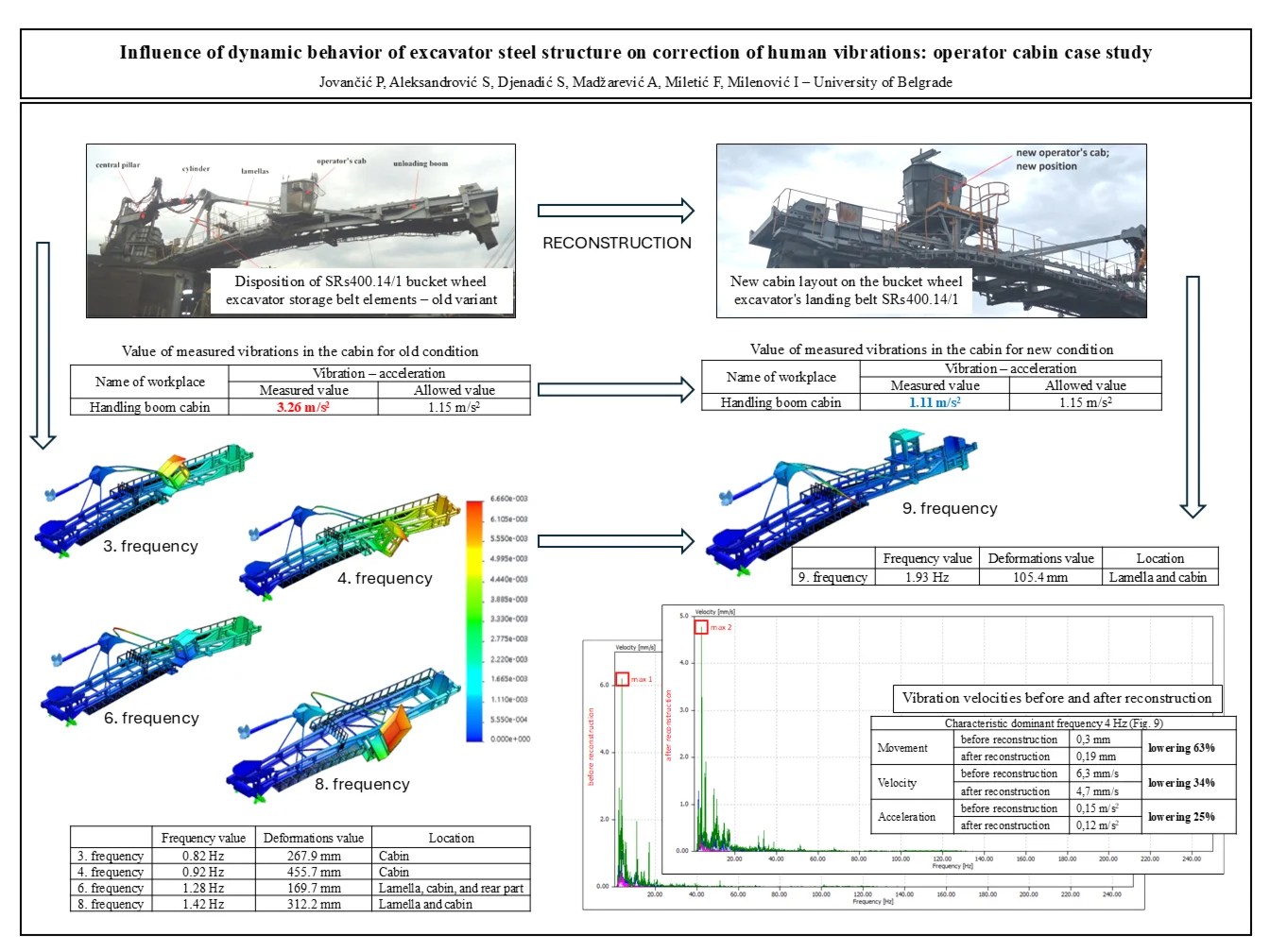
The problem was the increased human vibrations on the cab of the excavator boom operator's cab. Inadequate cabin location caused an increase in vibration levels. The consequence is the poor health of the operator. The solution is the reconstruction or relocation of the cabin with the addition of a suitable base of a certain level of rigidity. In this case study, the first step was to determine the current state and behavior of the structural part, based on measurements and the existing design. After the reconstruction, the correctness of the redesign was proven, also after the measurements were performed. Also, human vibrations were measured in the cabin for the old condition, before the reconstruction. The obtained values indicated poor dynamic behavior of the operator's structure and cab. After that, an unloading boom new design was made with a new cabin location as the optimal solution. Human vibration measurements were performed again for the newly reconstructed structure, at the same loads and operating parameters as for the old system. Proof of the correct reconstruction procedure is the newly measured human vibrations on the excavator boom operator's cab.
The motive for writing this paper was the occurrence of occupational diseases of operators. At this workplace, a person is continuously exposed to vibrations during 8 hours of work. The increased level of vibrations (above the permissible) led to diseases of the spinal column and stomach aches. That was the main reason for the reconstruction of part of the excavator structure [1].
Several areas are important for a closer understanding of the idea of this paper. The first area, experimental and numerical examination of the structural dynamics of certain assemblies, i.e. validation of finite element models using the experimentally obtained result, is treated in the given papers [2-14]. Luczak et al. [2] gave selected results from the aspect of multidisciplinary and interdisciplinary research oriented for the experimental and numerical study of structural dynamics in the whole structure of the wind turbine blade. The main goal of the investigation performed was to validate the finite element model (FME) of the modified structure of the wind turbine blade part by the experimental results. Dai, Wang, and Bailey [3] in their work, gave details about the simulation methodology for achieving numerical stability and a true representation of detailed structural behavior, comparing the results of simulation and experiment on parts of the structure. Spranghers et al. [4] have limited their research to finite element simulations and experimental validation of structures under an open-air explosion. This paper investigates the advantages and accuracy of finite element simulation of a loaded thin aluminum plate by confirming using performed experiments. Giagopoulos et al. [5] in their paper proposed a computational framework for estimating fatigue damage in structural systems by integrating operational experimental measurements into a finite element model. The proposed method was applied in the steel substructure of the lignite mill assembly in the power plant. The finite element model has been updated to match the dynamic characteristics measured in real operating conditions using measured vibrations from a limited number of sensors. Jovančić et al. [6] in this paper have defined the finite element method as a diagnostic tool to prevent anomalies during the operation of a bucket wheel excavator. Ribeiro et al. [7] in this paper describe the experimental calibration of a three-dimensional numerical model of a vehicle structure based on modal parameters. The dynamic tests that were performed enabled the determination of frequencies and modal configurations of many vibration modes. Seventekidis et al. [8] have tested in their paper a new Structural Health Monitoring method where all data are derived exclusively through the finite element method. The proposed method can be especially applied in cases when certain types of damage are expected, or the anomalies are adequately defined so that they can be efficiently simulated using finite element models. Hadi Jalali et al. [9] in this paper gave a dynamic analysis of a high-speed rotor with certain geometric and mechanical properties using a 3D finite element model and an experimental modal test. A good agreement between theoretical and experimental results indicated the accuracy of the finite element model. Bošnjak et al. [10] have performed modeling with finite elements of excavator-tracked transport in this paper. The goal of the study presented in this paper was to diagnose the cause of the damage to the bucket wheel excavator crawler chain links. To identify the reasons behind chain link failures, stress state calculations were performed as well as experimental investigations which, given the nature of the failure, included visual and metallographic examinations, chemical composition analysis, and tests of mechanical properties. Rusinski et al. [11, 12] in these papers presents attempt to the process of the validation of the numerical model based on the experimental results. The Modal Assurance Criterion between the numerical and experimental model was selected as the indicating factor. Gnjatović et al. [13] gave a unique three-step method for identifying the FREM (frequency of revolutions of the bucket-wheel-drive electromotor) range, where the vibroactivity of the load-bearing structure is within the permissible limits. Validation of the spatial reduced dynamic model of the slewing superstructure and the corresponding mathematical model, as well as the overall approach to the determination of the dynamic response, were performed by the means of vibrodiagnostics under the real exploitation conditions. In his paper [14], Kashani and Hashemi presented an innovative approach to the finite element method (FEM) model and frequency-dependent dynamic finite elements (DFE). The effects of various combined axial loads and ultimate moments on the stiffness and fundamental frequencies of the structure were examined.
The second area, experimentally conducted measurements of vibrations on the structure and human vibrations on specific parts to define the current state and determine the trend of behavior, is treated in the given works [15-20]. Wu Ren et al. [15] To study the comfort of driving in a cabin with special equipment, they experimented with an impact hammer and observed signals using an acceleration sensor. According to the test results, the natural frequency was calculated and compared with the analysis of the results by the finite element method. The results showed that the vibrations of the cabin and the results of the finite elements agree well, but that the natural frequency of the cabin is close to the frequency of vibrations of the human body, which is unfavorable. Caffaro et al. [16] within their paper investigated whether the active cabin suspension system installed on the telescopic loader is effective in reducing vibrations and improving comfort. Damnjanović, Jovančić, and Aleksandrović [17] presented in the paper the results of vibration measurements at characteristic places on the drive of a belt conveyor of a bucket wheel excavator to find a weak point. Deboli, Calvo, and Preti [18] in this paper describe the transmissibility of tractor seat vibrations. The tests were performed on a tractor operating on different surfaces and in different configurations. Transmissibility of seats in three directions was acquired. The results suggest that the tractor manufacturer should consider both movement and rolling when designing the machine, as they affect seat acceleration. Jooseon Oh et al. [19] in this paper evaluated the vibrations while driving the tractor in different conditions according to the type of cabin suspension and determined the effects of different methods of supporting the cabin for these vibrations. Driving vibrations on flat and uneven roads were measured using four tractors equipped with different types of cabin suspension and human vibrations were analyzed based on ISO 2631-1. Goyal and Pabla [20] presented in their paper an overview of the latest vibration monitoring methods and signal processing techniques for Structural Health Monitoring in manufacturing operations. These methods and techniques are used as tools to collect, visualize, and analyze sampled data collected in any processing operation that can then be used to make decisions about maintenance strategies.
The third area, structural monitoring of the condition and continuous monitoring of the structure under different workloads to detect damage and determine the current health of the structure was covered by the works [21-29]. Structural Health Monitoring relies on continuous observation of the dynamic system over some time, to observe and identify its actual state but also behavior over time, to reveal behaviors that go beyond the nominal framework. Therefore, future conditions can be predicted. Cawley [21] in his article, divides Structural Health Monitoring into four broad categories: monitoring the condition of rotating machines, global monitoring of large structures (identification of structures), monitoring a large area where the covered area is part of a larger structure, and local monitoring. These issues are discussed, and ways forward are proposed; it is concluded that given better-focused research and development considering the key factors identified here, Structural Health Monitoring has the potential to follow the path of rotating machine condition monitoring and become a widely deployed technology. Ye Xiao-Wei, Dong, and Tan Liu [22] in their paper dealt with surveillance systems based on technology based on machine vision as part of Structural Health Monitoring. The purpose of this review article is devoted to presenting a summary of the basic theories and practical applications of the machine vision-based technology employed in structural monitoring as well as its systematic error sources and integration with other modern sensing techniques. Dong and Catbas [23] presented in their paper a general overview of the concepts, approaches, and actual practices of Structural Health Monitoring, together with relevant literature that is rapidly accumulating. Local monitoring includes applications such as crack detection, evaporation, delamination, rust, and loose bolts. Globally, applications include displacement measurement, structural behavior analysis, vibration usability, modal identification, model updating, damage detection, cable force monitoring, load factor estimation, and structural identification using input-output information. Silva et al. [24] in this paper defined Structural Health Monitoring that relies on continuous observation of a dynamic system over time to identify its actual state, detect abnormal behaviors, and predict future states. In this article, a new paradigm based on deep principal component analysis, rooted in the deep learning field, is presented to overcome these limitations. The proposed technique is validated through the application of a progressively damaged prestressed concrete bridge and a three-span suspension bridge. Xunxun et al. [25] presented an investigation of the dynamic behavior of a rotor coil considering flexible coupling and frequency dependence. Based on simulation and measurement data, it was determined that the rotor coil smoothly passes through the critical rotor speed point. Jamadin et al. [26] established the relationship between vibration and dynamic loading, using finite element (FE) model analysis for verification and improvement. A relationship was established between structural stiffness and natural frequency under different conditions. Saidin et al. [27] defined vibration sensing and modal identification for assessing the “health” of bridge structures. Advanced concepts and applications related to safety assessment methods, including damage detection and load-bearing capacity, were analyzed. Ghazali and Rahiman [28] reviewed the latest vibration analysis for equipment monitoring and diagnosis, including data acquisition, feature extraction, and fault recognition techniques using artificial intelligence. Chu et al. [29] reviewed the fundamentals of vibration analysis. A potential application is fault detection in electric submersible pump systems in the petroleum industry.
The comparative advantage of this paper compared to all other works is that it established the dependence between the global dynamic behavior of the boom and the operator's cabin with the human vibrations to which the operator is exposed. Reconstruction of the operator's cabin (relocating the cabin and adding lamellas) raised the stiffness level of the boom, i.e. increased the first frequency of the structure. As a result, human vibrations have been reduced, that is, occupational diseases of operators have been eliminated. Most of the papers were based on the application of the finite element method in solving structural problems. For the first time, direct dependence was established between the dynamic behavior of the excavator boom structure and human health.
2. Conceptual setting of the methodological approach
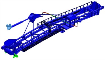
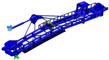
During excavator operation, impermissibly high oscillations of the boom occur. This creates very unfavorable conditions for the conveyor operator at the operating console. Manifestations of this are measured by increased vibration accelerations at a characteristic location in the landing boom operator’s cabin. Fig. 1 shows the disposition of these elements.
Fig. 1Disposition of SRs400.14/1 bucket wheel excavator storage belt elements – old variant
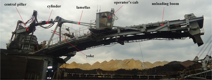
The excavator has an asymmetrically placed cabin of the landing boom operator about the axis of the handling conveyor – the cabin is located on the side of the conveyor. Due to this, in the process of exploitation, there was often a very bad dynamic behavior of the landing boom, where the amplitudes of oscillations reached over 500 mm, and in some cases over 600 mm. This can only have negative repercussions on the boom operator's cabin. By solving the cabin problem, the global problem of inadequate landing boom behavior but also the global dynamic behavior of the excavator is solved. This can extend the service life of the machine.
In such versions with one pair of lamellas, the deformation of the beam between the articulated support and the yoke is very pronounced. Besides, additional deformation of the left beam overhang is also caused by the operator's cabin being positioned laterally about the conveyor axis. The bending moment of the beam is relatively large in the place with the yoke, while the energy of deformation of the beam is dominant throughout the whole boom. These are all parameters that have an extremely negative effect on the previous negative condition and behavior of the operator’s cabin of the landing boom. This is one of the reasons why the landing boom operator’s cabin needs to be reconstructed. As is well known, dynamic calculation is defined by free undamped oscillations. The first few forms of oscillation are the most important to consider (they range up to 3 Hz). This is important because there is a lamella bearing near the operator’s cabin, which is a very elastic system that puts an additional dynamic load on the beam, which has a much higher level of stiffness/strength. This effect will be less if the cabin is moved into the boom axis and if another pair of lamellas is introduced. Therefore, in this case, the first step towards defining better behavior of this system is the relocation or reconstruction of the cabin of the operator of the handling belt, from the current lateral position to the position of the conveyor axis. The presence of the operator's cabin always hurts the dynamic behavior of the landing boom, especially if it is positioned laterally about the conveyor axis and if it is level with a steel rope. Thus, the location of the landing boom operator's cabin has a direct impact on the behavior of the structure. Monitoring of condition and behavior, in addition to the measured human vibrations in the operator’s cabin, is carried out by modeling using the finite element method.
The main goal of this paper in solving the Structural Health Monitoring of the operator’s cabin is in the monitoring of human vibrations (accelerations) in the operator’s cabin during various operating parameters of the excavator excavation process. Solving the problem of the unloading boom operator’s cabin by measuring human vibration (acceleration) is performed according to the standards ISO 2631-1:1997(E) [30], ISO 5349-1:2001(E) [31]. This problem is the local structural behavior of the construction part. However, the global dynamic behavior of the unloading boom structure has a large influence on the local behavior of the cabin. Therefore, diagnostic identification of dynamic behavior was performed using the finite element method, with the first intrinsic characteristic frequencies obtained. At the same time, the acceleration (vibration) in the operator's cabin was measured, which was a consequence of the dynamic behavior of the unloading boom structure.
The reason for the reconstruction or relocation of the operator's cabin of the landing boom on the excavator is that the working conditions of the operator are significantly more difficult than prescribed by certain norms. The measured level of vibrations to which the worker is exposed while sitting in the cabin during the operation of the excavator is much higher than the allowed values [30, 31]. The daily limit value of exposure of the whole body of workers to vibrations is defined concerning the time of exposure of workers for 8 hours. So, the state of human vibrations was monitored during this period.
The measuring device used for measurement is a vibration analyzer [32]. Measurements were performed under strictly defined parameters of excavation: cut height 5.5 m, cut thickness 0.35 m, cut width 0.30 m. The excavator worked on digging coal, that is, in a hard-working environment. Table 1 shows the measured value of vibration parameters after 8 hours of monitoring on the SRs400.14/1 excavator. The measured value represents the average of the maximum values during 8 hours of effective excavator operation.
Table 1Value of measured vibrations in the landing boom operator's cabin for old condition
Name of workplace | Vibration – acceleration | |
Measured value | Allowed value | |
Handling boom cabin | 3.26 m/s2 | 1.15 m/s2 |
Proper reconstruction, which proceeded in several directions (the new location of the cabin shifted in the axis of the conveyor, installation of a more massive carrier/base of the cabin and adding a new pair of lamellas on the unloading boom), had a fundamental positive impact on the local behavior of the operator's cabin structure.
In Europe, the Vibration Directive (Directive 2002/44/EC) has been introduced to set minimum standards for controlling the risks, both from hand-arm and whole-body vibration [33]. The directive sets action values, above which it requires employers to control the vibration risks, and limit values, above which workers must not be exposed. For whole-body vibrations, these values are:
1) A daily exposure action value of 0.5 m/s2 (or, at the choice of the individual EU Member State, a vibration dose value of 9.1 m/s1.75),
2) A daily exposure limit value of 1.15 m/s2 (or, at the choice of the individual EU Member State, a vibration dose value of 21 m/s1.75) [32-33].
Based on the frequency-weighted acceleration signals, the daily vibration exposure is determined by calculating the exposure for each of the three axes separately and then selecting the highest of the three values. This necessitates an additional factor, , that must be applied to the measured vibration values. For the - and -directions the factor is 1.4. For the -direction, the factor is 1.0 [32]:
where is the reference duration of 8 hours and is an estimate of the time that the tool operators are exposed to the vibration or the duration of the entire operation including breaks [30], [33]. If a person is exposed to more than one source of vibration, a partial vibration exposure for each operation is to be calculated.
The maximum of these three values will then be the daily vibration exposure:
The good behavior of the structure in exploitation is based on as far as possible dynamic response from the excitation, the higher the first frequency and the greater the distance between the frequencies, the smaller the dynamic gain factor. Dynamic calculation includes the determination of free oscillations, forced oscillations, and distribution of kinetic and potential energy. The worst behavior of the structure is expressed by the first form of oscillation. Construction has good dynamic behavior if: the first frequency is high and if the gap between the frequencies is large. This can be achieved if the structure is made with maximum rigidity and minimum mass. The natural frequency is proportional, where k is element stiffness, and m is element mass. The solution of forced damped oscillations in the frequency domain is represented by the frequency characteristics of the supporting structure [34].
The problem with bucket wheel excavators is related to improper design of the structure geometry and an inadequately close relationship between the excitation frequencies and the response of the components. The aim should be to achieve good structural behavior in operation, i.e. a later dynamic response to any excitation, a higher first frequency and a greater distance between frequencies. The stress state of a structure depends on the geometry of the supporting structure (arrangement and dimensions of the main components), loads and load capacity, so this approach is justified. Dynamic calculation includes the determination of free oscillations, forced oscillations, and the distribution of kinetic and potential energy. All values included in the dynamic calculation are a function of time.
It is important to determine distribution of a difference between kinetic and potential energy on main shapes of oscillations [30]. Basic dynamical equation for dampened oscillations is:
where: – mass matrix, – damping matrix, – stiffness matrix of structure, , , – acceleration, velocity and deformation, – dynamic load vector, – time.
Kinetic and potential energy ( and ) of a finite element and a complete structure on -th oscillating shape are:
where: is -th own frequency, is -th own vector and is corresponding -th own vector of the component.
The manifestation of energy consumption in the oscillation system is the level of vibration, i.e. the size of the amplitude. The amplitude is affected by mass, damping and stiffness, which is shown by the differential Eq. (3).
The amplitude is an indicator of the intensity of the disturbance force. The mechanical state changes with the change in vibration amplitude. The most common case is that the change of state is in the direction of increasing amplitude. The amplitude of excitation depends on two factors:
where, – magnitude of the excitation (disturbance) force, – stiffness of a mechanical system.
In the case of a excavator, the magnitude of the excitation force is constant. Only by reducing the stiffness of the mechanical system can the magnitude of the amplitude be reduced. Stiffness is changed by changing the geometry of the structure and the method of support. By redistributing the mass (changing the position of the cabin) on the unloading boom of the excavator, as well as by introducing new lamellas for suspending the boom, the rigidity of the construction part is increased. Therefore, the first response frequency is higher, which automatically has an impact on the optimization of human vibrations in the cabin. The proposed new construction scheme has advantages over the existing one in several aspects: better machine operation, better visibility of the process, less impact on the operator's health, and extension of the life of the construction part. This is the main goal of this work.
The basic idea of this paper is to increase the first natural frequency of a given structure by reconstructing the local part of the structure, which would reduce the human vibrations of the unloading boom cabin.
3. Results and discussion
Finite element analysis (FME) is a universal method that is used to solve problems in the design of new structures but also the post-design of existing structures (diagnosing and solving problems in operation) [35, 36]. In this paper, computer modeling and dynamic calculation by the numerical method FME, which is the basis of structural diagnostics, are performed. The excavator landing boom was modeled for the existing condition and the proposed new condition. Based on the dynamic model, the first few natural frequencies are defined, which best characterize the dynamic behavior of the excavator.
3.1. Model of the landing boom – existing condition
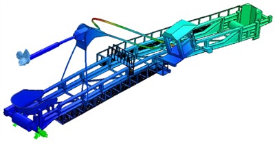
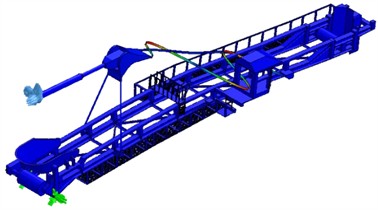
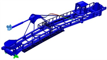
Fig. 2 shows a model of a landing boom according to the existing condition (the operator’s cabin is placed sideways about the boom structure).
For the existing condition of the landing boom, a dynamic model (modal analysis) was performed, where the first ten natural frequencies were defined, which more closely determined the dynamic state of the complete structure. Fig. 3 shows the first ten natural frequencies and their basic characteristics of deformations.
Table 2Characteristic frequencies and deformations of the landing boom for the old condition
Ordinal number of natural frequency | Frequency value | Deformations value | Location |
3. frequency | 0.82 Hz | 267.9 mm | Cabin |
4. frequency | 0.92 Hz | 455.7 mm | Cabin |
6. frequency | 1.28 Hz | 169.7 mm | Lamella, cabin, and rear part |
8. frequency | 1.42 Hz | 312.2 mm | Lamella and cabin |
The characteristic frequencies that are directly related to the boom operator’s cabin are given in Table 2.
Fig. 2Model of the landing boom – existing condition, cabin positioned sideways
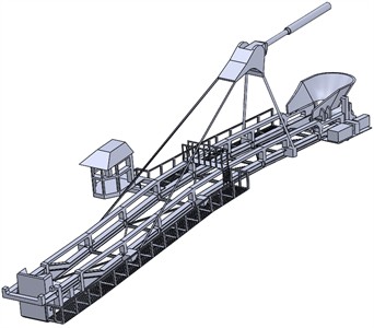
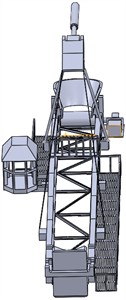
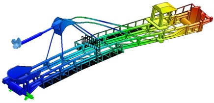
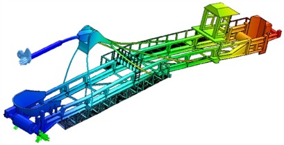
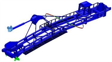
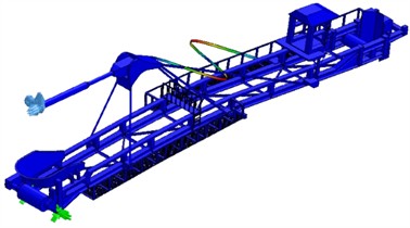
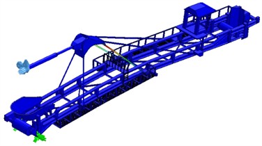
Fig. 3The first 10 natural frequencies of the existing landing boom model
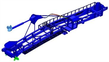
a) The frequency of the landing boom structure for the existing condition is 0.46 Hz, and lamella displacement is 13.5 mm
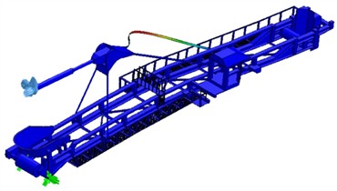
b) The frequency of the landing boom structure for the existing condition is 0.47 Hz, and lamella displacement is 15.8 mm
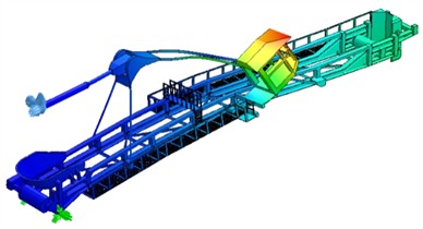
c) The frequency of the landing boom structure for the existing condition is 0.82 Hz, and cabin displacement is 267.9 mm
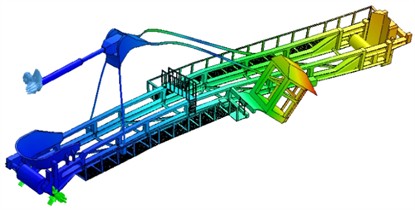
d) The frequency of the landing boom structure for the existing condition is 0.92 Hz, and cabin displacement is 455.7 mm
e) The frequency of the landing boom structure for the existing condition is 1.23 Hz, and lamella displacement is 14.5 mm
f) The frequency of the landing boom structure for the existing condition is 1.28 Hz, and deformation is 169.7 mm – displacement of lamella, cabin and the rear part of the boom structure
g) The frequency of the landing boom structure for the existing condition is 1.30 Hz, and lamella displacement is 16.5 mm
h) The frequency of the landing boom structure for the existing condition is 1.42 Hz, and displacement of lamella and cabin is 312.2 mm
i) The frequency of the landing boom structure for the existing condition is 2.38 Hz, and lamella displacement is 15.3 mm
j) The frequency of the landing boom structure for the existing condition is 2.50 Hz, and lamella displacement is 24.4 mm
3.2. Model of the landing boom – new condition
The main intention of the reconstruction is to move the existing operator’s cabin into the conveyor axis (use of the existing cabin construction), to raise the cabin about the flow of material going in the belt to the allowed, optimal distance, cabin displacement towards the overflow location (two reasons: better overflow location and possibility of optimal entry of the operator into the cabin), as well as the introduction of a hydraulic system for leveling the cabin. The conceptual solution is given in Fig. 4.
Fig. 4Old and new location of the landing boom operator’s cabin
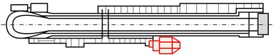
a) Old location
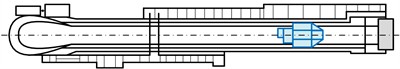
b) New location
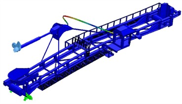
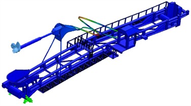
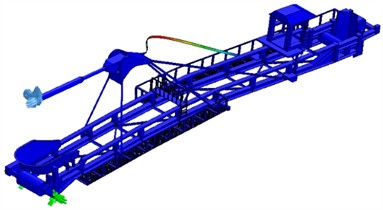
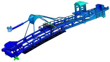
Fig. 5 shows a model of the landing boom with the cabin moved to the axis of the landing boom (belt) and a new supporting structure (operator’s cabin mounted in the axis of the landing boom) but with another pair of lamellas added.
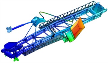
For the new model, a new pair of lamellas and a cabin placed in the axis of the boom were introduced, and a dynamic model was made, where the first ten natural frequencies were defined, which more closely determined the dynamic state of the structure. Fig. 6 shows the first ten natural frequencies and their basic characteristics of deformations.
The characteristic frequency that directly refers to the cabin of the landing boom operator is 9. frequency 4.93 Hz, deformation 105.4 mm – displacement of the lamellas (most of it) and displacement of the upper part of the cabin. Table 3 shows the characteristic deformation frequencies according to which the cabin of the handling belt operator behaves.
Fig. 5Model of the landing boom – introduced a new pair of lamellas, a cabin mounted in the axis of the boom
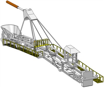
Fig. 6The first 10 natural frequencies of the existing landing boom model and a new pair of lamellas introduced, the cabin mounted in the boom axis moved towards the overflow
a) Frequency of the landing boom structure is 0,46 Hz, and deformation is 13.5 mm – lamella displacement
b) Frequency of the landing boom structure is 0.48 Hz, and deformation is 15.7 mm – lamella displacement
c) Frequency of the landing boom structure is 0,82 Hz, and deformation is 427.1 mm – bending of the whole boom and lamellas
d) Frequency of the landing boom structure is 1.10 Hz, and deformation is 422.4 mm – bending of the whole boom and lamellas
e) Frequency of the landing boom structure is 4.24 Hz, and deformation is 14.5 mm – lamella displacement
f) Frequency of the landing boom structure is 4.31 Hz, and deformation is 16.3 mm – lamella displacement
g) Frequency of the landing boom structure is 4.76 Hz, and deformation is 14.5 mm – lamella displacement
h) Frequency of the landing boom structure is 4.76 Hz, and deformation is 14.4 mm – lamella displacement
i) Frequency of the landing boom structure is 4.93 Hz, and deformation is 105.4 mm – lamella displacement and the upper part of the cabin
j) Frequency of the landing boom structure is 2.38 Hz, and deformation is 15.3 mm – lamella displacement
Table 3Characteristic frequencies of the landing boom operator’s cabin
Old model – existing condition and cabin sideways | |||
Ordinal number of natural frequency | Frequency value | Deformations value | Location |
3. frequency | 0.82 Hz | 267.9 mm | Cabin |
4. frequency | 0.92 Hz | 455.7 mm | Cabin |
6. frequency | 1.28 Hz | 169.7 mm | Lamella, cabin, and rear part |
8. frequency | 1.42 Hz | 312.2 mm | Lamella and cabin |
New model – added a pair of lamellas and a cabin in the axis | |||
Ordinal number of natural frequency | Frequency value | Deformations value | Location |
9. frequency | 1.93 Hz | 105.4 mm | Lamella and the upper part of the cabin |
From the values obtained from Table 3, it can be unequivocally concluded that the highest global strength is related to the new model. The worst possible behavior of the discharge boom is an existing condition. With this dynamic calculation, it has proven to be the current optimal solution. By introducing an added pair of lamellas (new model) and moving the cabin into the boom axis, the boom stiffness level is raised even higher, i.e. the cabin's natural frequency would increase with the least possible deformation/displacement of this part of the landing boom structure. Observing the global behavior of the entire structure of the landing boom, the highest frequencies are related to the new model (the model with the highest rigidity), i.e. the smallest deformations of the end of the landing boom. All these deformations related to the global behavior of the landing boom are directly related to the digging process, in the largest percentage. Other moving elements have a much smaller significance in the behavior of the landing boom. Therefore, in any analyzed case, the optimization of the position of the operator's cabin of the landing mast in the axis of the boom and moved towards the overflow, is the best possible solution that affects the favorable dynamic behavior of both the boom itself and the operator’s cabin. Fig. 7 shows the optimal relationship between minimum displacement and maximum frequency.
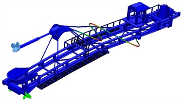
Fig. 8 shows the new layout of the cabin on the bucket wheel excavator landing boom and the new design of the cabin support (the support has a high level of strength).
Fig. 7Optimal relationship between minimum displacement and maximum frequency
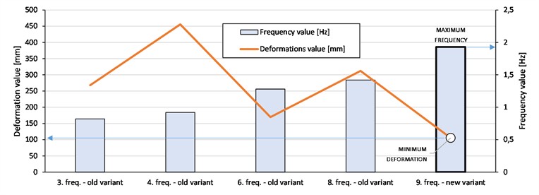
Fig. 8New cabin layout on the bucket wheel excavator's landing belt SRs400.14/1
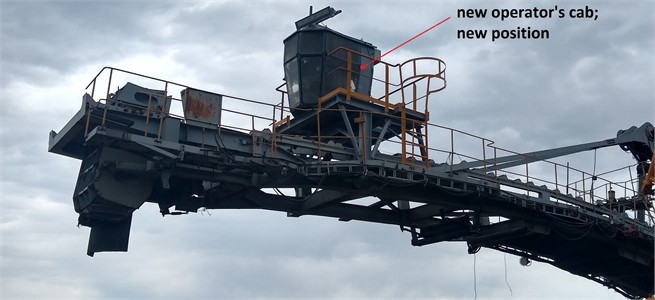
Table 4 shows the subsequently measured values of vibration parameters on the SRs400.14/1 excavator. The obtained value is less than the allowed value, which was the goal of the reconstruction and extension of the service life of the part of the structure.
Table 4Value of measured vibrations in the landing boom operator’s cabin for new condition
Name of workplace | Vibration – acceleration | |
Measured value | Allowed value | |
Landing boom cabin | 1.11 m/s2 | 1.15 m/s2 |
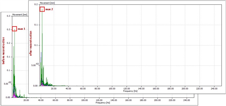
To verify the effectiveness of the reconstruction, vibration measurements were conducted after reconstruction and compared to the previous measurement. The measurement was performed on the conveyor structure (next to the conveyor drive) in all three directions: vertical (shown on the diagram in green), horizontal (shown in blue) and axial (shown in red). Fig. 9 shows comparative diagrams for movement, velocity and acceleration in the frequency domain, before and after the reconstruction. Vertical vibrations are pronounced. Vibrations are given as proof of model correctness.
Table 5 shows the measured values of vibrations on the conveyor structure. The reduction of vertical dominant vibrations after reconstruction is evident.
Fig. 9Diagrams of the measured vibrations before and after the cabin reconstruction
a) Movement before and after reconstruction
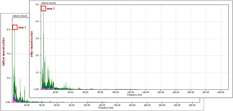
b) Vibration velocities before and after reconstruction
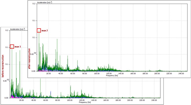
c) Vibration acceleration before and after the reconstruction
Table 5Vibration values on the structure before and after reconstruction
Characteristic dominant frequency 4 Hz (Fig. 9) | |||
Movement | Before reconstruction | 0.3 mm | Lowering 63 % |
After reconstruction | 0.19 mm | ||
Velocity | Before reconstruction | 6.3 mm/s | Lowering 34 % |
After reconstruction | 4.7 mm/s | ||
Acceleration | Before reconstruction | 0.15 m/s2 | Lowering 25 % |
After reconstruction | 0.12 m/s2 | ||
4. Conclusions
Human vibration monitoring was performed at the new position of the cabin of the landing boom during 8 effective hours of operation as proof of well-conducted diagnostics by numerical means. The validation of modeling for Structural Health Monitoring was confirmed through the re-measurement of human vibrations. The measurement was performed with the same vibration analyzer, under the same operating parameters as when measuring with the old layout of the cabin elements. The measured human vibrations after the reconstruction are 1.11 m/s2, which is less than the limit value of 1.15 m/s2. The initial value of these vibrations, before the reconstruction, was 3.26 m/s2, which was 2.8 times higher than the permitted values. The mass of the cabin has increased from 1300 kg to 2020 kg. This led to an increase in the level of stiffness and spatial solidity of the cabin, and thus to a decrease in acceleration. By influencing the global behavior of the unloading boom and cabin, there was a positive response of the local part of the structure of the new cabin.
The starting hypothesis is that by reconstructing the local part of the structure (by moving the cabin and adding a new supporting structure), its first natural frequency is increased, which would reduce the human vibrations of the unloading boom cabin (optimal work of the operator). Experimental and numerical testing of the structural dynamics of the unloading boom of the excavator, i.e. validation of the finite element model, was performed. Then, measurements of human vibrations were performed on the cabin of the unloading boom to define the current condition and determine the trend of behavior, in a certain time interval. Acceleration measurements were also performed on the part of the conveyor structure near the drive. The measurement was made before and after the reconstruction. Movement is reduced by 63 %, velocity by 34 % and acceleration by 25 %. It is proof that the reconstruction of the cabin and unloading boom was well done.
Structural monitoring of the condition and continuous monitoring of the structure were performed to detect irregularities in the work and to determine the current Structural Health Monitoring. Proof of the correctness of the methodological approach is the reconstruction and relocation of the cabin to a new location. Performed measurements of human vibrations after reconstruction confirmed this.
The proposed solution (new location of the cabin and installation of new lamellas) is considered optimal for the current state and behavior of the part of the unloading boom structure. A better solution would be to automatically monitor and manage the process, without human crew. In that case, the cabin would not exist, only the new lamellas would remain. There would be no humane vibrations. To comply with the sufficient stiffness of the unloading boom (new mass analysis), the calculation should be done again to raise the first frequency, i.e. define a new geometry.
References
-
“Relocation of the operator’s cabin of lane 2, Excavator SRs400,” (in Serbian), Joint Stock Company Electrical Industry Belgrade – Branch TE-KO Kostolac, 2020.
-
M. Luczak, S. Manzato, B. Peeters, K. Branner, P. Berring, and M. Kahsin, “Updating finite element model of a wind turbine blade section using experimental modal analysis results,” Shock and Vibration, Vol. 2014, pp. 1–12, Jan. 2014, https://doi.org/10.1155/2014/684786
-
X. H. Dai, Y. C. Wang, and C. G. Bailey, “Numerical modelling of structural fire behaviour of restrained steel beam-column assemblies using typical joint types,” Engineering Structures, Vol. 32, No. 8, pp. 2337–2351, Aug. 2010, https://doi.org/10.1016/j.engstruct.2010.04.009
-
K. Spranghers, I. Vasilakos, D. Lecompte, H. Sol, and J. Vantomme, “Numerical simulation and experimental validation of the dynamic response of aluminum plates under free air explosions,” International Journal of Impact Engineering, Vol. 54, pp. 83–95, Apr. 2013, https://doi.org/10.1016/j.ijimpeng.2012.10.014
-
D. Giagopoulos, A. Arailopoulos, V. Dertimanis, C. Papadimitriou, E. Chatzi, and K. Grompanopoulos, “Structural health monitoring and fatigue damage estimation using vibration measurements and finite element model updating,” Structural Health Monitoring, Vol. 18, No. 4, pp. 1189–1206, Aug. 2018, https://doi.org/10.1177/1475921718790188
-
P. D. Jovančić, D. Ignjatović, M. Tanasijević, and T. Maneski, “Load-bearing steel structure diagnostics on bucket wheel excavator, for the purpose of failure prevention,” Engineering Failure Analysis, Vol. 18, No. 4, pp. 1203–1211, Jun. 2011, https://doi.org/10.1016/j.engfailanal.2011.03.001
-
D. Ribeiro, R. Calçada, R. Delgado, M. Brehm, and V. Zabel, “Finite-element model calibration of a railway vehicle based on experimental modal parameters,” Vehicle System Dynamics, Vol. 51, No. 6, pp. 821–856, Jun. 2013, https://doi.org/10.1080/00423114.2013.778416
-
P. Seventekidis, D. Giagopoulos, A. Arailopoulos, and O. Markogiannaki, “Structural health monitoring using deep learning with optimal finite element model generated data,” Mechanical Systems and Signal Processing, Vol. 145, p. 106972, Nov. 2020, https://doi.org/10.1016/j.ymssp.2020.106972
-
M. H. Jalali, M. Ghayour, S. Ziaei-Rad, and B. Shahriari, “Dynamic analysis of a high speed rotor-bearing system,” Measurement, Vol. 53, pp. 1–9, Jul. 2014, https://doi.org/10.1016/j.measurement.2014.03.010
-
S. M. Bošnjak, D. B. Momčilović, Z. D. Petković, M. P. Pantelić, and N. B. Gnjatović, “Failure investigation of the bucket wheel excavator crawler chain link,” Engineering Failure Analysis, Vol. 35, pp. 462–469, Dec. 2013, https://doi.org/10.1016/j.engfailanal.2013.04.025
-
E. Rusiński, J. Czmochowski, P. Moczko, and D. Pietrusiak, “Numerical modeling and experimental measurements of the bucket wheel excavator at operational load,” in 11th International Conference on Vibration Problems (ICOVP-2013), 2013.
-
E. Rusiński, J. Czmochowski, P. Moczko, and D. Pietrusiak, “Assessment of the correlation between the numerical and experimental dynamic characteristics of the bucket wheel excavator in terms of the operational conditions,” FME Transactions, Vol. 2013, No. 41, pp. 298–304, 2013.
-
N. Gnjatović, S. Bošnjak, and A. Stefanović, “Analysis of the dynamic response as a basis for the efficient protection of large structure health using controllable frequency-controlled drives,” Mathematics, Vol. 11, No. 1, p. 154, Dec. 2022, https://doi.org/10.3390/math11010154
-
M. Kashani and S. M. Hashemi, “Dynamic finite element modelling and vibration analysis of prestressed layered bending-torsion coupled beams,” Applied Mechanics, Vol. 3, No. 1, pp. 103–120, Jan. 2022, https://doi.org/10.3390/applmech3010007
-
W. Ren, B. Peng, J. Shen, Y. Li, and Y. Yu, “Study on vibration characteristics and human riding comfort of a special equipment cab,” Journal of Sensors, Vol. 2018, pp. 1–8, Jan. 2018, https://doi.org/10.1155/2018/7140610
-
F. Caffaro, M. M. Cremasco, C. Preti, and E. Cavallo, “Ergonomic analysis of the effects of a telehandler’s active suspended cab on whole body vibration level and operator comfort,” International Journal of Industrial Ergonomics, Vol. 53, pp. 19–26, May 2016, https://doi.org/10.1016/j.ergon.2015.10.009
-
V. Damnjanović, P. Jovančić, and S. Aleksandrović, “Extensive vibrations of the belt conveyor drive electromotor of a bucket wheel excavator as a result of intensified wear-and-tear of its mount support,” Journal of Vibroengineering, Vol. 19, No. 1, pp. 214–222, Feb. 2017, https://doi.org/10.21595/jve.2016.17321
-
R. Deboli, A. Calvo, and C. Preti, “Whole-body vibration: Measurement of horizontal and vertical transmissibility of an agricultural tractor seat,” International Journal of Industrial Ergonomics, Vol. 58, pp. 69–78, Mar. 2017, https://doi.org/10.1016/j.ergon.2017.02.002
-
J. Oh, W.-J. Chung, H.-W. Han, J.-T. Kim, G.-H. Son, and Y.-J. Park, “Evaluation of tractor ride vibrations by cab suspension system,” Transactions of the ASABE, Vol. 63, No. 5, pp. 1465–1476, Jan. 2020, https://doi.org/10.13031/trans.13795
-
D. Goyal and B. S. Pabla, “The vibration monitoring methods and signal processing techniques for structural health monitoring: a review,” Archives of Computational Methods in Engineering, Vol. 23, No. 4, pp. 585–594, Mar. 2015, https://doi.org/10.1007/s11831-015-9145-0
-
P. Cawley, “Structural health monitoring: Closing the gap between research and industrial deployment,” Structural Health Monitoring, Vol. 17, No. 5, pp. 1225–1244, Jan. 2018, https://doi.org/10.1177/1475921717750047
-
X. W. Ye, C. Z. Dong, and T. Liu, “A review of machine vision-based structural health monitoring: methodologies and applications,” Journal of Sensors, Vol. 2016, pp. 1–10, Jan. 2016, https://doi.org/10.1155/2016/7103039
-
C.-Z. Dong and F. N. Catbas, “A review of computer vision-based structural health monitoring at local and global levels,” Structural Health Monitoring, Vol. 20, No. 2, pp. 692–743, Jul. 2020, https://doi.org/10.1177/1475921720935585
-
M. Silva, A. Santos, R. Santos, E. Figueiredo, C. Sales, and J. C. Costa, “Deep principal component analysis: An enhanced approach for structural damage identification,” Structural Health Monitoring, Vol. 18, No. 5-6, pp. 1444–1463, Sep. 2018, https://doi.org/10.1177/1475921718799070
-
X. Ma, S. Li, W. Tian, X. Qu, S. Wang, and Y. Wang, “Dynamic behavior analysis of the winding rotor with structural coupling and time-frequency varying parameters: simulation and measurement,” Applied Sciences, Vol. 11, No. 17, p. 8124, Sep. 2021, https://doi.org/10.3390/app11178124
-
A. Jamadin, S. Abdul Kudus, A. D. H. Ya’Akob, M. F. Misnan, and Z. Mohd Jaini, “Vibration-based finite element model analysis on dynamic characteristics of ultra-high performance concrete beam,” International Journal of Integrated Engineering, Vol. 15, No. 7, pp. 213–223, Dec. 2023, https://doi.org/10.30880/ijie.2023.15.07.020
-
S. S. Saidin, A. Jamadin, S. Abdul Kudus, N. Mohd Amin, and M. A. Anuar, “An overview: the application of vibration-based techniques in bridge structural health monitoring,” International Journal of Concrete Structures and Materials, Vol. 16, No. 1, Dec. 2022, https://doi.org/10.1186/s40069-022-00557-1
-
M. H. Mohd Ghazali and W. Rahiman, “Vibration analysis for machine monitoring and diagnosis: a systematic review,” Shock and Vibration, Vol. 2021, No. 1, pp. 1–25, Sep. 2021, https://doi.org/10.1155/2021/9469318
-
T. Chu, T. Nguyen, H. Yoo, and J. Wang, “A review of vibration analysis and its applications,” Heliyon, Vol. 10, No. 5, p. e26282, Mar. 2024, https://doi.org/10.1016/j.heliyon.2024.e26282
-
“Mechanical Vibration and Shock – Evaluation of Human Exposure to Whole-Body Vibration – Part 1: General requirements,” International Standard ISO 2631-1, 1997.
-
“Mechanical Vibration – Measurement and Evaluation of Human Exposure to Hand-Transmitted Vibration – Part 1: General requirements,” International Standard ISO 5349-1:2001(E), 2001.
-
“Technical Documentation: Human Vibration Analyzer Type 4447 (BE1772),” BRÜEL & KJÆR, Feb. 2009.
-
“Directive 2002/44/EC-vibration,” European Agency for Safety and Health at Work, 2002.
-
T. Maneski, “Monography computer modeling and structures calculation,” Serbia, Faculty of Mechanical Engineering, University of Belgrade, 1988.
-
N. Trišović, T. Maneski, and D. Kozak, “Developed procedure for dynamic reanalysis of structures,” Strojarstvo – Journal for Theory and Application in Mechanical Engineering, Vol. 52, No. 2, pp. 147–158, 2010.
-
N. S. Ottosen and H. Petersson, Introduction to the Finite Element Method. Prentice Hall Int., 1992.
About this article

This article is a contribution to project TR035040 funded by the Serbian Ministry of Education and Science.
The datasets generated during and/or analyzed during the current study are available from the corresponding author on reasonable request.
Predrag Jovančić: conceptualization, formal analysis. Snežana Aleksandrović: methodology, formal analysis. Stevan Djenadić: investigation, software. Aleksandar Madžarević: methodology, supervision. Filip Miletić: investigation, software.
The authors declare that they have no conflict of interest.
