Abstract
The synchronous condenser plays a crucial role in reactive power compensation and voltage support in ultra-high voltage direct current power grids. Vibration is a key bottleneck for the safe and stable operation of the synchronous condenser, especially rotor vibration resulting from electromagnetic torque caused by inter-turn short-circuit. This article takes a 300 MV large synchronous condenser as the research object, and studies the influence of electromagnetic torque caused by inter-turn short-circuit on the vibration of the rotor. Through theoretical analysis and finite element simulation, a theoretical model and a finite element model of rotor bending-torsional coupled vibration were established, and the accuracy of the theoretical model was validated experimentally. The results show that: The first three bending frequencies are 11.93 Hz, 31.27 Hz, and 89.46 Hz; Under both static and dynamic imbalance conditions, the vibration amplitude of the rotor increases with the increase of the shorted turn ratio; The vibration amplitude before and after being stimulated under dynamic unbalance is larger than that under static imbalance. The research results can provide a theoretical basis for the design and safe operation and maintenance of the synchronous condenser.
Highlights
- Establish a rotor bending torsional coupling vibration model through theoretical analysis.
- Verify the accuracy of the rotor bending torsional coupling vibration model through experiments.
- Construct a finite element model and analyze the bending torsional coupling vibration characteristics of the rotor.
1. Introduction
With the rapid development of high-voltage direct current transmission technology, the power grids present the characteristic of “strong direct-current and weak direct-current” [1], which may lead to insufficient dynamic reactive power reserve and grid voltage deterioration. The synchronous condenser, as a reactive power compensation device, has played an essential role in key issues such as dynamic reactive power reserve and insufficient voltage support at the transmission and reception ends of ultra-high voltage direct current in China in recent years [2-4]. At present, China’s new 300MVar synchronous condenser mainly includes QFT-300-2 air-cooled type and TTS-300-2 dual water-cooled type. So far, the State Grid System has successively put 43 large condensers in 19 stations into operation, with a total capacity of 12500Mvar. The safe and reliable operation of large-scale synchronous condensers is of great significance for improving the dynamic voltage stability of the power grid and ensuring the stability of high-voltage direct current transmission projects.
Previous literature has shown that large synchronous condenser units face severe vibration problems during commissioning and operation, such as unbalance [5], [6], oil film whirl [7], [8], double-frequency vibration [9], friction, inter-turn short-circuit [10]-[12], dynamic and static eccentricity [13], etc. The main reasons are: 1) Large synchronous condenser units have a considerable structural weight and size, and their working speed crosses the second-order critical state, resulting in complex vibration modes; 2) In operation, compared to generators, synchronous condensers can absorb reactive power and generate reactive power, with strong transient response and overload capabilities, and variable working conditions. These complex factors lead to prominent vibration and instability problems.
The excitation winding is the core component of rotating machinery such as synchronous condensers. The inter-turn short-circuit in the excitation winding and its induced vibration are among the most common faults in large synchronous condensers and generators [14]-[17]. The main causes of inter-turn short-circuit in high-speed synchronous condenser include unreasonable design of the rotor and stator structure, poor manufacturing process of the winding coils, damage or infiltration of metal particles during installation and maintenance, deformation and insulation damage under complex working conditions, winding aging caused by long-term operation, etc., which will lead to an increase in excitation current, a decrease in reactive power output, an increase in electromagnetic imbalance force and vibration deterioration. At the same time, it will also produce shaft voltage and direct-current magnetization, causing electrical corrosion of synchronous condenser components, magnetization of the main shaft, and even rotor grounding faults, triggering alarms and relay protection actions.
At the same time, inter-turn short-circuit can also cause significant electromagnetic torque [18], [19], which acts on the rotor and leads to abnormal rotor vibration. At present, this issue mainly focuses on generators. Reference [20] proposes a detection method for inter-turn short-circuit using changes in electromagnetic torque through finite element simulation of excitation winding inter-turn short-circuit faults in generators. S. Wan et al. [21] calculated and analyzed the electromagnetic torque under the short circuit of generator rotor, and obtained the average and instantaneous electromagnetic torque characteristics after the fault. W. Wang et al. [22] conducted theoretical and experimental research on the mechanism of inter-turn short-circuit between the stator and rotor of a 300Mvar synchronous condenser, and obtained the distribution of electromagnetic torque harmonic components under different faults. However, studies addressing vibration issues of synchronous condenser rotors caused by electromagnetic torque are still limited.
This article focuses on a large synchronous condenser unit and conducts theoretical research on the vibration of the rotor induced by electromagnetic torque under inter-turn short-circuit faults. It explores the influence of electromagnetic torque on the vibration of the rotor and the mechanism of bending torsional coupling vibration. Quantitative analysis of the influence of short-circuit turn ratio on rotor bending vibration, providing a theoretical reference for the safe and stable operation of rotating machinery such as large synchronous condenser units and steam turbine generators.
2. Theoretical analysis of bending torsional coupling vibration
2.1. Single disc rotor bending torsional coupling model
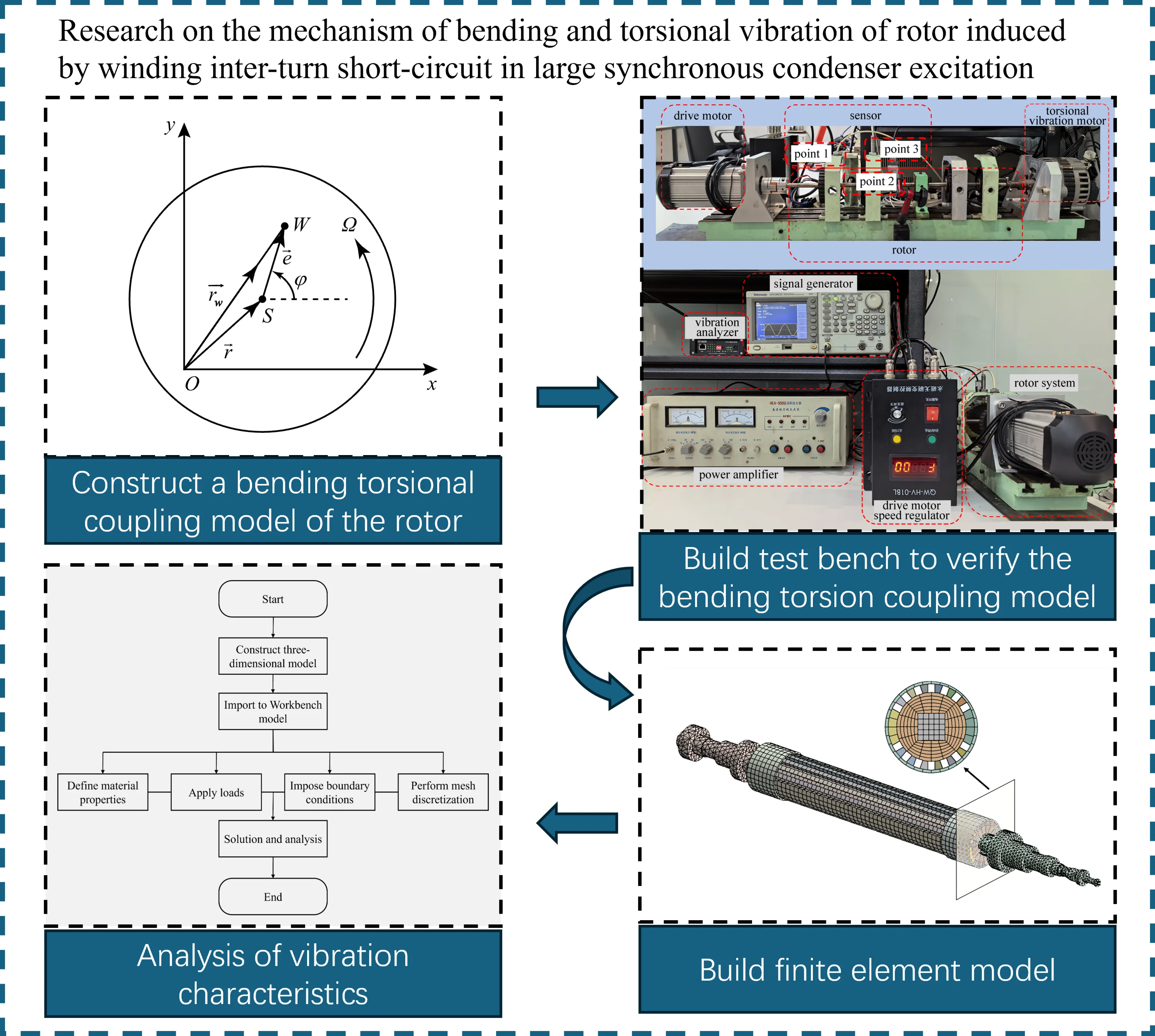
Taking a single-disc rotor model as the research object, where the disk position at time is shown in Fig. 1. The mass of the disc is , and the disc is mounted on a flexible, massless shaft with torsional compliance. The geometric center of the disc is point , whose coordinate is , and the mass center is point . The eccentricity is the distance between points and , and it is fixed relative to the axis. Point is the center of rotation, the distances to points and are and . The rotation speed of the disc is . At the initial moment ( 0), the phase angle of the eccentricity vector is . At time , the torsional angle of the disk is denoted as , and the angular displacement of relative to is defined as . Thus, Eq. (1) can be derived:
Fig. 1Schematic diagram of disc coordinates at time t
Record the coordinates of point , The system’s moment of inertia is , bending stiffness , bending vibration damping coefficient , torsional stiffness , torsional vibration damping coefficient , and the torque acting on the disc is . Establish a complex vector with the -axis as the real part and the -axis as the imaginary part.
The position vector at the geometric center , as shown in Eq. (2):
At point , the elastic restoring force and lateral damping force are given by Eq. (3) and (4):
At point , the gravity of the disc is given by Eq. (5):
The system kinetic energy is given by Eq. (6):
According to the Lagrange equation, as given in Eq. (7):
where, is the kinetic energy of the system; is the generalized coordinate of the system; is the generalized force corresponding to .
For the bending vibration of the disc, substituting Eq. (2)-(6) into Eq. (7) yields Eq. (8):
Simplify to obtain the differential equation of disc bending vibration, as shown in Eq. (9):
The inertia force term generated by the bending vibration of the rotor acting on point exerts a moment on point , as given in Eq. (10):
The disc gravity term on point exerts a moment on point , as given in Eq. (11):
Disc torsional recovery torque at point , as given in Eq. (12):
Torque of torsional damping of the disc at point , as given in Eq. (13):
The moment equilibrium equation about point is expressed by Eq. (14):
Simplify the differential equation of torsional vibration of the disc, as shown in Eq. (15):
In summary, when the disc undergoes both bending and torsional vibrations simultaneously, the unified mathematical model is expressed by Eq. (16) [23]:
2.2. Analysis of the influence of pulse torque on vibration based on the fourth-order Runge-Kutta method
Define , , , the mathematical model Eq (16) can be transformed into Eq. (17):
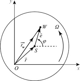
To verify the accuracy of this mathematical model, a bending torsional coupling test bench was set up. According to the rotor’s parameters: = 0.8 kg, = 0.00064 kg⋅m2. Calculate the stiffness and damping parameters based on the entire rotor system, = 3.5×10⁶ N/m, = 2 N·m/s, = 200 N/m, = 0.1 N·m/s. Based on the manufacturing accuracy level, obtain the eccentricity: = 0.03 m. Take the initial phase angle = 0, = 1500 rpm. Using the fourth-order Runge-Kutta method, analyze the influence of the pulse torque on the vibration of the rotor. The pulse torque applied is shown in Fig. 2, and the vibration amplitude in the -direction is shown in Fig. 3.
Fig. 2Applied pulse torque
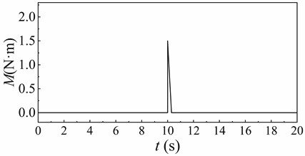
Fig. 3Theoretical vibration amplitude in x-direction

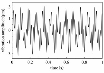
As illustrated in the figure, the peak-to-peak value increases from 241 μm to 272 μm following the application of an instantaneous torque. And subsequently gradually returns to a steady state, which aligns with theoretical expectations. This observation confirms that the mathematical model is validated as reasonable.
2.3. Design and verification of bending torsional coupling
2.3.1. Test bench design
Fig. 4(a) and (b) show the rotor bending-torsion coupling test bench. The test bench primarily consists of a signal generator, power amplifier, drive motor, drive motor speed regulator, torsional vibration motor, rotating shaft, disc, and vibration analyzer. The drive motor employs a DC shunt motor. The speed regulator adjusts and rectifies the 220 V AC power supply to provide current to the motor. By adjusting the speed regulator, stepless speed control within the range of 0 to 10,000 rpm can be achieved.
Fig. 4Bending torsional coupling test bench (These photographs were taken by the author Quan Jingzhou in Nanjing on September 10, 2025)

a) Physical diagram of rotor system
b) Physical diagram of control system
An alternating signal generated by the signal generator is amplified by the power amplifier and then supplied to the torsional vibration motor. This provides alternating current to the excitation winding of the torsional vibration motor, thereby generating torsional vibration. By controlling the amplitude and frequency of the output current, the amplitude and frequency of the torsional vibration can be regulated.
At measuring points 1 and 2, two eddy current sensors are used to collect bending vibration signals of the rotor in the and directions, which are then input into the vibration analyzer. At measuring point 3, an eddy current sensor is employed to acquire the torsional vibration signal, which is subsequently fed into the torsional vibration analyzer.
2.3.2. Bending torsional coupling vibration test
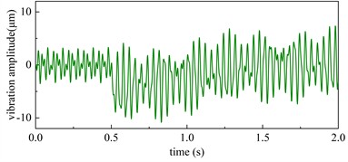
Fig. 5 presents the vibration waveforms and shaft center trajectories of the rotor under no torque excitation and transient torque excitation. Without torque excitation, the shaft center trajectory presents a high degree of coincidence. At the instant of transient torque excitation, the trajectory becomes disordered. Meanwhile, following the transient torque excitation, fluctuations are observed in the vibration waveform, with the peak-to-peak value increasing from 255 μm to 280 μm. The experiment indicates the presence of bending-torsion coupling phenomena in the rotor system, confirming the accuracy of the theoretical model.
Fig. 5Rotor vibration waveform and shaft center orbit diagram under different working conditions

a) No torque excitation

b) Torque excitation
Both simulation and experimental results indicate the presence of bending-torsion coupling phenomena in the rotor system. Under transient torque excitation, the vibration waveform of the rotor presents aperiodic behavior, and the shaft center trajectory exhibits disordered behavior. This leads to an instantaneous increase in vibration amplitude, resulting in vibrational instability.
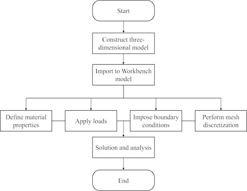
3. Condenser geometry and finite element analysis model
The geometric configuration and boundary conditions of the model investigated in this study are complex; therefore, employing the finite element method to discretize the continuous problem to obtain approximate numerical solutions [24], [25]. The research flow diagram is shown in Fig. 6.
Fig. 6Research process diagram
3.1. Geometric model
The synchronous compensator rotor investigated consists of a rotating shaft, rotor windings, damping system, retaining rings, collector rings, and cooling fans, supported by independent pedestal bearings. The geometric configuration is illustrated in Fig. 7, with main parameters are shown in Table 1.
Fig. 7Condenser geometry model

Table 1Attributes of condenser
Parameter | Numerical value | Numerical units |
Total length l | 14.7 | m |
Poisson’s ratio | 0.8 | |
Density | 7800 | kg/m3 |
Young’s modulus | 2×10¹¹ | N/m2 |
Total mass | 77 | t |
Rated voltage | 20 | kV |
Rated voltage | 8660 | A |
Rated power | 300 | MW |
3.2. Finite element model and boundary conditions
The finite element model and corresponding mesh division are illustrated in Fig. 8(a) and (b). The model predominantly utilizes SOLID186 elements, with SOLID187 elements employed in localized regions requiring higher mesh resolution. Both are high-order, three-dimensional solid elements, supporting quadratic displacement interpolation. Each solid element possesses three translational degrees of freedom.
In this research, the bearings are simplified as linear support stiffnesses and acting on the rotor, with the parameters listed in Table 2. The connection type was defined as Body-Ground.
Fig. 8Finite element model and mesh division

a) Three-dimensional structural model

b) Mesh division of the finite element
Table 2Bearing parameters
Bearing | / N·m-1 | / N·m-1 |
Bearing 1 | 8×10⁷ | 8×10⁷ |
Bearing 2 | 7×10⁷ | 7×10⁷ |
Bearing 3 | 1×10⁶ | 1×10⁶ |
In the finite element analysis process, the mesh size is a critical parameter that affects both simulation accuracy and computational speed. Excessively large mesh elements may lead to significant errors, while overly refined meshes can reduce computational efficiency and increase costs. To minimize computational time without compromising accuracy, a mesh-independence verification was conducted. Take the mesh with 5773 elements as the initial mesh, and refine it gradually. Calculate the first-order critical rotational speed of the rotor under each mesh density and compare it with result from the previous refinement step. After three refinement iterations, the observed error is less than 1 %. Therefore, it is considered that the simulated mesh approaches the requirement of independence. The results are shown in Table 3. After mesh-independence verification, the number of nodes in this model is 107990, and the number of elements is 57804.
Table 3Mesh-independence verification
Calculate steps | Number of nodes | Number of elements | First-order critical rotational speed | Deviation |
1 | 10963 | 5773 | 12.32 | – |
2 | 27798 | 12268 | 12.09 | 1.86 % |
3 | 56030 | 28351 | 11.96 | 1.08 % |
4 | 107990 | 57804 | 11.93 | 0.25 % |
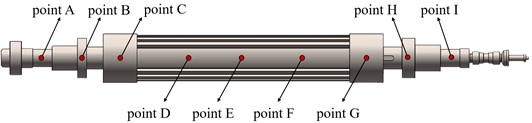
For subsequent analysis, A total of nine measurement points (A-I) are arranged along the axial direction, with their distribution shown in Fig 9. Furthermore, points A and I corresponding to bearing 1 and bearing 2 respectively; points B and H aligned with cooling fan A and cooling fan B; point E positioned at the mid-span location of the rotor shaft.
Fig. 9Measurement point location
4. Analysis of bending torsional coupling vibration characteristics
4.1. Modal and unbalanced response
Modal analysis was performed on the synchronous condenser model using the “Modal” module in ANSYS, yielding its first three bending mode shapes and corresponding critical rotational speed. Specifically, when the rotor operates near critical rotational speed, it will cause significantly increased vibration amplitudes due to resonance. The critical rotational speed primarily depends on the rotor’s intrinsic properties and the supporting stiffness. A higher rotor mass or lower support stiffness generally leads to a lower critical rotational speed. The bending mode shapes are displayed in Fig. 10. Table 4 presents the critical rotational speed and frequency of the first three modes for the investigated large synchronous condenser provided by the manufacturer. The results show that the first three critical rotational speed closely match the frequency.
Fig. 10The first three bending vibration modes of the condenser

a) First-order bending vibration mode

b) Second-order bending vibration mode

c) Third-order bending vibration mode
Table 4The first three bending modes correspond to the critical rotational speed and frequency
Vibration mode | Critical rotational speed (Hz) | Frequency (Hz) |
First-order bending vibration mode | 11.93 | 11.53 |
Second-order bending vibration mode | 31.27 | 32.00 |
Third-order bending vibration mode | 89.46 | 89.91 |
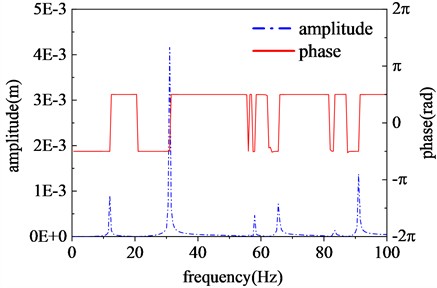
The harmonic response of the rotor under unbalanced forces was analyzed using the “Harmonic Response” module in ANSYS Workbench. During the analysis, radial unbalanced forces perpendicular to each other and with a 90° phase difference were applied to the rotor surface. The frequency range was set from 0 to 100 Hz with a solution interval of 1 Hz, and the full method was employed for the harmonic response analysis. The results are presented in Fig. 11, which clearly shows that the three highest amplitude peaks occur at approximately 12 Hz, 32 Hz, and 91 Hz. These values correspond closely to the first three flexural natural frequencies obtained from the modal analysis, thereby validating the accuracy of modal analysis.
Fig. 11Harmonic response of the rotor
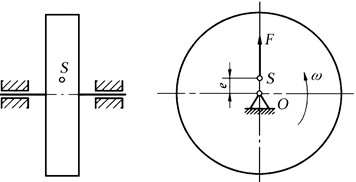
Rotor static unbalance is one of the most fundamental and prevalent types of imbalances in rotating machinery. Its core characteristic is that the mass center of the rotor does not coincide with its rotational axis. This imbalance is detectable under static conditions, as illustrated in Fig. 12. It can be achieved by adding or removing mass in a single plane to restore coincidence between the center of gravity and the rotational axis.
Fig. 12Schematic diagram of static imbalance
The simplified formula from ISO 21940 for rotor balancing is given in Eq. (18), based on which the allowable unbalance mass-radius product can be calculated:
where, is the permissible unbalance mass; is the rotational mass of the component; is the balancing quality grade; is the correction radius; is the angular velocity.
Therefore, the allowable unbalance force can be expressed as Eq. (19):
In the transient analysis, the unbalance force is applied as a time-dependent function that reflects the rotational periodicity, with force components defined as Eq. (20):
At the operational speed of 3000 rpm, apply the unbalanced force calculated by Eq.(20) to the rotor. After rotor dynamic analysis, taking point D as the monitoring point, the unbalance response spectrum is shown as Fig. 13, revealing a maximum vibration amplitude of 3.13 μm.
Fig. 13Static unbalance response
4.2. Influence of inter turn short-circuit torque on shaft bending vibration
The schematic diagram of the inter-turn short-circuit in the stator winding is shown in Fig 14. Under normal operation, the stator winding employs a three-phase wye-connected configuration with dual parallel branches per phase, where represents the neutral point. The three-phase stator windings are designated as A, B, and C, with each phase comprising two parallel branches. for instance, phase A comprises branches and , the currents in branches and are and , respectively; the current of phase A is . The other two phases follow the same pattern.
Fig. 14Schematic diagram of stator inter-turn short-circuit structure

When two or more adjacent turns within the same winding become short-circuited, it will generate electromagnetic torque on the entire system, which will affect the vibration of the rotor. When inter-turn short-circuits occur during rotor operation, the instantaneous torque varies depending on the proportion of shorted turns. The peak instantaneous torque relative to the rated torque can be approximated by Eq. (21):
where, is the proportion of shorted turns; is the proportionality coefficient (Non-salient pole machines: ≈ 0.1, Salient-pole machines: ≈ 0.15).
The rated torque is calculated as Eq. (22):
where, Prated is the rated power.
This study investigates four inter-turn short-circuit scenarios with 5 %, 15 %, 30 %, and 50 % shorted turns respectively. The peak instantaneous torques reach 3 %, 8 %, 15 %, and 20 % of the rated torque. The peak instantaneous torques calculated for different short-circuit scenarios are shown in Table 5.
Table 5Peak instantaneous torque under different short-circuit conditions
The proportion of shorted turns | / N·m |
5 % | 11729 |
15 % | 25307 |
30 % | 41111 |
50 % | 58783 |
At = 0.5 s, apply instantaneous torques corresponding to four short-circuit conditions to the synchronous compensator model under static unbalance. Take point D as the monitoring point, its amplitude variation is shown in Fig. 15.
Fig. 15The influence of short circuit turns ratio on rotor vibration under static unbalance

a) 5 % short-circuit condition

b) 15 % short-circuit condition

c) 30 % short-circuit condition

d) 50 % short-circuit condition
The results demonstrate that under the condition of 5 %, 15 %, 30 %, and 50 % short-circuit conditions, the maximum vibration amplitudes reached 3.34 μm, 4.02 μm, 5.41 μm, and 7.20 μm respectively, representing increases of 6.71 %, 28.43 %, 72.84 %, and 130.0 3% compared to before the short-circuit condition.
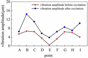
Taking the 15 % inter-turn short-circuit condition as the research subject, analyzes the maximum vibration amplitudes along the axial direction before and after the application of transient torque at various measurement points. The results are presented as Fig. 16.
As shown in Fig. 14, under static unbalance conditions, the synchronous compensator rotor exhibits its maximum vibration amplitude of 4.56 μm at point I during operational speed. After torque excitation, the maximum vibration amplitudes are observed at points B and I, reaching 9.23 μm and 9.32 μm respectively. These values represent increases of 242.4 % and 104.4 % compared to before the short-circuit condition.
Changing the imbalance type on the rotor, and analyze its vibration characteristics under dynamic unbalance. Dynamic unbalance refers to uneven rotor mass distribution, which generates both centrifugal forces and a couple moment. It must adjust the mass distribution on two separate correction planes to counteract force and torque. The schematic diagram is shown in Fig. 17.
Fig. 16Vibration amplitude variation before/after short circuit under static imbalance
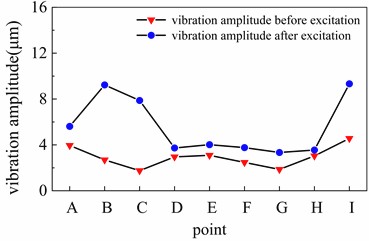
Fig. 17Schematic diagram of dynamic imbalance

The dynamic unbalance magnitude acting on the rotor can be calculated by Eq. (23):
where, is the distance between cooling fan A and cooling fan B.
In the transient analysis, the dynamic imbalance load is applied through functional loading based on rotational periodicity characteristics. The dynamic unbalance is decomposed into a sine function in the -direction and a cosine function in the -direction, both expressed as functions of time. The expression is shown in Eq. (24):
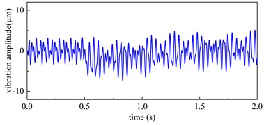
At the operational speed of 3000 rpm, apply dynamic imbalance to the rotor for analyzing. Take point D as the monitoring point, the dynamic imbalance response spectrum is shown in the Fig. 18. The result shows that the maximum vibration amplitude is 3.7 μm.
At = 0.5 s, apply instantaneous torques corresponding to four short-circuit conditions to the synchronous compensator model under dynamic unbalance. Select point D as the monitoring point, its amplitude variation is shown in Fig. 19.
The results demonstrate that under the condition of 5 %, 15 %, 30 %, and 50 % short-circuit condition, the maximum vibration amplitudes reached 4.32 μm, 5.68 μm, 7.26 μm, and 10.11 μm respectively, representing increases of 16.76 %, 53.51 %, 96.49 %, and 173.24 % compared to before the short-circuit condition.
Taking the 15 % inter-turn short-circuit condition as the research subject, analyzes the maximum vibration amplitudes along the axial direction before and after the application of transient torque at various measurement points. The results are presented as Fig. 20.
Fig. 18Dynamic unbalance response at point E
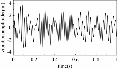
Fig. 19The influence of short circuit turns ratio on rotor vibration under dynamic unbalance

a) 5 % short-circuit condition

b) 15 % short-circuit condition
c) 30 % short-circuit condition
d) 50 % short-circuit condition
Fig. 20Vibration amplitude variation before/after short-circuit under dynamic imbalance
As evidenced in Fig. 18, under dynamic imbalance conditions, the vibration of the rotor is close to the bending vibration mode of the second sister, meaning the vibration amplitudes at the middle and both ends of the rotor are relatively lower. After torque excitation, the maximum vibration amplitudes are observed at point B, reaching 6.65 μm, increasing 116.6 % compared to before the short-circuit condition.
By comparing the vibration response of the rotor under static and dynamic unbalance, it can be found that the vibration amplitude of the rotor is larger under dynamic unbalance, and the proportion of amplitude increase is also higher under torque excitation than under static unbalance. This is because the operating speed of the rotor approaches the second-order critical rotational speed, and dynamic unbalance can also cause the rotor vibration mode to approach the second-order bending vibration mode. The combined effect of them will amplify the amplitude. Therefore, during industrial operation, it is advisable to avoid the second-order critical rotational speed and minimize unbalance, particularly dynamic unbalance.
Additionally, as shown in Fig. 14 and 17, under both static and dynamic unbalance conditions, the rotor’s vibration amplitude increases with the proportion of shorted turns after torque excitation. Reference [26] conducts research on eccentric faults, concluding that under the influence of varying degrees of inter-turn short-circuit, the changes in the rotor vibration and stator circulating current of the synchronous motor in both the time and frequency domains follow the same trend. The research results of this reference are consistent with this paper.
5. Conclusions
This article investigates the coupled bending-torsional vibration mechanism of rotors under transient torque excitation induced by inter-turn short-circuit in excitation windings. Both theoretical and finite element analytical models of the rotor were established, with the principal findings summarized as follows:
1) Established the math model of rotor bending-torsion coupling, and verified its accuracy by using the fourth-order Runge-Kutta method. And the existence of bending-torsion coupling phenomena in the rotor system has been experimentally verified.
2) A finite element analysis model of a condenser rotor was established, and the first three bending frequencies were determined to be 11.93 Hz, 31.27 Hz, and 89.46 Hz. The accuracy of the finite element model was verified by comparing it with the frequency and harmonious response.
3) Under both static and dynamic imbalance conditions, the vibration amplitude of the rotor increases with the increase of the shorted turn ratio. Consistent with the research results of existing relevant literature.
4) At the operational speed, the rotor’s mode shape under dynamic unbalance approaches the second-order bending vibration mode. Therefore, the vibration amplitude before and after being stimulated is larger than that under static imbalance. This can provide valuable guidance for industrial applications.
In this study, the bearing properties implemented feature equivalent linearized stiffness, with values remaining invariant under varying load conditions. It’s a limitation of the study, reference [27] and [28] provides relevant methodologies in this field. Besides, this study also does not consider thermal effects, which may introduce errors in the computational results. Therefore, future research should address the limitations identified in this study to enable more comprehensive investigations.
References
-
G. Xu, Y. Wang, Z. Li, and Y. Xiao, “Stator temperature rise of synchronous condenser affected by temperature variation at rotor airflow outlet,” International Journal of Electrical Power and Energy Systems, Vol. 169, p. 110772, Aug. 2025, https://doi.org/10.1016/j.ijepes.2025.110772
-
W. Ma et al., “Research on state early warning method for reactive power compensation devices,” Journal of Physics: Conference Series, Vol. 3079, No. 1, p. 012021, Aug. 2025, https://doi.org/10.1088/1742-6596/3079/1/012021
-
S. Gong, J. Yao, X. Chen, Y. Yang, and Z. Wang, “Analysis of sub-synchronous interaction and damping characteristics of weak grid-connected high inertia energy storage synchronous condenser system,” International Journal of Electrical Power and Energy Systems, Vol. 169, p. 110801, Aug. 2025, https://doi.org/10.1016/j.ijepes.2025.110801
-
K. G. H. Mangunkusumo, A. Rizqiawan, S. Sriyono, B. S. Munir, P. A. Pramana, and M. Ridwan, “Enhancing grid stability in renewable energy systems through synchronous condensers: a case study on dedieselization and assessment criteria development,” Energies, Vol. 18, No. 6, p. 1410, Mar. 2025, https://doi.org/10.3390/en18061410
-
H. Zhang, X. Heng, A. Wang, T. Liu, Q. Wang, and K. Liu, “Analysis of unbalance response and vibration reduction of an aeroengine gas generator rotor system,” Lubricants, Vol. 13, No. 6, p. 266, Jun. 2025, https://doi.org/10.3390/lubricants13060266
-
C. Wei, H. Li, X. Wang, C. Yang, W. Wang, and M. Cheng, “Discrimination method of interturn short-circuit and resistive unbalance faults for synchronous condenser,” IEEE Access, Vol. 9, pp. 129706–129717, Jan. 2021, https://doi.org/10.1109/access.2021.3112472
-
C. Xia, C. Jiang, D. Yu, Y. Liu, and C. Sun, “Diagnosis and treatment of oil film whirl fault in the bearing of large synchronous condenser,” Journal of Physics: Conference Series, Vol. 2731, No. 1, p. 012011, Mar. 2024, https://doi.org/10.1088/1742-6596/2731/1/012011
-
Y. Chen, Z. Zhao, H. Zhang, X. Li, and Z. Shi, “Analytical and experimental investigation of nonlinear dynamic characteristics of hydrodynamic bearings for oil film instability detection,” Machines, Vol. 13, No. 6, p. 444, May 2025, https://doi.org/10.3390/machines13060444
-
H. Sun, P. Fang, H. Peng, M. Zou, and Y. Xu, “Theoretical, numerical and experimental studies on double-frequency synchronization of three exciters in dynamic vibration absorption system,” Applied Mathematical Modelling, Vol. 111, pp. 384–400, Nov. 2022, https://doi.org/10.1016/j.apm.2022.06.039
-
J. Yuan, X. Dong, G. Niu, and X. Ge, “Fault detection of synchronous motor inter-turn short circuit based on current residual harmonic characteristics,” Proceedings of the Institution of Mechanical Engineers, Part C: Journal of Mechanical Engineering Science, Vol. 239, No. 15, pp. 6238–6257, Apr. 2025, https://doi.org/10.1177/09544062251333281
-
J. Li, C. Zhang, Y. He, X. Hu, J. Geng, and Y. Ma, “Impact of inter-turn short circuit in excitation windings on magnetic field and stator current of synchronous condenser under unbalanced voltage,” Energies, Vol. 16, No. 15, p. 5695, Jul. 2023, https://doi.org/10.3390/en16155695
-
A. H. Baharvand, S. Hossein Beigi Fard, A. H. Poursaeed, and M. Doostizadeh, “An optimized classifier chains‐based deep learning framework for inter-turn fault diagnosis in permanent magnet synchronous motors,” Applied Soft Computing, Vol. 180, p. 113482, Aug. 2025, https://doi.org/10.1016/j.asoc.2025.113482
-
R. Pérez, J. Cros, and M. Picard, “Real-time modeling of static, dynamic and mixed eccentricity in permanent magnet synchronous machines,” Machines, Vol. 13, No. 2, p. 120, Feb. 2025, https://doi.org/10.3390/machines13020120
-
Y. Chen, L. Zhao, L. Li, K. Liu, and C. Ye, “Digital twin-based online diagnosis method for inter-turn short circuit fault in stator windings of induction motors,” Energies, Vol. 18, No. 12, p. 3063, Jun. 2025, https://doi.org/10.3390/en18123063
-
M. Houili, M. Sahraoui, A. J. Marques Cardoso, and A. Alloui, “Zero-sequence voltage outperforms MCSA-STFT for a robust inter-turn short-circuit fault diagnosis in three-phase induction motors: a comparative study,” Machines, Vol. 13, No. 6, p. 501, Jun. 2025, https://doi.org/10.3390/machines13060501
-
C. J. Morales-Perez, D. Camarena-Martinez, J. P. Amezquita-Sanchez, J. J. Rangel-Magdaleno, E. E. S. Ramírez, and M. Valtierra-Rodriguez, “Early detection of inter-turn short circuits in induction motors using the derivative of stator current and a lightweight 1D-ResNet,” Computation, Vol. 13, No. 6, p. 140, Jun. 2025, https://doi.org/10.3390/computation13060140
-
M. S. Aziz, J. Zhang, S. Ruzimov, and X. Huang, “Detection and localization of rotor winding inter-turn short circuit fault in DFIG using zero-sequence current component under variable operating conditions,” Sensors, Vol. 25, No. 9, p. 2815, Apr. 2025, https://doi.org/10.3390/s25092815
-
A. Zorig, S. Hedayati Kia, A. Chouder, and A. Rabhi, “A comparative study for stator winding inter-turn short-circuit fault detection based on harmonic analysis of induction machine signatures,” Mathematics and Computers in Simulation, Vol. 196, pp. 273–288, Jun. 2022, https://doi.org/10.1016/j.matcom.2022.01.019
-
P. Xin, B. Ge, D. Tao, and P. Lv, “Electromagnetic torque characteristics analysis of nuclear half-speed turbine generator with stator winding inter-turn short circuit fault,” Journal of Electrical Engineering and Technology, Vol. 16, No. 4, pp. 2055–2063, Apr. 2021, https://doi.org/10.1007/s42835-021-00723-7
-
Y. Wu, Y. Li, H. Li, and W. Zhang, “An analysis of the impact of rotor winding interturn short circuits on turbine generator operating variables,” Electric Power Components and Systems, Vol. 43, No. 6, pp. 674–684, Apr. 2015, https://doi.org/10.1080/15325008.2014.999144
-
S. Wan, Y. Zhang, and Y. Hu, “Analysis of impact of rotor winding inter-turn short circuit faults on electromagnetic torque.,” (in Chinese), Electric Machines and Control, Vol. 16, No. 8, pp. 17–22, 2012, https://doi.org/10.15938/j.emc.2012.08.008
-
W. Wang et al., “Mechanism analysis of inter-turn short circuit fault for new synchronous condenser,” (in Chinese), Proceedings of the CSEE, Vol. 44, No. 3, pp. 1195–1205, 2024, https://doi.org/10.13334/j.0258-8013.pcsee.222695
-
X. Wang, R. Zhu, and X. Wang, “Analysis of bending and torsional vibration characteristics of rotor under the influence of air gap eccentricity-rub impact coupling fault,” Journal of Physics: Conference Series, Vol. 2825, No. 1, p. 012025, Aug. 2024, https://doi.org/10.1088/1742-6596/2825/1/012025
-
C. Pany, “A dynamic instability study of shallow shell panels with simply supported edges,” Journal of Polytechnic, May 2025, https://doi.org/10.2339/politeknik.1622599
-
C. Pany, “Panel flutter numerical study of thin isotropic flat plates and curved plates with various edge boundary conditions,” Journal of Polytechnic, Vol. 26, No. 4, pp. 1467–1473, Dec. 2023, https://doi.org/10.2339/politeknik.1139958
-
M. Ma, Y. Hou, Y. Li, P. He, M. Jiang, and Y. Wu, “Analysis of rotor winding interturn short circuits affected by the initial dynamic eccentricity in large synchronous condensers,” IET Electric Power Applications, Vol. 16, No. 6, pp. 736–748, Apr. 2022, https://doi.org/10.1049/elp2.12191
-
C. Pany, “Large amplitude free vibrations analysis of prismatic and non-prismatic different tapered cantilever beams,” Pamukkale University Journal of Engineering Sciences, Vol. 29, No. 4, pp. 370–376, Jan. 2023, https://doi.org/10.5505/pajes.2022.02489
-
C. Pany and G. V. Rao, “Large amplitude free vibrations of a uniform spring-hinged beam,” Journal of Sound and Vibration, Vol. 271, No. 3-5, pp. 1163–1169, Apr. 2004, https://doi.org/10.1016/s0022-460x(03)00572-8
About this article

This research was supported by State Grid Corporation of China Technology Project (5500-202416156A-1-1-ZN).
The datasets generated during and/or analyzed during the current study are available from the corresponding author on reasonable request.
Lyu Xuebin: conceptualization, investigation. Ren Jie: formal analysis, funding acquisition. Li Ming: project administration, resources. Huang Jinjun: software, supervision. Quan Jingzhou: writing-original draft. Zhang Wanfu: writing-review and editing, validation. LI Chun: methodology.
The authors declare that they have no conflict of interest.
