Abstract
To account for the phenomenon that the winding inter-turn short circuit fault of the turbine generator rotor leads to intensified vibration, a coupled nonlinear vibration model of the oil film force and electromagnetic force is established, and a dynamic stability analysis method is proposed. An improved shooting method for solving the periodic solutions of the bearing-rotor system with the unbalanced electromagnetic force is developed; and the system damping criterion used in examining the system stability margin is presented. The calculation on the nonlinear vibration for the 300 MW turbine generator is finished, and the vibration response characteristics and instability margin in a typical winding inter-turn short circuit fault are obtained. The results show that the winding inter-turn short circuit fault may result in the synchronized vortex phenomenon, and a comparison between the numerical results and the site test results is completed. The results will provide technical support and theoretical basis for directly predicting the winding inter-turn short-circuit fault via the vibration detection.
1. Introduction
The winding inter-turn short circuit fault is found to occur frequently in the turbine generator rotor, and when it occurs, the equilibrium state of the magnetic field of the motor air gap is disturbed, which leads to intensified vibration and thereby seriously undermines the safety of the rotor [1, 2]. The rotor vibration in case of the winding inter-turn short circuit is a nonlinear vibration, which couples the electromagnetic force attributable to a short circuit and the nonlinear oil film force [3-5]. The existing literature is mostly concerned about site test results and laboratory simulations, but there is a clear need to investigate the vibration mechanism under the coupled forces, which may prompt the development of a new inter-turn short circuit fault identification (or recognition) technology through rotor vibration monitoring. For the rotor-bearing system of the turbine generator, the electromagnetic force generated by the inter-turn short circuit fault is the unbalanced excitation force. A number of studies have been conducted on the nonlinear vibration of the rotor-bearing system caused by the unbalanced excitation force [6-10]. Lundström and Aidanpää analyzed the whirling frequencies and amplitude of the response for large synchronous generators with a high number of poles, due to deviations of shape in the rotor and stator [6]. De Castroa HF et al. [7], Wang [8] developed the expression forms of the oil film pressure distribution of the cylindrical sliding bearing for analyzing the nonlinear dynamics respectively. Wu et al. studied the circular whirling and stability of a model rotor in a synchronous generator under no load, subjected to unbalanced magnetic pull and mass eccentric force [9]. Giovanni A et al studied the dynamics of an unbalanced rigid rotor on two-lobe journal bearings with wave profile, symmetrically placed at its ends [10]. In addition, much research has been done on the analysis method of nonlinear vibration and stability [11-16]. In these researches, special models and methods are developed according to the respective complex conditions or structural characteristics of the bearing rotor system; and no work has investigated the coupled nonlinear vibration from the nonlinear oil film force and the electromagnetic force generated by the winding inter-turn short circuit fault. The present study is designed for this purpose. In distinction from other studies, the nonlinear oil film force will be directly obtained by solving the Reynolds equation with the finite element method. To improve the calculation convergence speed of the nonlinear vibration response solution, an improved shooting method is developed; and the system damping indicator is presented for assessing the system stability.
2. The nonlinear vibration model with the coupling of the oil film force and electromagnetic force
2.1. Nonlinear motion equations
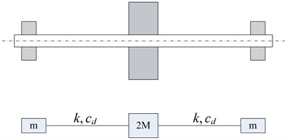
The rotor is supported by two same cylindrical sliding bearings. The nonlinear oil film force of the bearing is directly obtained by solving the Reynolds equation, and the effect of the temperature-viscosity relation is considered. The motion equation, applied to the rotor-bearing system, is built to take into account the effect of viscosity and elasticity of the rotor. The model of the symmetric viscoelastic rotor bearing system is shown in Figure 1, and a linear viscoelastic model and the lumped mass method are adopted to solve the motion equation of the system.
Fig. 1Symmetric viscoelasticity rotor-bearing system model
The position coordinates of the rotor and the rigid center of the disc are defined as and , and the system satisfies the following motion equation:
where, and are the oil film force components in the horizontal and vertical directions. is the gravitational acceleration. is the rotor angular speed. is the eccentricity distance of the eccentric mass located on the rigid disc. is the phase angle. and represent the elasticity and damping coefficients of the rotor respectively, and , ( is the center distance of a pair of bearings; and are the material constants; and I is the equatorial inertia moment of the rotor cross section). and correspond to the concentrated mass of the rotor center and the disc center respectively, and , ( and represent the total mass of the rotor and the disc respectively).
Applying the following dimensionless quantities to Eq. (1), we can get the dimensionless motion equation of the rotor system as shown in Eq. (2). The dimensionless quantities include: vibration component , ; oil film force components , ; mass , ; the unbalance eccentricity ; time ; and the shaft stiffness and the damping coefficient of the rotor and (, , , and represent bearing length, diameter, radius gap, the gap ratio, and lubricating oil viscosity respectively):
As is obvious in Eq. (2), for the balancing rotor, in case of no external excitation (i.e. ), when the rotor system is in the static equilibrium position, the resultant oil film forces in the direction and the direction correspond to zero, and the total mass of the rotor and the disc respectively. The static equilibrium position, unaffected by the disk location, is contingent only on the total mass of the rotor. On the other hand, for the unbalancing rotor with external excitation (i.e. ) such as the electromagnetic force generated by the inter-turn short circuit fault in the current study, the unbalance eccentricity can obtain. The electromagnetic force is expressed as:
where is the node number of the modeling rotor. are the components of the elecromagnetic force acting on the node, and its situation and coordinate direction are consistent with that of the node of the rotor.
2.2. The nonlinear oil film force model
For the sliding bearing supporting the rotor, the nonlinear oil film pressure distribution can be obtained by solving the dynamic Reynolds equation. Whereas the relevant bearing parameters: influence the oil film pressure distribution, they are closely related to the rotor motion parameters , as:
The dynamic Reynolds equation for obtaining the bearing dimensionless oil film pressure is expressed as follows [17]:
where, is the dimensionless film thickness; is the dimensionless film pressure; is the axial dimensionless coordinates (the coordinate center is the center of the bearing, and the dimensionless unit is ); is the bearing eccentricity; is the bearing attitude angle. is the relative viscosity of the lubricating oil (22# turbine oil), and its relationship with the temperature of the lubricating oil is expressed in the following [18]:
The temperature distribution is consistent with the following energy equation [17]:
where, the relative temperature , and is oil density; is oil specific heat.
The finite element method is used to calculate the bearing oil film pressure distribution. The dimensionless finite element equation of the oil film pressure under small perturbation, derived from Galerkin Method based on Eq. (5), is expressed as:
where, is the oil film distribution area, is the shape function of the quadrilateral eight-node isoparametric element.
Substituting (4) into Eq. (8) and combining with Eq. (6) and (7), the dimensionless oil film pressure can be obtained.
The dimensionless oil film force components are derived as:
2.3. Calculation method for the periodic solution of the unbalanced rotor under the electromagnetic force
The vibration of the rotor system supported by sliding bearings under the unbalanced force is described as:
where consists of the displacement vectors and velocity vectors of the nodes of the modeling rotor. The unbalanced electromagnetic force generated by the inter-turn short circuit fault and the oil film force are included in. The coordinate center of displacement vectors is defined at the static equilibrium point of the rotor. Supposing that the period of the unbalance force is , calculation of the periodic solution of the rotor system described above in Eq. (10) is equivalent to that of the solution of the following fixed boundary value problem with period :
Eq. (10) can be reduced to one dimension using Poincare’s section because of its autonomous characteristics, and the Poincare’s section can be defined by setting the velocity component at 0. In this paper, the section where the horizontal displacement is equal to the vertical displacement and both are less than zero, is defined as the Poincare’s section, namely, .
To help obtain the in Eq. (11), we introduce the parameters vector . Once the value of reaches certain level of precision, the periodic solutions of Eq. (11) can be obtained by directly applying the routines of numerical integration to solve the algebraic equations, as show in Eq. (12):
where, is obtained by the following equation, as:
In this paper, a 4-stage Runge-Kutta method of order 4 is used to obtain the , and the integral step length is 1/50 of the period of the unbalanced exciting force. The convergence accuracy is 5 %.
The transformation from the Eq. (11) to Eq. (12) is beneficial to improving computation precision and speed, and a variety of methods to solve Eq. (12) are known as the shooting method [19]. In this paper, a quasi-Newton method for solving algebraic equations (12) is proposed, which has a wider range of convergence than otherwise. With the quasi-Newton method, the algebraic equations (12) can be solved even if the initial value is not a well-chosen one. In distinction from the general quasi-Newton shooting method, the method proposed in this paper is termed the improved quasi-Newton shooting method. We can rewrite the algebraic Eq. (12) with this shooting method with a variable parameter , into the following iteration form:
where is the number of the iteration step; is a variable parameter in for the th step; and is the difference matrix of .
In , each component can be read as:
With the components , the first row (column) of is equal to the second row (column), and . will be solved by calculating the initial value problem (Eq. (13)) n times after  is obtained. The variable parameter range is of . In this paper, with , is solved with Eq. (14). If (“” is the norm), then will be halved and the solution will be recalculated, until .
The improved quasi-Newton shooting method in this paper has a wide range of convergence, and the number of iterations is less than that of the Newton shooting method. Nonetheless, it has to calculate the new difference quotient matrix for each iteration so that when is quite large, the time cost will be very high. As a result, in this paper, we also present a new quasi-Newton method for solving the algebraic equation (12), which does not calculate the difference quotient matrix, with the Broyden rank being 1. With this method, although the time cost in each iteration is higher than that of the Newton method, it has obvious advantages, especially in case of a large . This new quasi-Newton method with Broyden rank being 1 takes a similar form to Eq. (14), as in:
where is the parameter introduced in this paper, with the same purpose and usage as that in Eq. (14). Vector is computed by subtracting the first element from, and similarly vector is computed by subtracting the first element from . Furthermore, iterative Eq. (14) can be rewritten as the iterative formula concerning , which will facilitate the discussion on the stability of the system in the next section. is n-dimensional matrix introduced in reference [20]. When , is a unit matrix; when , it can be solved via the following formula:
To distinguish it from the general Broyden shooting method, the method introduced in this paper is called the improved Broyden shooting method. In brief, the convergence time cost of the two improved shooting methods is better than that of the general shooting method. In terms of the time cost, the improved quasi-Newton shooting method is preferred in the lower dimension system whereas the improved Broyden shooting method is favored in the higher dimension system.
When Eq. (12) is solved using the iterative Eq. (14) or (15), the convergence criteria is as follows:
where is a given accuracy. After and , which meet the requirement of the aforementioned formula, are obtained, the periodic solution (the period is ) will be calculated through Eq. (13).
2.4. Analysis method for the stability motion state of the rotor system
The Floquet theory is adopted to study the stability of the imbalance incentive periodic solution . For this purpose, it is necessary to solve the standard-based solution matrix of , with time being ; where is the disturbance vector , and is the period of the unbalanced exciting force,.
Solving of , , is the initial value problem, and (unit matrix) under the condition. However, to obtain , it is not necessary to directly solve the above equation. Instead, can be obtained by developing the relationship between and the difference quotient matrix of the aforementioned shooting method. The partial derivative of Eq. (13) is written as :
Then . From Eq. (12) we get . When replacing with the difference quotient matrix , we then obtain . Once a periodic solution that is precise enough is obtained, the difference quotient matrix can be recalculated. In doing so, can be obtained.
With the Floquet theory, the characteristic matrix , the eigenvalues (characteristic coefficient) of the matrix can be determined by the following formula, as:
reflects the convergence characteristics of periodic solutions under the unbalanced incentive condition. The real part is uniquely determined by formula (19), but the imaginary part is not uniquely determined. Assuming , where ; and , the periodic solution stability margin indicator, namely, the characteristics damping, is presented, as:
Based on the Floquet theory, the stability criteria of the unbalanced incentive periodic solution, namely, is described as follows: When is greater than zero, then it is in the stable state; when is less than zero, then it is in the unstable state; and when is equal to zero, it is in the critical state.
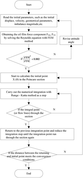
The whole calculation flow chart of the nonlinear dynamics coupling the nonlinear oil film force and the electromagnetic force induced by the inter-turn short circle fault is show in Fig. 2.
Fig. 2Nonlinear dynamics flowchart
The quantitative motion state of the instable rotor system and its convergence are determined by the time Poincaré mapping method. The procedures are as follows:
1) Define , , , , where, ' represents ; is the initial bearing journal center position, as show in Eq. (2), also, the static equilibrium position.
2) Make , and take as the starting point. We can obtain by solving Eq. (2). According to the Poincaré definition [19], the mapping point , and the orderly mapping point column are obtained, and is taken as the flag value.
3) Check the convergence precision of the possible branch flag value and determine if it has met the convergence requirement, as:
where is the period of the excitation force; is the convergence precision (5 % in this paper). When the mapping point is basically “fixed”, we can determine that the rotor system arrives at the steady motion state [20].
3. Stability and nonlinear vibration analysis of a 300 MW generator rotor with the inter-turn short circuit fault
3.1. Calculation object and processes
A Dongfang 300 MW generator bearing-rotor system is taken as the research object. The main geometrical parameters and working parameters of the two same supporting bearings are shown in Table 1. The main parameters of the rotor are listed in Table 2. The model of the modeling rotor is consisted of 9 nodes and 8 segments, as shown in Figure 3. The generator rotor model and its fault positions (0° position, 90° position and 180° position) are described in Figure 4. In this paper, we will simulate the nonlinear vibration with the serious 90° position inter-turn short circuit fault (the affected turns are about 25 % of the total turns) when the rotor is at the rated speed of 3000 rpm. The electromagnetic force and the corresponding imbalance magnitude generated by the inter-turn short circuit fault are given in Table 3.
Fig. 3Dynamic model for the generator rotor
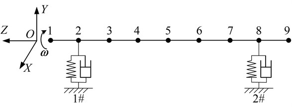
Table 1Bearing and working conditions parameters
Parameter | Value | Parameter | Value |
Length / mm | 380 | Load / kg | 26405 |
Diameter / mm | 450 | Ellipticity | 0.566 |
Oil viscosity (Pa·S) | 0.0126 | Oil type | 32# |
Oil inlet pressure / MPa | 0.08 | Radius clearance / mm | 0.675 |
Table 2Main parameters of the generator rotor
Parameter | Value |
Span between both the two bearings / mm | 8000 |
Mass / kg | 52810 |
Speed / rpm | 3000 |
Moments of inertia / kg·m2 | 7365 |
Table 3Electromagnetic force and imbalance magnitude
Condition | Imbalance magnitude | |||
Normal | 0 | 0 | 0 | 0 |
90° position serious fault | 13702 | 127110 | 0.00078 | 0.00723 |
Fig. 4Generator model and diagram for the short circuit location
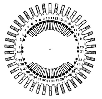
a) Turbine generator model
b) Diagram for the inter-turn short circuit location
4. Results and discussion
4.1. Calculation process and convergence analysis
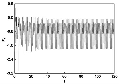
The characteristics damping of the balance rotor in its normal state (at the rated speed of 3000 rpm) is 0.0695; and the critical unbalanced excitation force of the rotor at its rated speed is approximately 8747.50 N (). The range of the unbalanced electromagnetic force generated by the inter-turn short circuit fault is between 12213 and 127110 N. Therefore, it can be concluded that the rotor will fall into the unstable state when the fault occurs. Given that the motion state of the rotor in case of instability varies with the electromagnetic force value, we will investigate the nonlinear vibration in one specific fault mode (90° position short circuit serious fault). Figure 5 shows the convergence process. The flag changes with the solution period. As shown in Fig. 5, when the 120 T period is reached, the convergence precision given in Eq. (21) 4.37 % < 5 %, and thus the calculation is completed.
4.2. Discussion
The coordinates of the horizontal and vertical displacements and oil film force are shown in Figure 6. In Fig. 6, is the bearing loads; , , and are dimensionless parameters; the relative units of are the side clearance of bearings , the relative unit of is . The results obtained in this paper include the displacement periodic solutions of nodes (2, 3, 4, 5 shown in Fig. 3) which are read as , , , , , , , , and the waveform of the oil film force . The horizontal ordinate in the following figures represents the dimensionless time period in radians, and when the unit is second, . The maximum value of the horizontal ordinate is the cycle number of the stable periodic solutions. The vertical ordinate of the nonlinear vibration response and the rotor centerline orbit are the relative vibration amplitude between the actual vibration response amplitude and the bearing side of the gap . The vertical ordinate for the transient oil film force waveform is the ratio of the oil film force to the bearing loads.
Fig. 5Motion convergence process
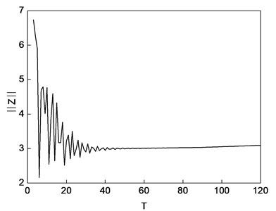
Fig. 6Coordinate system (O is the center of bearing)
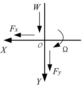
Figure 7 shows the rotor centerline orbit and the nonlinear vibration response generated by the electromagnetic force under the 90° position serious short circuit fault condition. Figure 8 is the waveform diagram of the transient process of the oil film force.
The FFT for the vibration response in the steady motion state is completed under the 90° position serious fault condition, and the maximum, minimum displacements and amplitude of the steady-state solution (for nodes 2, 3, 4, 5 and oil film force) are listed in Table 4. The harmonic components of the vibration response in nodes 2, 3, 4, 5 and the oil film force are shown in Table 5.
Table 4Maximum, minimum displacements and amplitude in case of 90° position serious fault
Node | ||||||
Max. | Min. | P-P | Max. | Min. | P-P | |
2 | 0.5977 | –0.2356 | 0.4166 | 0.2230 | –0.1693 | 0.1962 |
3 | 0.5444 | –0.1022 | 0.3233 | 0.3346 | –0.2679 | 0.3012 |
4 | 0.4985 | –0.0022 | 0.2504 | 0.3444 | –0.2969 | 0.3207 |
5 | 0.4438 | 0.0475 | 0.1981 | 0.3209 | –0.2956 | 0.3083 |
Oli film force | 0.6299 | –0.4903 | 0.5601 | –0.0621 | –1.7989 | 0.8684 |
Table 5Harmonic components in case of 90° position serious fault
Node | ||||||
Vortex speed | ||||||
2 | 0.3760 | 0.0642 | 0.0002 | 0.1684 | 0.0329 | 0.0001 |
3 | 0.2958 | 0.0269 | 0.0001 | 0.2735 | 0.0128 | 0.0001 |
4 | 0.2323 | 0.0048 | 0.0000 | 0.2921 | 0.0030 | 0.0000 |
5 | 0.1687 | 0.0298 | 0.0001 | 0.2824 | 0.0170 | 0.0001 |
Oli film force | 0.3458 | 0.1460 | 0.0005 | 0.5462 | 0.2627 | 0.0009 |
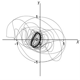
Fig. 7Rotor centerline orbit under 90° position serious fault
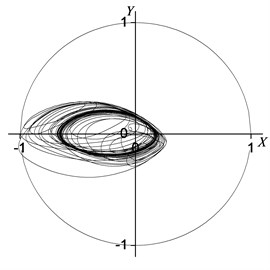
a) Node 2
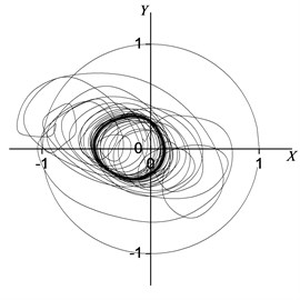
b) Node 3
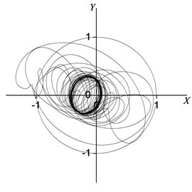
c) Node 4
d) Node 5
Fig. 8Oil film force under 90° position serious fault
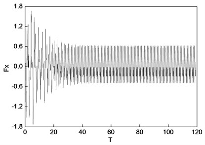
a) Horizontal direction
b) Vertical direction
As is obvious in Figures 7 and 8, the steady motion state of the rotor system is a synchronized vortex. Figure 7 shows the rotor centerline orbit of the periodic motion. The results in Tables 4 and 5 show that the system motion is the constant periodic motion (the period is ), and the main motion state is a synchronized vortex. The vibration responses in Node 2 (the center of the bearing) with the synchronizing component in the horizontal and vertical directions are 0.376 and 0.168 respectively; and the horizontal and vertical vibration sync components in the Node 5 (rotor symmetrical center) are 0.169 and 0.282, respectively. The synchronizing components of the oil film forces in the horizontal and vertical directions are 0.346 and 0.546 respectively. Meanwhile, as can be seen from Tables 4 and 5, due to the electromagnetic force induced by the inter-turn short-circuit fault, the vibration amplitudes of the rotor system in Node 2, 3, 4 and 5 are excited. Compared with the normal case, the vibration amplitudes in the horizontal and vertical directions of Node 2, 3, 4 and 5 increase to 425 %, 168 %, 80 %, 28 % and 2702 %, 186 %, 164 %, 129 % respectively. The horizontal and vertical oil film forces effected by the electromagnetic force increase to 367 % and 728 %, respectively.
4.3. A comparison with the site test results
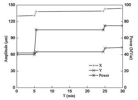
The above research object is from a power plant in Huangshi City, Hubei Province, China. The tested 300 MW generator unit is labeled as No. 2, which is used with the cooling fluid of water - hydrogen. The bearings supporting the generator rotor are labeled as the #7, #8 bearing respectively. Nodes 2 and 8 Figure 3 indicates the position, where the bearings are assembled. #7 and #8 bearings are at nodes 2 and 8 respectively. In 2005, an emergency stop occurred on the generator units, and the loss excitation protection action aroused. The duration of the asynchronous loss excitation conditions was about 14 s, and the current in the rotor was up to 16 kA. After re-booting, we found that the vibration in #7, #8 bearings was abnormal and the (running frequency) component vibration was intensified. Therefore, we conducted a reactive power test. During the test, the active power was maintained at 107 MW, and the reactive power increased from 42 MVar, to 70 MVar, and finally to 75 MVar. The increase of the reactive power reflected that of the rotor current. The relation between vibration amplitude in the bearing (#7 bearing) and the reactive power is shown in Figure 9. From Fig. 9, we can see that the vibration in the horizontal and vertical directions increased with the reactive power.
Fig. 9Rotor vibration amplitude vs. reactive power
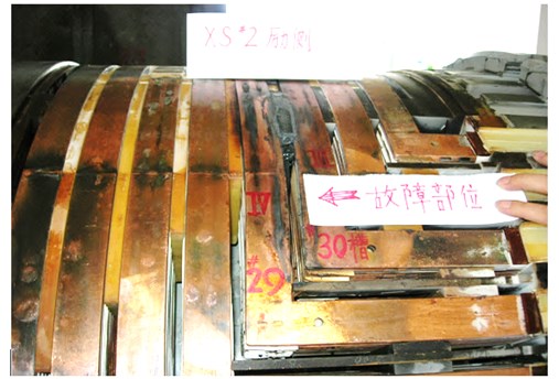
After the shutdown of the generator unit, the detected insulation of the excitation winding to ground was . AC impedance value of the excitation winding was reduced to about 40 % of the normal unit. Voltage was applied to two slip rings of the rotor, and voltage values measured at two slip rings to the ground were significantly different. The implication was that the sudden failure of the generator unit was due to the inter-turn short circuit fault. For further examination, the generator unit was dismantled, and we found that the ground insulation was breakdown at approximately 90° (shown in Figure 4) position of the rotor symmetrical center. The fault led to the direct inter-turns short circuit from the upper incoming coil turn #30 slots to the upper outlet coil turn #29 slots, and the total number of the short circuit coil turns was up to 25 % of that of the whole field winding turns. Undoubtedly, it was a very serious inter-turn short circuit fault. The photo on the fault position of the dismantled generator rotor is shown in Figure 10.
Fig. 10Photo of field winding inter-turn fault in generator rotor
The results in section 4.2 show that vibration amplitude (Node 2, the bearing situation) in the horizontal direction (X direction) is 142 μm (0.4166×0.675/2 = 142 μm), and the vertical direction (Y direction) is 66 μm (0.1962×0.675/2 = 66 μm) (as shown in Table 4). The test results in Figure 9 show that the measured vibration amplitudes in the horizontal and vertical directions were about 138 μ m and 71 μm respectively. Because the error between theoretical prediction and test results is lower than 10 %, the current study is of high engineering value.
5. Conclusion
1) The coupled nonlinear vibration model based on the oil film force and the electromagnetic force is established, and a dynamic stability analysis method is developed, which lends the theoretical basis to a reasonable explanation for the phenomenon that the inter-turn short circuit fault of the generator unit leads to the rotor’ increased vibration.
2) An improved quasi-Newton shooting method and an improved Broyden shooting method are presented for solving the periodic solution of the coupled nonlinear vibration model, and a new system damping indicator is also proposed for studying the unbalanced incentive periodic solution stability.
3) The vibration characteristics for a 300 MW generator unit with the 90° inter-turns short circuit serious fault based on the coupled nonlinear vibration model are discussed. The results show that the fault might lead to the synchronized vortex phenomenon. Compared with the actual test results, the error of the calculation results is lower than 10 %.
References
-
Zhang Z. P., Liu S., Yao S. J., et al. Fault Analysis and Diagnosis for the Large Generator Rotor. Beijing: China Electric Power Press, 2011, (in Chinese).
-
Wolbank T. M., Macheiner P. E. Detection of air gap eccentricity in the presence of stator inter-turn fault of inverter fed induction machines. PESC '08 - 39th IEEE Annual Power Electronics Specialists Conference, 2008, p. 2633-2638.
-
Hao L. L., Sun Y. G., Qiu A. R.,et al. Steady-state calculation and online monitoring of interturn short circuit of field windings in synchronous machines. IEEE Transactions on Energy Conversion, Vol. 27, Issue 1, 2012, p. 128-138.
-
Bachschmid N., Pennacchi P., Chatterton S., et al. On model updating of turbo-generator set. Journal of Vibroengineering, Vol. 11, Issue 3, 2009, p. 379-391.
-
Pennacchi P. Computational model for calculating the dynamical behaviour of generators caused by unbalanced magnetic pull and experimental validation. Journal of Sound and Vibration, Vol. 312, Issue 1-2, 2008, p. 332-353.
-
Lundström N. L. P., Aidanpää J. O. Whirling frequencies and amplitudes due to deviations of generator shape. International Journal of Non-linear Mechanics, Vol. 43, Issue 9, 2008, p. 933-940.
-
De Castroa H. F., Cavalcaa K. L., Nordmann R. Whirl and whip instabilities in rotor-bearing system considering a nonlinear force model. Journal of Sound and Vibration, Vol. 317, Issue 1, 2008, p. 273-293.
-
Wang Y. L., Liu Z. S. Approximate analytical model of oil-film force for cylindrical journal bearing. Proceedings of the CSEE, Vol. 31, Issue 29, 2011, p. 110-117, (in Chinese).
-
Wu B. S., Sun W. P., Zheng G. L., et al. Circular whirling and stability due to unbalanced magnetic pull and eccentric force. Journal of Sound and Vibration, Vol. 330, Issue 21, 2011, p. 4949-4954.
-
Giovanni A., Erasmo M., Salvatore S. Nonlinear behavior analysis of a rotor on two-lobe wave journal bearings. Tribology International, Vol. 44, Issue 1, 2011, p. 42-54.
-
Kim Y. B., Noah S. T. Bifurcation analysis for a modified Jeffcott rotor with bearing clearance. Nonlinear Dynamics, Vol. 1, Issue 3, 1990, p. 221-241.
-
Ghadimi M., Kaliji H. D., Barari A. Analytical solutions to nonlinear mechanical oscillation problems. Journal of Vibroengineering, Vol. 13, Issue 2, 2011, p. 133-143.
-
Zarko D., Ban D., Vazdar I., et al. Calculation of unbalanced magnetic pull in a salient-pole synchronous generator using finite-element method and measured shaft orbit. IEEE Transactions on Industrial Electronics, Vol. 59, Issue 6, 2012, p. 2536-2549.
-
Matthew B. W., Amir Y., Paul A., et al. Model reduction methods for rotor dynamic analysis: a survey and review. International Journal of Rotating Machinery, Vol. 2010, Article ID 273716, 17 pages, DOI: 10.1155/2010/273716.
-
Sedighi H. M., Reza A., Zare J. Dynamic analysis of preload nonlinearity in nonlinear beam vibration. Journal of Vibroengineering, Vol. 13, Issue 4, 2011, p. 778-787.
-
Zheng T., Hasebe N. Nonlinear dynamic behaviors of a complex rotor-bearing system. ASME Journal of Applied Mechanics, Vol. 67, Issue 3, 2000, p. 485-495.
-
Zhang G. Y. Research on the Low Viscosity Lubricating Performance and Rotor System Stability of High-Speed Turbopumps. Xi’an: Xi’an Jiaotong University, 2010, (in Chinese).
-
Zhang Z. M., Zhang Y. Y., Xie Y. B., et al. The Hydrodynamic Lubrication Theory for the Sliding Bearing. Beijing: Higher Education Press, 1986, (in Chinese).
-
Chen Y. S., Xu J. X. Nonlinear Dynamics, Nonlinear Vibration and Motion Stability. Beijing: China Science and Technology Press, 1995, (in Chinese).
-
Li Q. Y., Mo Z. Z., Qi L. Q. Numerical Algorithm of Nonlinear Equations. Beijing: Science Press, 1987, (in Chinese).
About this article

This work was supported by National Natural Science Foundation of China (Project No. 51205314) and the Project of Hubei Electric Testing & Research Institute (No. 2010-125).
