Abstract
In response to the limitations of traditional transport aircraft cargo hold barrier net test methods in terms of boundary support and load simulation, an innovative test technology framework was proposed. By establishing the full net surface cargo simulation technology supported by rigid boundary, the support constraints distributed at multiple points in actual working conditions are effectively reproduced. Furthermore, based on multi-sensor synchronous monitoring, a precise testing method for flexible structures was developed. This method tracks real-time interface load data at connection points, quantitatively analyzes the load distribution along load transfer paths, and systematically evaluates the mechanical response characteristics of the restraint net. The results demonstrate that this approach ensures the reliability of test data while significantly improving the stability of strength verification for flexible structures, successfully addressing the issues of uneven loading and result fluctuations caused by structural flexibility in traditional tests. The proposed test technology framework provides a reusable solution for strength verification of similar flexible structures, offering valuable engineering references for the safe design of air cargo system.
1. Introduction
The cargo compartment restraint net (hereinafter referred to as the restraint net) is a critical safety device in aircraft cargo systems designed to prevent excessive cargo movement during emergency landings, thereby safeguarding crew and equipment safety. Due to its prominent flexibility characteristics, low safety margins, and high experimental verification challenges, it has become a key technical challenge in the design of air cargo systems. The restraint net consists of flexible fabric straps and metal joints, with the straps sewn together to form an integrated structure and stitched to metallic connectors. These connectors interface with the aircraft’s structural framework. During emergency braking, cargo interacts with the restraint net, transferring loads through the connectors to the aircraft’s structural components.
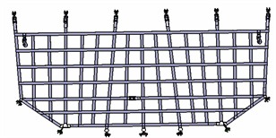
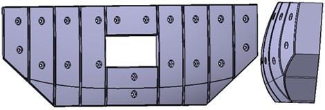
The aircraft restraint net (Fig. 1), China’s first domestically developed design, features a lattice structure composed of longitudinal load-bearing bands and transverse load-bearing bands that cross each other perpendicularly, with the longitudinal bands serving as the primary load-carrying elements.
As a special large flexible structure on aircraft, the arresting net had never been expected to achieve weight reduction prior to this. Full-scale strength testing for such flexible arresting nets had never been conducted. However, with the evolution of aircraft design philosophies, new dual requirements have emerged for arresting net design: it must not only meet its own strength specifications but also avoid excessive rigidity. In extreme scenarios, the arresting net must fail before the aircraft's airframe structure to protect the latter. Consequently, conducting full-scale strength testing for the arresting net has become imperative. As a pioneering and entirely new type of strength test, the experiment faced challenges such as boundary support distortion, inaccurate load simulation, and undefined testing procedures. The project team systematically addressed these issues through finite element analysis, installation of triaxial force sensors, and iterative pre-testing.
Fig. 1Lattice-type cargo compartment restraint net
2. Experimental challenges and research approach
Unlike conventional metallic structures, the primary load-bearing components of the restraint net are flexible fabric straps, which undergo large deformations and exhibit significant nonlinear characteristics under loading. While researchers could conduct strength tests on individual load-transfer straps, the undefined load-transfer pathways within the interwoven strap network made it impossible to verify systemic strength under operational cargo pressures, with the following key challenges.
a) The restraint net is a flexible structure with a statically indeterminate configuration, featuring 34 connection points between the net assembly and the fuselage structure. The load distribution is highly uncertain, leading to potential mismatches between experimental loading conditions and real-world loading scenarios.
b) Due to its flexibility, the restraint net cannot be directly loaded using conventional equipment. Instead, cargo dummies act as intermediate media. The contact surface shape between the dummy and the net critically influences coordinated deformation among the straps.
c) The restraint net must satisfy two conflicting design requirements: meeting its own strength requirements while avoiding excessive stiffness. In extreme conditions, the net must fail before the airframe structure to protect the airframe. Thus, the interface load at connection points with the fuselage must not exceed 10.8 kN.
Building on a qualitative analysis of the force transmission mechanisms in the flexible structure, the core challenge identified is: quantitatively analyzing the loads on each strap under loading conditions and adjusting the net’s loading state to maximize coordinated deformation among straps. Given that the primary influencing factor is the shape of the loading surface, this study proposes a structure strength optimization method based on nonlinear finite element modeling [1-4]. By applying realistic operational loads in finite element models [5-7], we obtained authentic net deformation patterns. These deformation characteristics were subsequently translated into the contoured loading surfaces of experimental fixtures, ensuring load application accuracy that mirrors actual service conditions. These insights informed the design of loading fixtures based on experimentally derived deformation shapes for physical testing. To address deformation incompatibility among load-transfer straps during testing, triaxial force sensors were installed at all constraint points. This system enabled real-time monitoring of tri-directional constraint forces, allowing empirical verification of strap load distribution compliance through inverse force deduction methodologies.
3. Simulation analysis
3.1. Modeling scheme
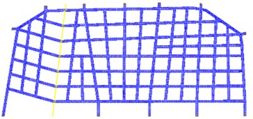
Shell elements were used to model the structural of the barrier nets, with a basic element size of 10 mm, ensuring that the proportion of triangular elements in the overall model is less than 5 %, and the element warping is less than 10. For key areas involving contact, local mesh refinement was performed, with a basic size of 5 mm. The finite element model is shown in Fig. 2, with the load constraint points consistent with the positions of the hooks applied to the barrier net. The model includes 12,628 nodes and 9,811 elements. The 2D element coordinate system is consistent with the overall coordinate system.
Fig. 2Finite element model
The restraint net is constructed from a hyperelastic material with properties listed in Table 1, including a Young’s modulus of 1.20 MPa. The flexible material skin exhibits a fracture strain of 180.5 % and a tensile strength of 2.06 MPa. The Ogden model was employed to characterize the hyperelastic nonlinear behavior of the net, simulating its deformation performance. Engineering empirical parameters were incorporated to enhance the nonlinear analysis. The strain energy function of the Ogden model is expressed as:
where: , , are the principal stretch ratios (deformed length divided by original length) (; and are material parameters determined through fitting with existing experimental data; is the number of model terms, with higher improving the model’s fidelity to complex deformations. For this study, 3.
Table 1Initial parameters for Ogden constitutive model
2 | 0.707 | 0.707 | 1.5 | 5.0 | 5.0 |
3.2. Analysis results
The simulated structural deformation of the restraint net aligns closely with physical test results, with displacement errors below 1 % (Fig. 3).
4. Physical experiments
4.1. Loading surface simulation
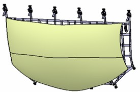
The deformation of the restraint net is influenced by cargo shape, flexibility, and contact area. In practical applications, the complexity and variability of cargo shapes and deformation behaviors make it impractical to quantitatively analyze their effects on net deformation. Additionally, precisely controlling cargo shape and deformation during testing to match the net’s deformation is technically challenging. Therefore, the experiment focused solely on the contact surface shape of the cargo dummy, designing a loading surface that aligns with the net’s deformation characteristics. Based on the results from virtual experiments (Fig. 4), the loading surface was designed to cover the entire net area.
The projected area of the loading surface perpendicular to the load direction is 2700 mm ×1250 mm, which is too large for fabrication using steel due to excessive weight. Hardwood was chosen as the material because it does not deform under the net’s load and satisfies strength and stiffness requirements. The surface must be sanded smooth to prevent damage to the net straps.
Fig. 3Displacement results
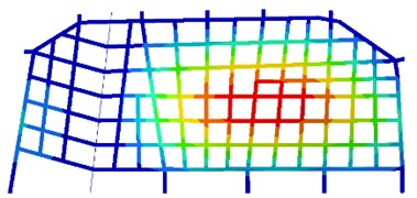
Fig. 4Full-network loading surface
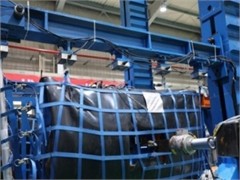
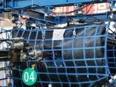
Due to the large size of the loading surface, it was divided into multiple wooden blocks (Fig. 6). Each block was precision-machined via CNC processing and then arranged according to the designed surface profile to form the complete loading surface fixture (cargo dummy). This design ensures that longitudinal load-bearing straps act as primary load-carrying elements, while other straps deform coordinately in response to the main load path.
Fig. 5Full-network cargo dummy fixture
4.2. Constraint point load monitoring
The restraint net, as a flexible structure, is prone to inconsistent deformation among its load-bearing straps under rigid boundary support and the action of a non-deforming cargo dummy fixture. This can lead to excessive loads on primary load-bearing straps, causing premature failure. Additionally, per design requirements, the interface loads at the aircraft fuselage connection points must not exceed 10.8 kN to ensure airframe safety during emergencies. To achieve optimal strength test results, it is critical to identify the optimal installation configuration that enables coordinated deformation of the net.
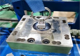
To quantify constraint point reaction forces and provide a quantitative analysis basis for net adjustment, triaxial force sensors (Fig. 6) were selected to measure the reaction forces at each constraint point. These sensors monitor loads in all three directions with an error margin of ≤ 0.5 %, ensuring precise load distribution analysis.
Fig. 6Triaxial force sensors at constraint points
To ensure the restraint net achieves an optimal installation configuration prior to testing, a suitable adjustment method was employed. This configuration ensures that primary load-bearing straps share loads uniformly and collectively transmit forces to the boundary supports, while minimizing experimental result variability when identical test specimens undergo the same test under the same installation conditions. This process provides a basis for validating the net’s installation and operational performance on aircraft.
5. Results comparison
5.1. Failure load comparison
The failure loads of 3 test specimens under the forward load scenario are listed in Table 2.
Analysis of Table 2 shows that the failure loads of the three test specimens were closely aligned, with a maximum coefficient of variation of 3.9 %. This confirms the applicability of the adopted test methodology and techniques for evaluating flexible structures like the restraint net.
Table 2Failure load of test specimens
Test specimen ID | Test scenario | Failure load level (%) | Deviation from average (%) |
Door Net Front 1 | Forward Load | 132.8 | 3.9 |
Door Net Front 2 | Forward Load | 125 | 2.2 |
Door Net Front 3 | Forward Load | 125.8 | 1.6 |
5.2. Failure mode comparison
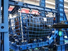
All three restraint nets exhibited identical failure modes: fracture of the mounting base at primary load-bearing strap connection points (the mounting base is fixed to the aircraft structure and is not part of the net structure). This caused the straps to detach from the connection points, indicating that the straps themselves met the design strength requirements. The normal failure mode of the restraint net is shown in Fig. 7.
Fig. 7Normal failure mode of the restraint net
5.3. Constraint loads comparison
The interface loads at primary load-bearing strap connection points during failure are presented in Table 3.
Table 3Interface loads at connection points
Connection point | Load (N) | |||
1st | 2nd | 3rd | Coefficient of variation (CV) | |
P9 | 9750 | 9400 | 9252 | 1.3 % |
P18 | 7311 | 8072 | 7722 | 2.3 % |
P24 | 9171 | 9002 | 8792 | 1.0 % |
P25 | 8354 | 9664 | 9824 | 4.1 % |
Analysis of Table 3 reveals that the interface loads at all primary connection points remained below 10.8 kN during failure, fulfilling the design requirement to protect the air frame structure. The minimal load variation across the three trials demonstrates high test repeatability, validating the universality of the test method.
5.4. Comparison of physical and virtual experiments
In the virtual experiment, a multibody dynamics model of the restraint net was developed using finite element analysis. By applying boundary loads consistent with real cargo scenarios, the simulation predicted a maximum dynamic displacement of 229.5 mm (Table 4). In physical testing, high-precision displacement sensors recorded an actual maximum displacement of 230.1 mm.
The relative error between the two results was only 0.26 %, significantly exceeding the aviation industry’s allowable error threshold for flexible structure validation (≤ 3 %). This confirms that the virtual experiment model accurately predicts the net’s mechanical behavior under extreme conditions, meeting the required model credibility standards.
This validation not only provides a reliable simulation basis for the net’s digital design but also demonstrates the effectiveness of integrating virtual and physical testing methodologies. The precise agreement between simulation and physical results highlights breakthroughs in key technical areas, including boundary condition modeling, material constitutive model selection, and contact algorithm optimization. The outcomes align with design specifications and test requirements.
Table 4Maximum displacement comparison of restraint net center area
Position | Virtual experiment displacement (mm) | Physical experiment displacement (mm) | Error |
748847 | 229.5 | 230.1 | 0.26 % |
6. Conclusions
The experimental results demonstrate that the failure loads of the three test articles showed close agreement, with a maximum coefficient of dispersion (COD) of 3.9 %. Constraint point loads exhibited minimal variability, characterized by a maximum coefficient of variation (COV) of 4.1 %. These statistical metrics validate the applicability of the proposed strength testing methodology for flexible arresting net assemblies. All three test articles displayed identical failure modes, with the load-transfer straps fracturing within their designed strength thresholds. This consistency confirms that the arresting net’s core load-bearing components satisfy structural integrity requirements under ultimate loading conditions.
Prior to this work, the aviation industry lacked validated methods to predict system-level failure of woven restraint nets due to uncharacterized load-path interactions – a limitation decisively overcome by our triaxial monitoring framework.
This project represents the first domestic application of strength validation for restraint nets under specified conditions in China, addressing urgent technical demands. The established “Civil Aircraft Flexible Cargo Hold Restraint Net Strength Testing Technology” forms a complete and rigorous technical system, filling multiple domestic technical gaps. The outcomes have been successfully applied to cargo hold restraint static load development tests and certification tests, providing critical experimental evidence for structural improvements, finalization, and the subsequent compilation of the Restraint Net Installation and Operation Manual. The methodology also serves as a reference for strength verification of similar flexible structures, demonstrating significant economic and social value.
References
-
J. Zhao, “Research on design and airworthiness verification of C919 cargo blocking network fixing device,” Nanjing University of Aeronautics and Astronautics, 2019.
-
J. Hu, “Research on design and compliance verification of a type of aircraft arresting net,” Nanjing University of Aeronautics and Astronautics, 2019.
-
X. Zhu, Y. Feng, and X. Xue, “Nonlinear finite element modeling and analysis of cargo restraint net for a transport aircraft,” Mechanical Science and Technology, Vol. 3, pp. 460–464, 2014.
-
T. Ye, “Finite element analysis guide for aeronautical structures,” Aviation Industry Press, Beijing, China, 1996.
-
X. Jin, Y. Liu, and Y. Liu, “Simulation study on landing impact characteristics of carrier-based aircraft restraint net,” Computer Simulation, Vol. 5, pp. 27–31, 2021.
-
X. Zhao, “Simulation study on impact characteristics of cargo restraint net for transport aircraft,” Aeronautical Science and Technology, Vol. 6, pp. 18–21, 2014.
-
W. Huang, Q. Wang, and X. Zhao, “Force analysis of restraint net under external loads,” Ship Engineering, Vol. 6, pp. 114–118, 2020.
About this article

The authors have not disclosed any funding.
The datasets generated during and/or analyzed during the current study are available from the corresponding author on reasonable request.
The authors declare that they have no conflict of interest.
