Abstract
With the rapid development of construction industrialization, modular construction has been widely applied due to its advantages such as high efficiency and environmental friendliness. As the core hoisting equipment, the crane hoisting system faces issues like poor stability and low intelligence, which have become key technical bottlenecks restricting construction efficiency. To address the above problems, this study aims at the anti-swing control of the lifting and traveling mechanism, and establishes a dynamic model of the lifting and traveling mechanism with a double-pendulum effect. Based on this model, a nonlinear model predictive controller (NMPC) is designed, followed by simulation analysis and experimental verification. The simulation results show that the designed controller can effectively suppress the load swing during the movement of the trolley (the tilt angle is controlled within ±1°) and exhibits good robustness under different working conditions. In addition, by building a scaled-down experimental platform, the accuracy of the simulation model and the actual performance of the controller are further verified. This research provides an efficient and accurate hoisting solution for improving the precision and efficiency of tower crane systems in modular building construction, and is of great significance for promoting the development of modern construction technology.
Highlights
- A dynamic model of the double-pendulum lifting and traveling mechanism considering practical engineering characteristics is established, addressing the nonlinear and underactuated nature of crane hoisting systems.
- An NMPC controller is designed, which predicts load swing trends in advance and dynamically adjusts control strategies, outperforming traditional PD control in stability and accuracy.
- Simulation and experimental results confirm that the NMPC controller strictly restricts the load tilt angle within ±1°, achieves millimeter-level positioning accuracy, and maintains strong robustness under varying working conditions.
- The scaled-down experimental platform validates the simulation model’s accuracy, with inclination angle errors (3.9%-17.3% RMS, 1.75%-13.5% maximum) meeting engineering expectations, demonstrating practical application value.
1. Introduction
With the continuous development of modular construction technology, the precision and efficiency of module hoisting have become increasingly important. As the core hoisting equipment, the crane hoisting system is widely used in the hoisting and precise placement of building modules. However, issues such as poor stability and low intelligence have become key technical bottlenecks restricting construction efficiency. During the hoisting process, the swing effect of the platform will cause deviations in module positioning, affecting installation accuracy and efficiency. In addition, due to the poor shear resistance of concrete modules, excessive swing amplitude during hoisting may easily lead to uneven stress and cracking of the modules. Therefore, how to effectively suppress platform swing and accurately adjust the pose of the grabbing platform has become a key technical issue to improve the installation accuracy and efficiency of modular buildings.
Current research in crane swing control focuses on single-pendulum systems. For instance, Le et al. [1] developed robust controllers combining feedback linearization and sliding mode control, while Ramli et al. [2] applied predictive control with adaptive feedback to reduce payload swing. Takahashi et al. [3] adopted a smooth acceleration/ deceleration cycloidal trajectory planning method that considered both payload swing and boom torsion dynamics. Lu et al. [4] developed a full-state feedback based trajectory modification approach combined with Lyapunov stability theory, proving the system's asymptotic stability. Despite these efforts, practical crane systems often exhibit double-pendulum dynamics (hook-trolley and load-hook oscillations) [5], rendering traditional single-pendulum methods inadequate.
Recent advances in double-pendulum crane control address critical challenges: Ouyang Huimin et al. [6] introduced online trajectory planning for robustness under disturbances, while Lu Biao et al. [7] proposed a dual-degree-of-freedom scheme incorporating elastic deformation. Sun Zheng et al. [8] developed adaptive fuzzy control to suppress oscillations in distributed-mass-beam systems, and He Chen et al. [9] solved emergency braking via coupling-enhanced methods. Contributions include Miao Xiaodong et al. [10] adaptive backstepping controller, Huang Jie et al. [11] command smoothing for oscillation reduction, and Wu Qingxiang et al. [12] dynamics model with rope-length adaptability. Bello et al. [13] further validated the impact of rope length and load parameters on system behavior.
Traditional control methods (such as PD control and sliding mode control) often have problems such as insufficient control accuracy and response delay when dealing with complex nonlinear dynamics and underactuated characteristics, making it difficult to meet the requirements of high-precision hoisting. Model Predictive Control (MPC) stands out for its ability to handle multi-variable constraints, optimize inputs, and adapt to uncertainties [14-16]. Its success in robotics and aerospace [17-19] highlights its potential for crane systems. This study proposes a nonlinear MPC (NMPC) framework tailored for double-pendulum hoisting mechanisms. By integrating cable flexibility dynamics into the system model, the method enhances pose control accuracy and stability through real-time input optimization.
This study proposes a Model Predictive Control (NMPC) method based on a complex double-pendulum lifting and traveling mechanism. By optimizing control inputs in real time and considering the flexible characteristics of cables, the platform swing is suppressed and the stability of pose control is improved. Through analyzing the flexible dynamic model of the tower crane’s cables, the mathematical model of the system is constructed, and the corresponding NMPC controller is designed.
2. Dynamic modeling of the lifting and traveling mechanism
In practical engineering, the movement of overhead cranes is subject to numerous disturbances, such as uneven friction coefficients caused by track issues, height differences resulting from aging track joints, and environmental factors like wind resistance. These uncontrollable disturbance terms greatly increase the complexity of deriving the dynamic model of the grabbing platform. Therefore, to accurately describe the operating laws of the overhead crane and the grabbing platform, and under the premise of not losing generality, the dynamic model usually adopts the following assumptions to facilitate controller design and stability analysis: the working environment and the crane's own mechanical conditions are assumed to be in an ideal state, and the steel ropes of the double-pendulum lifting and traveling mechanism are regarded as massless rigid links; thus, their flexibility, torsion, and nonlinear factors such as friction are not considered [20-24].
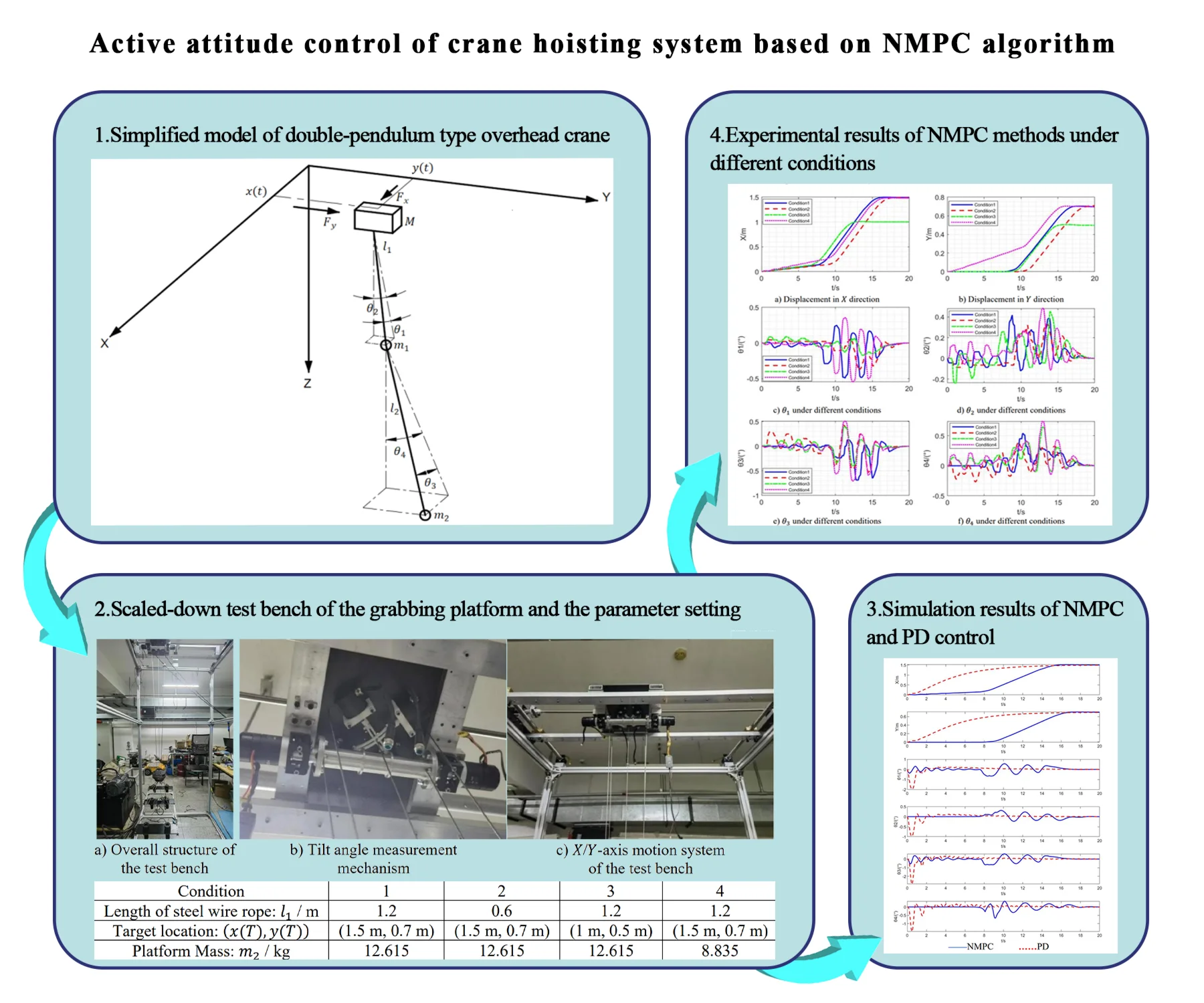
Under these assumptions, the system is simplified to an idealized double-pendulum 3D spatial model, as illustrated in Fig. 1. The model comprises three simplified mass blocks (trolley, hook block, and lifting platform), rigid links representing steel cables, and a simplified structural frame. This abstraction reduces the tower crane lifting system to a double-pendulum 3D spatial model for analytical tractability.
The meanings of the parameters in the figure 1 are as follows: is the mass of the crane, is the mass of the hook, is the mass of the grabbing platform and its load, is the length of the lifting steel cable, is the length from the center of the grabbing platform to the hook, is the gravitational acceleration; , is the crane displacement in the and directions; is the -direction component of the hook’s steel cable tilt angle, is the -direction component of the hook’s steel cable tilt angle, is the -direction component of the grabbing platform's steel cable tilt angle, is the -direction component of the grabbing platform’s steel cable tilt angle.
Fig. 1Simplified model of double-pendulum type overhead crane
The first step is to establish the dynamic model of the overhead crane hoisting system with a double pendulum effect [25-27]. Fig. 1 shows a simplified schematic of the double-pendulum grabbing platform. From Fig. 1, the velocity vectors of the crane, hook, and grabbing platform can be derived as follows:
where, is an abbreviation for , is an abbreviation for .
The kinetic and potential energy equations of the lifting and traveling mechanism are established with respect to the initial position of the grabbing platform as the reference point for zero potential energy:
Based on the Lagrangian energy equation, the following can be derived:
Among them, , . , and are coefficients related to friction. is the state vector, , is the inertia matrix. is the centripetal-Coriolis matrix, is the control vector, is the gravitational vector. The detailed expression for , , , and are presented in the Appendix.
To design the controller, the state-space equations of the grabbing platform system are required. The state vector for the state-space equations is introduced as follows: . Based on the Lagrangian Eq. (12) of the grabbing platform system, the state-space equations of the grabbing platform system are derived as follows:
3. Stable control of the lifting and traveling mechanism
3.1. Control objectives of the lifting and traveling mechanism
The control objective of stable movement is to enable the overhead crane to reach the target position from the initial position stably, quickly and accurately within the set time , while eliminating the residual angle of the steel rope tilt angle; during the movement of the overhead crane, the tilt angles of the hook and the grabbing platform should be suppressed. The design of the controller needs to satisfy the basic movement constraints of the overhead crane [28-29], which are:
The crane drives to the set position:
Residual angle Elimination for Hoisting Cables:
To ensure the stability of the suspended load, the swinging angle of the steel cable should be limited to a certain range during the movement:
where, is the maximum allowable value for the swinging angle in the and directions.
During the motion, due to power limitations, the crane’s speed must be restricted to a certain range:
where, is the maximum allowable values for the crane’s speed in the and directions.
3.2. Design of NMPC controller
Model Predictive Control (MPC) can handle various constraint issues, such as control input constraints, state constraints, and output constraints. Through rolling optimization and feedback correction, it exhibits good robustness [14]. A controller based on a nonlinear model predictive controller is designed for the overhead crane system. Due to the underactuated characteristics of the crane system, load swinging can be eliminated by joint motion control of the crane and the hoisting rope [30].
The NMPC optimal control optimization function is:
where, is the state variable, denotes the optimal trajectory, represents the control input, is the optimal control, , defines the constraint, is the initial state, and are the weighting coefficients for the state and control terms, respectively.
Define the system function :
Since Eq. (14) is identically zero, the choice of (including its substitution into the objective function) has no effect on the result:
The Hamiltonian function is defined as:
Substituting into the objective function yields:
When the optimal control is applied, the cost functional is minimized:
Set , , .
By expanding the Hamiltonian function via a Taylor series and integrating, we obtain:
The value of does not influence the result. For computational simplicity, , is set. The initial value introduces no error, with . Substituting these into Eqs. (19) and (20), we obtain:
where, is a coefficient (which can be positive or negative) and denotes the disturbance.
To achieve the optimal solution, the condition must be satisfied, requiring:
The state transition matrix was derived by solving the Riccati equation.
The continuous-time controller was discretized by partitioning the time horizon into intervals with a system period . The system dynamics were discretized as follows:
where, , .
Substituting the state transition matrix into Eq. (23) yields:
where, denotes the steady-state solution of the Riccati equation, derived by solving the discrete-time Riccati equation:
The controller equations are solved and iterated using the fourth-order Runge-Kutta method [31]:
4. Simulation analysis on stable movement of the lifting and traveling mechanism
4.1. Stability verification
For the crane system, research on its stability mainly focuses on the load tilt angle in underactuated control. The Lyapunov direct method for determining system stability requires the construction of an energy function; based on the established dynamic equation of the grabbing platform, the non-negative scalar energy function for the Lyapunov direct method is constructed as follows:
Since : state weight matrix (positive definite), : control variable weight matrix (positive definite), it follows that ≥ 0, and = 0 if and only if and .
Taking the time derivative of , combining the system state-space equation with the NMPC optimal control law, and leveraging the rolling optimization characteristic of NMPC, the optimal control law is derived through the construction of the Hamiltonian function and the Lagrange multiplier method:
where is the discretization coefficient of the input matrix, and is the steady-state positive definite solution of the discrete Riccati equation. Substituting the optimal control law into and combining the properties of 0, > 0, and > 0, it can be proven that:
When = 0, it is certain that . According to LaSalle’s Invariance Principle, the system converges to the desired steady state.
4.2. Simulation of the lifting and traveling mechanism
To validate the control performance of the proposed nonlinear model predictive controller, system modeling, simulation and analysis of the lifting and traveling mechanism were conducted using MATLAB. Parameters of the lifting and traveling mechanism, configured based on the designed experimental platform dimensions, are listed in Table 1.
Table 1Parameters of the lifting and traveling mechanism
Name | Symbol | Numerical value | Unit |
Crane mass | 4.55 | kg | |
Hook mass | 4.78 | kg | |
Lifting platform and load mass | 12.615 | kg | |
Hoisting rope length | 1.2 | m | |
Grabbing platform rope length | 0.3 | m |
At the initial position (), the initial state parameters of the grabbing platform are set as: , . The initial input values are set as: .
According to control objectives (1) and (2), at the target position (), the crane’s transnational position target values in the and directions are: 1.5 m, 0.7 m. The desired value for the grabbing platform's swinging angle is: .
According to control objectives (3) and (4), during the movement, to ensure the stability of both the crane and the load, the desired constraint value for the grabbing platform's swinging angle is set as 1°, ±1°, ±1°, ±1°, ±1°. The motion constraints for the crane are set as follows: 0.2 m/s, 0.1 m/s. The force constraints in the and directions for the crane are set to 20 N.
The dynamic model of the tower crane lifting system was developed in MATLAB. The ParNMPC toolbox was employed to design an NMPC controller for model simulation and analysis. Key simulation parameters include: discrete grid points: 400, prediction horizon: 20, simulation duration: 20 s.
The optimization function parameters were weighted according to state variable importance. Given the primary control objectives of precise crane positioning and maintaining platform stability during motion: control parameter weight matrix: , state parameter weight matrix: .
Meanwhile, to verify the performance of the method proposed in this paper, the PD control method is selected for comparison. The control law of the PD method is as follows:
where: and are the displacement errors in the and directions, respectively; and are the trolley speeds in the and directions, respectively; and are the combined errors:
During simulation, the values are set as follows: 5, 20, 5, 20, 10, 3, 10, 3.
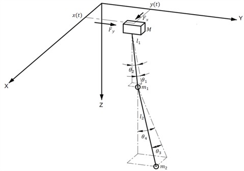
The simulation results are shown in Fig. 2 and Table 2.
Fig. 2Simulation result diagram
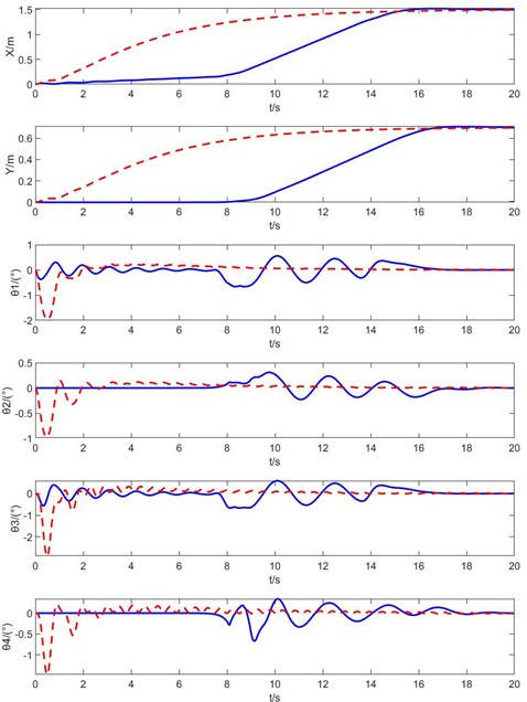

Table 2Comparison of performance indicators
indicator | ||||
Tilt RMS of NMPC method | 0.2506 | 0.1032 | 0.2697 | 0.1402 |
Tilt RMS of Pd method | 0.3217 | 0.1535 | 0.3720 | 0.1894 |
Maximum tilt angle of NMPC method (°) | 0.6642 | 0.3088 | 0.6656 | 0.6667 |
Maximum tilt angle of Pd method (°) | 1.9665 | 0.9732 | 2.9002 | 1.4676 |
Analysis of the simulation results shows that compared with PD control, nonlinear model predictive control (NMPC) has core advantages in two aspects: swing suppression effect and motion smoothness. NMPC can optimize control inputs in real time, predict the load swing trend in advance and adjust dynamically, making the peak values of steel rope tilt angles , , , significantly lower than those of PD control (as shown in Table 3, the tilt angles under NMPC control are all ≤ 1°, while the maximum peak tilt angle under PD control reaches 2.9°). In addition, when the trolley moves, NMPC can plan a motion trajectory of “slow acceleration - constant speed - slow deceleration” to avoid impulsive speed changes during the start-stop phase. However, PD control is prone to speed fluctuations at the start of motion due to fixed parameters, which indirectly causes large-amplitude swing of the load. In terms of trolley positioning, the displacement error of the trolley in the direction under NMPC control is 3.1 mm, and the displacement error in the direction is 2.2 mm. The positioning accuracy reaches the millimeter level, which meets the module positioning requirements.
Comprehensive analysis of the simulation results shows that the tilt angles of the grabbing platform and hook during the trolley’s movement are within a reasonable range, and the positioning accuracy error of the trolley trajectory is less than 0.5 %. This indicates that the positioning of the trolley trajectory is relatively accurate and the grabbing platform and load can be kept stable during the movement process.
4.3. Simulation of the lifting and traveling mechanism under different working conditions
During the motion of the dual-rail lifting and traveling mechanism, variations in payload mass, cable length, and trolley target position can significantly affect trolley positioning accuracy, as well as oscillations of the grabbing platform and payload [32]. To evaluate the impact of different parameters on the control system, the following four sets of comparative simulations were conducted. The changed system parameters are shown in Table 3.
Table 3The parameter settings of the lifting and traveling mechanism
Condition | 1 | 2 | 3 | 4 |
Length of steel wire rope: / m | 1.2 | 0.6 | 1.2 | 1.2 |
Target location: | (1.5 m, 0.7 m) | (1.5 m, 0.7 m) | (1 m, 0.5 m) | (1.5 m, 0.7 m) |
Platform Mass: / kg | 12.615 | 12.615 | 12.615 | 8.835 |
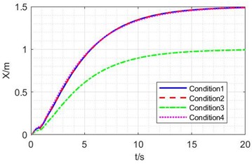
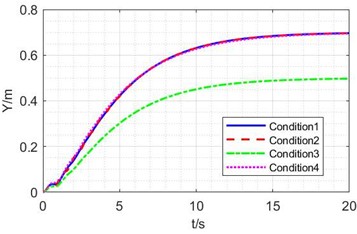
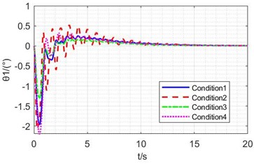
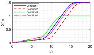
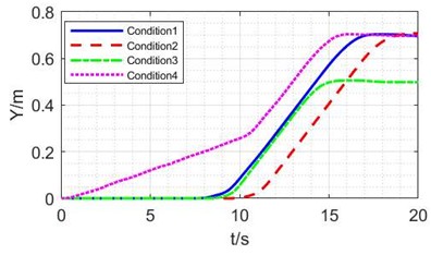
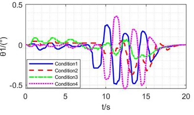
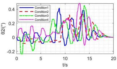
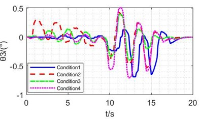
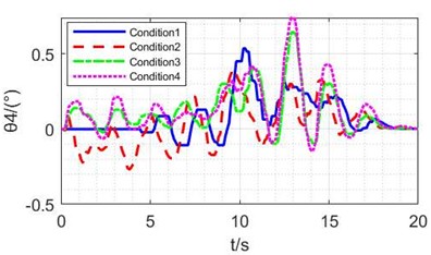
Fig. 3Simulation results of NMPC methods under different conditions
a) Displacement in direction
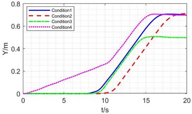
b) Displacement in direction
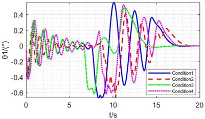
c) under different conditions
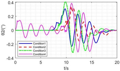
d) under different conditions
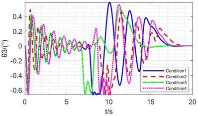
e) under different conditions
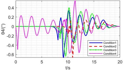
f) under different conditions
Fig. 4Simulation results of PD methods under different conditions
a) Displacement in direction
b) Displacement in direction
c) under different conditions
d) under different conditions
e) under different conditions
f) under different conditions
Table 4Comparison of performance indicators
Condition | 1 | 2 | 3 | 4 |
Angle RMS of NMPC method | 0.3039 | 0.2330 | 0.2639 | 0.3265 |
angle RMS of Pd method | 0.6563 | 0.9659 | 0.4428 | 0.7839 |
Maximum angle of NMPC method (°) | 0.8664 | 0.6886 | 0.6559 | 0.8151 |
Maximum angle of Pd method (°) | 3.2484 | 4.1019 | 2.1974 | 3.8162 |
The overhead crane system was simulated under four distinct operational scenarios, and the comparative analysis of the simulation results is illustrated in Figs. 3, 4 and Table 4.
To further analyze the inclination angle of the grabbing platform, the spatial inclination angle of the grabbing platform is obtained by means of the tilt angles and of the steel wire ropes. The root mean square (RMS) values and maximum values of the spatial inclination angles of the grabbing platform under different working conditions for the two control methods are obtained. The calculation results and the positioning error of the crane are shown in Table 4.
Analysis of the data in Figs. 3, 4 and Table 4 shows that under the NMPC control method, the displacement errors in the and directions for working conditions 1, 2, 3, and 4 are less than 1 cm, and the residual angles are within ±0.1°. Moreover, in the simulation results of all working conditions, the tilt angle of the steel wire rope is controlled within 1°, with high positioning accuracy and basically eliminated residual angles. This proves that compared with the traditional PD control method, the NMPC control method has strong robustness.
5. Experimental verification
5.1. Design and construction of the test bench
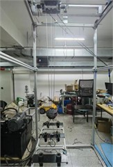
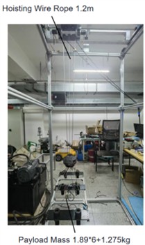
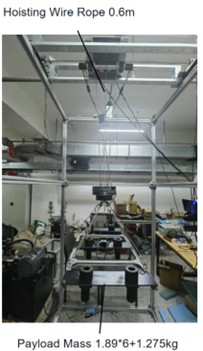
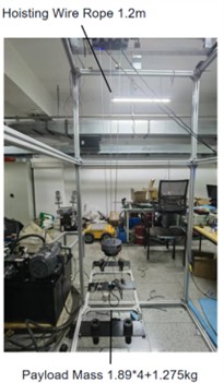
This study designed a test bench using geometric similarity principles to develop an equivalent scaled model of the actual grabbing platform, with a 1:11 scaling ratio resulting in platform dimensions of approximately 850 mm×400 mm constructed from assembled profile angle iron. The platform incorporates fiberglass panels below for mounting adjustable counterweights to conduct various working condition tests and eccentricity balancing experiments. The main frame structure replicates the translational motion mechanism of overhead crane trolleys and girders, with the outer framework built from profile angle iron considering laboratory constraints and cost limitations, featuring specific dimensions in the , , and directions, as shown in the 3D structural diagram in Fig. 5.
Fig. 5Scaled-down test bench of the grabbing platform
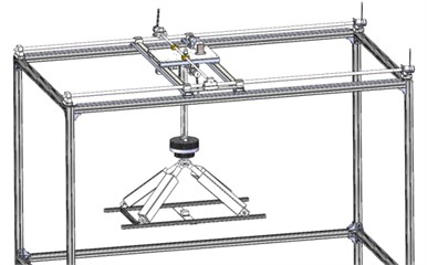
Fig. 6Test bench assembly
a) Overall structure of the test bench
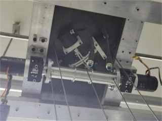
b) Tilt angle measurement mechanism
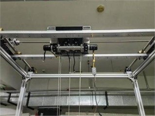
c)/-axis motion system of the test bench
Based on the 3D structure shown in Fig. 6, the experimental test bench was constructed as presented in Fig. 6.
5.2. Experimental verification under different working conditions
The motion stability experiment of grabbing platform involves driving the trolley through motors to move the grabbing platform below, simulating the process of the overhead crane moving construction modules. The experiment consists of two parts: driving the gantry and trolley movement via /-direction motors, and measuring both the wire rope tilt angles and trolley displacement data.
Based on the grabbing platform motion system structure shown in Fig. 6, the stability experiment procedure includes: inputting the simulated crane velocity and displacement curves into drive motors to move the gantry and trolley, while laser distance sensors measure /-direction displacements during platform movement, and the measurement structure with two orthogonal rotary encoders measures the central wire rope tilt angles, which are converted to determine the platform’s /-direction tilt angles. The experimental conditions for different working conditions are shown in Fig. 7.
Fig. 7Experimental for different conditions
a) Working conditions 1 and 3 parameters
b) Working conditions 2 parameters
c) Working conditions 4 parameters
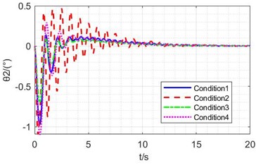
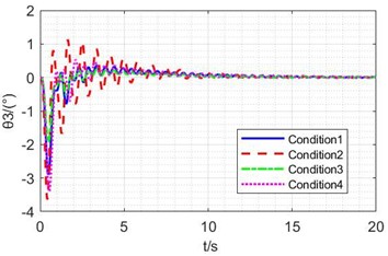
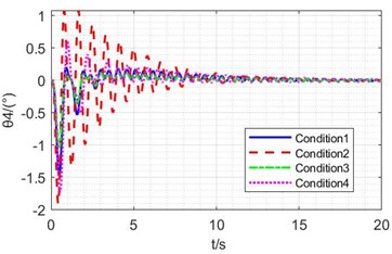
The grabbing platform of the test bench follows the controller’s planned motion trajectory, during which rotary encoders acquire wire rope tilt angle data. This data is processed to determine the wire rope deflection angles under different working conditions. Simultaneously, displacement sensors measure the crane’s travel distance along the and axes. After data processing, the crane’s displacements in both and directions are obtained, as illustrated in Fig. 8 and Table 5.
Table 5Comparison of performance indicators between experiment and simulation
Condition | 1 | 2 | 3 | 4 |
RMS in experiment | 0.2513 | 0.2486 | 0.2270 | 0.3137 |
RMS errors (%) | 17.3 | 6.7 | 14.0 | 3.9 |
Maximum angle in experiment (°) | 0.7491 | 0.6177 | 0.6674 | 0.8856 |
Maximum angle Errors (°) | 13.5 | 10.3 | 1.75 | 8.6 |
It can be seen from the experimental results that in the 4 groups of experiments, the displacement curves are consistent with the simulation results. Both in simulation and experiment, the NMPC controller can strictly control the tilt angle of the grabbing platform within ±1°, which meets the requirements of modular construction for load stability.
As shown in Table 5, there are certain errors between the experimental results and the simulation results, which are caused by various factors. First, due to the limitations of the hardware conditions of the experimental platform itself, the motor has mechanical clearance and moment of inertia during rotation, which will affect the control accuracy; in addition, the platform itself inevitably has vibration, and the slight unevenness of the track will cause disturbances to the movement and tilt angle of the grabbing platform, thereby affecting the control accuracy and interfering with the measurement results.
In general, the RMS error of the inclination angle between the experimental and simulation results is 3.9-17.3 %, and the error of the maximum inclination angle is 1.75-13.5 %. Despite these errors, in terms of the overall control effect and trend, the experimental results still have good consistency with the simulation results. This indicates that the simulation model can relatively accurately reflect the characteristics of the actual system, and the designed NMPC controller can also effectively control the tilt angle of the grabbing platform in practical applications, meeting the requirements of modular construction for load stability. At the same time, these errors also reflect the differences between the actual experimental environment and the ideal simulation environment. In the future, aiming at the hardware limitations and external disturbance factors in the experiment, the experimental platform or control algorithm can be further optimized to reduce errors and improve control accuracy.
Fig. 8Experimental results of NMPC methods under different conditions
a) Displacement in direction
b) Displacement in direction
c) under different conditions
d) under different conditions
e) under different conditions
f) under different conditions
6. Conclusions
This paper addresses the technical bottlenecks (poor stability, low intelligence, and insufficient positioning accuracy) of crane hoisting systems in modular building construction, focuses on the active pose control of the lifting and traveling mechanism, and proposes a solution based on a Nonlinear Model Predictive Controller (NMPC). The main research conclusions are as follows:
A dynamic model of the double-pendulum lifting and traveling mechanism with actual engineering characteristics is constructed, and an NMPC controller suitable for its nonlinear underactuated characteristics is designed. Compared with traditional PD control, this controller can predict the load swing trend in advance and adjust the control strategy dynamically, effectively solving the shortcomings of PD control in terms of stability and accuracy.
Simulation and experimental results show that under various working conditions, the trolley positioning error under NMPC control is less than 1 cm, the load tilt angle is strictly controlled within ±1°, and the root mean square (RMS) value of the tilt angle is reduced by approximately 40 %-75 % compared with PD control.
Good robustness is maintained under different steel rope lengths, load masses, and target positions. The results of the scaled-down experimental platform are consistent with the simulation trend, and the errors meet expectations (RMS error of inclination angle: 3.9-17.3 %, maximum inclination angle error: 1.75-13.5 %), which further verifies the accuracy of the dynamic model and the practical engineering value of the controller.
References
-
T. A. Le, V.-H. Dang, D. H. Ko, T. N. An, and S.-G. Lee, “Nonlinear controls of a rotating tower crane in conjunction with trolley motion,” Proceedings of the Institution of Mechanical Engineers, Part I: Journal of Systems and Control Engineering, Vol. 227, No. 5, pp. 451–460, Apr. 2013, https://doi.org/10.1177/0959651812472437
-
L. Ramli, Z. Mohamed, M. Efe, I. M. Lazim, and H. I. Jaafar, “Efficient swing control of an overhead crane with simultaneous payload hoisting and external disturbances,” Mechanical Systems and Signal Processing, Vol. 135, p. 106326, Jan. 2020, https://doi.org/10.1016/j.ymssp.2019.106326
-
H. Takahashi et al., “Sensor-less and time-optimal control for load-sway and boom-twist suppression using boom horizontal motion of large cranes,” Automation in Construction, Vol. 134, p. 104086, Feb. 2022, https://doi.org/10.1016/j.autcon.2021.104086
-
Z. Tian, L. Yu, H. Ouyang, and G. Zhang, “Swing suppression control in tower cranes with time-varying rope length using real-time modified trajectory planning,” Automation in Construction, Vol. 132, p. 103954, Dec. 2021, https://doi.org/10.1016/j.autcon.2021.103954
-
B. Lu, Y. Fang, and N. Sun, “Enhanced-coupling adaptive control for double-pendulum overhead cranes with payload hoisting and lowering,” Automatica, Vol. 101, pp. 241–251, Mar. 2019, https://doi.org/10.1016/j.automatica.2018.12.009
-
H. Ouyang, Z. Tian, L. Yu, and G. Zhang, “Adaptive tracking controller design for double-pendulum tower cranes,” Mechanism and Machine Theory, Vol. 153, p. 103980, Nov. 2020, https://doi.org/10.1016/j.mechmachtheory.2020.103980
-
M. Thomas, T. Englert, and O. Sawodny, “Model-based velocity-tracking-control of self-erecting industrial tower cranes,” Control Engineering Practice, Vol. 147, p. 105928, Jun. 2024, https://doi.org/10.1016/j.conengprac.2024.105928
-
Z. Sun and H. Ouyang, “Adaptive fuzzy tracking control for vibration suppression of tower crane with distributed payload mass,” Automation in Construction, Vol. 142, p. 104521, Oct. 2022, https://doi.org/10.1016/j.autcon.2022.104521
-
H. Chen, M. Li, and Y. Wu, “An emergency braking method with swing suppression and safety limits consideration for double pendulum cranes,” Control Engineering Practice, Vol. 139, p. 105638, Oct. 2023, https://doi.org/10.1016/j.conengprac.2023.105638
-
X. Miao, H. Zhu, S. Li, X. Xu, H. Ouyang, and H. Xi, “Adaptive-back-stepping-based controller design for double-pendulum rotary cranes,” ISA Transactions, Vol. 136, pp. 676–686, May 2023, https://doi.org/10.1016/j.isatra.2022.11.011
-
J. Huang, Z. Liang, and Q. Zang, “Dynamics and swing control of double-pendulum bridge cranes with distributed-mass beams,” Mechanical Systems and Signal Processing, Vol. 54-55, pp. 357–366, Mar. 2015, https://doi.org/10.1016/j.ymssp.2014.09.005
-
Q. Wu, X. Wang, L. Hua, and M. Xia, “Modeling and nonlinear sliding mode controls of double pendulum cranes considering distributed mass beams, varying roped length and external disturbances,” Mechanical Systems and Signal Processing, Vol. 158, p. 107756, Sep. 2021, https://doi.org/10.1016/j.ymssp.2021.107756
-
M. M. Bello, Z. Mohamed, M. Efe, and H. Ishak, “Modelling and dynamic characterisation of a double-pendulum overhead crane carrying a distributed-mass payload,” Simulation Modelling Practice and Theory, Vol. 134, p. 102953, Jul. 2024, https://doi.org/10.1016/j.simpat.2024.102953
-
J. J. Yao, Y. K. Zhang, and Y. Ke, “Research on robot attitude control strategy based on model predictive control,” (in Chinese), Journal of Mechanical Engineering, Vol. 60, No. 19, p. 88, Jan. 2024, https://doi.org/10.3901/jme.2024.19.088
-
Z. K. Yang, S. H. Li, and Z. F. Wang, “Trajectory tracking control of distributed drive intelligent vehicles based on adaptive variable-parameter MPC,” (in Chinese), Journal of Mechanical Engineering, Vol. 60, No. 6, pp. 363–377, 2024.
-
Z. Y. Zou et al., “Research status and development trend of nonlinear model predictive control technology,” (in Chinese), Computers and Applied Chemistry, Vol. 35, No. 1, pp. 7–17, 2018, https://doi.org/10.16866/j.com.app.chem201801002
-
G. R. Zhao, J. F. Gai, and Z. G. Hu, “Research progress of nonlinear model predictive control,” (in Chinese), Journal of Naval Aeronautical and Astronautical University, Vol. 29, No. 3, pp. 201–208, 2014.
-
D. F. He, B. C. Ding, and S. Y. Yu, “Review of several basic characteristics and themes of model predictive control for nonlinear systems,” (in Chinese), Control Theory and Applications, Vol. 30, No. 3, pp. 273–287, 2013.
-
S. H. Xu, Q. X. Sun, and W. J. Gu, “Overview of model methods for nonlinear predictive control,” (in Chinese), Journal of Naval Aeronautical and Astronautical University, No. 6, pp. 633–636, 2007.
-
D. Jolevski and O. Bego, “Model predictive control of gantry/bridge crane with anti-sway algorithm,” Journal of Mechanical Science and Technology, Vol. 29, No. 2, pp. 827–834, Feb. 2015, https://doi.org/10.1007/s12206-015-0144-8
-
Z. Wu, X. Xia, and B. Zhu, “Model predictive control for improving operational efficiency of overhead cranes,” Nonlinear Dynamics, Vol. 79, No. 4, pp. 2639–2657, Dec. 2014, https://doi.org/10.1007/s11071-014-1837-8
-
D. Schindele and H. Aschemann, “Fast nonlinear MPC for an overhead travelling crane,” IFAC Proceedings Volumes, Vol. 44, No. 1, pp. 7963–7968, Jan. 2011, https://doi.org/10.3182/20110828-6-it-1002.03510
-
J. J. Sun, L. Chai, and Q. H. Guo, “Neural network sliding mode control of overhead cranes under three-dimensional motion mode,” (in Chinese), Control Theory and Applications, Vol. 41, No. 11, pp. 2071–2079, 2024.
-
Z. Liu, Z. Lin, and M. Wu, “Study of anti-swing control of ship cranes based on time delay feedback,” Journal of Vibroengineering, Vol. 23, No. 4, pp. 1034–1055, Jun. 2021, https://doi.org/10.21595/jve.2021.21697
-
O. Huimin, B. Zhao, and G. Zhang, “Swing reduction for double‐pendulum three‐dimensional overhead cranes using energy‐analysis‐based control method,” International Journal of Robust and Nonlinear Control, Vol. 31, No. 9, pp. 4184–4202, Mar. 2021, https://doi.org/10.1002/rnc.5466
-
N. Ji, J. Liu, and X. Xing, “Modeling and vibration control for a nonlinear three‐dimensional flexible moving string system with input quantization and event‐triggering,” International Journal of Robust and Nonlinear Control, Vol. 33, No. 3, pp. 2336–2356, Nov. 2022, https://doi.org/10.1002/rnc.6505
-
B. Yan, H. Lin, C. Cai, and P. Shi, “An enhanced coupling nonlinear control for quadrotor with suspended double‐pendulum payload,” International Journal of Robust and Nonlinear Control, Vol. 34, No. 14, pp. 9676–9696, Sep. 2024, https://doi.org/10.1002/rnc.7483
-
M. Zhang, Y. Zhang, B. Ji, C. Ma, and X. Cheng, “Modeling and energy-based sway reduction control for tower crane systems with double-pendulum and spherical-pendulum effects,” Measurement and Control, Vol. 53, No. 1-2, pp. 141–150, Nov. 2019, https://doi.org/10.1177/0020294019877492
-
H. Ouyang, Z. Tian, L. Yu, and G. Zhang, “Motion planning approach for payload swing reduction in tower cranes with double-pendulum effect,” Journal of the Franklin Institute, Vol. 357, No. 13, pp. 8299–8320, Sep. 2020, https://doi.org/10.1016/j.jfranklin.2020.02.001
-
H. Deng and T. Ohtsuka, “A highly parallelizable newton-type method for nonlinear model predictive control,” IFAC-PapersOnLine, Vol. 51, No. 20, pp. 349–355, Jan. 2018, https://doi.org/10.1016/j.ifacol.2018.11.058
-
H. Deng and T. Ohtsuka, “A parallel Newton-type method for nonlinear model predictive control,” Automatica, Vol. 109, p. 108560, Nov. 2019, https://doi.org/10.1016/j.automatica.2019.108560
-
J. H. Liu et al., “Neural network sliding mode control for double-pendulum overhead cranes with input saturation,” (in Chinese), Control Engineering of China, Vol. 31, No. 4, pp. 687–694, 2024, https://doi.org/10.14107/j.cnki.kzgc.20220039
About this article

Financial support for this work was provided by the National Key Research and Development Program of China(2023YFC3806603).
The datasets generated during and/or analyzed during the current study are available from the corresponding author on reasonable request.
Chun Jin: conceptualization, funding acquisition, investigation, project administration, resources, supervision. Shuo Qian: data curation, formal analysis, investigation, methodology, software, validation, visualization, writing-original draft preparation, writing-review and editing. Zhenyu Wang: data curation, formal analysis, investigation, methodology, software, validation, visualization, writing-review and editing. Chunyu Tian: funding acquisition, resources, supervision. Yanjiang Su: funding acquisition, resources, supervision. Shengyu Zhou: data curation, software. Yanhua Shen: conceptualization, formal analysis, investigation, methodology, writing-original draft preparation.
The authors declare that they have no conflict of interest.
