Abstract
The problem of optimizing the drive design parameters for a high-speed linear system is solved based on minimizing the inertial torque. New analytical expressions are obtained for determining the optimal gear ratio of the intermediate transmission, taking into account the moments of inertia of rotating masses, the carriage mass, and the screw pitch. An optimization problem is proposed to determine the number of gear teeth and the screw pitch by minimizing a function that includes the relative error between the actual and calculated gear ratio, as well as the total number of teeth required to ensure the specified travel speed of a carriage. At the next calculation stage, the number of gear teeth is refined based on the nearest standard screw pitch values. The resulting parameters are evaluated using a transient dynamic analysis according to key kinematic and energy characteristics.
Highlights
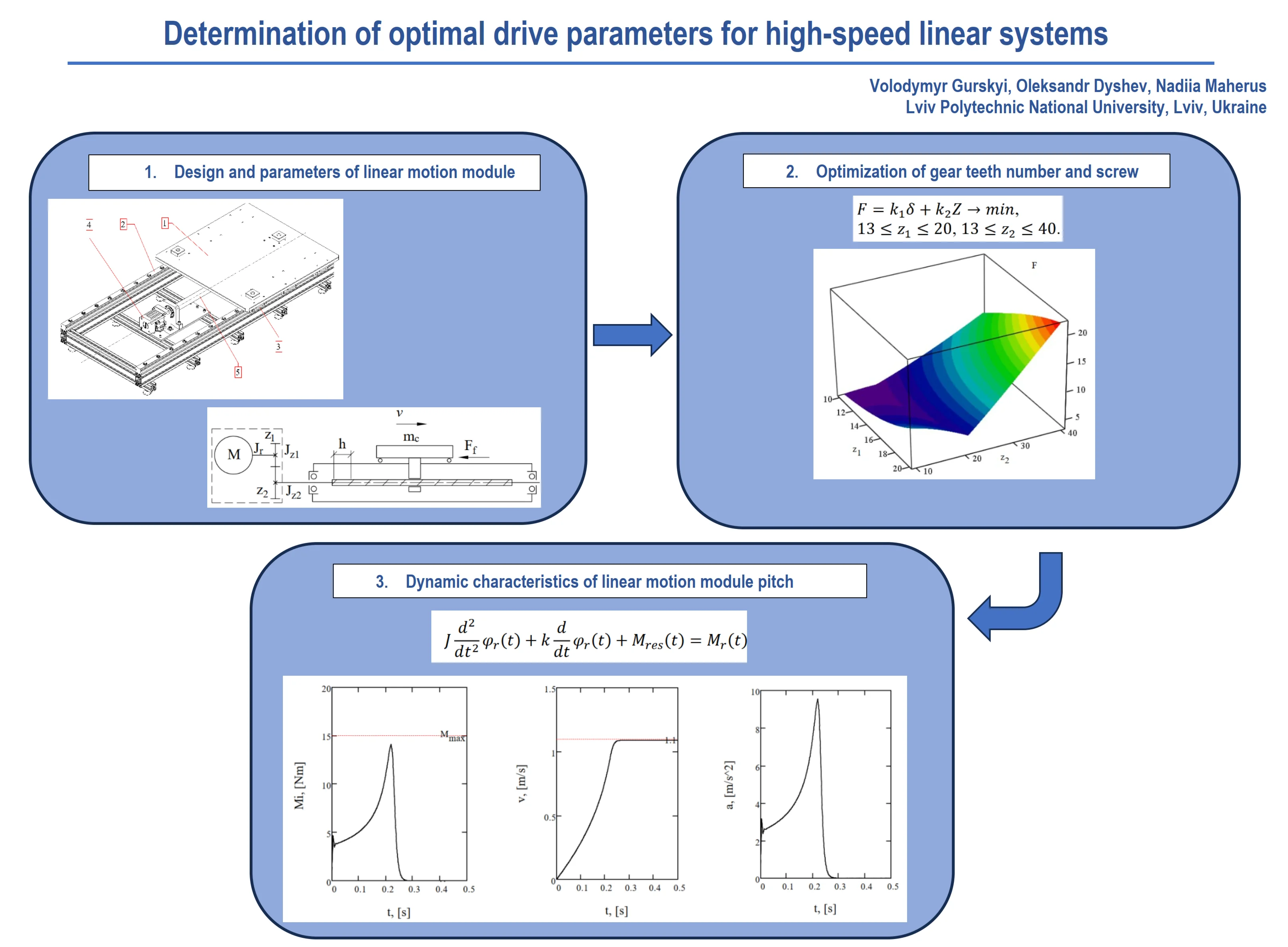
- Design and parameters of linear motion module.
- Optimization of gear teeth number and screw.
- Dynamic characteristics of linear motion module pitch.
1. Introduction
The efficiency of robotic and machine-tool systems can be enhanced through the implementation of mechatronic systems for linear and rotary motion. These systems are used to expand the mobility capabilities of industrial robots, as well as to transport workpieces, components, and tools between technological equipment and industrial manipulators. They can also function as fully autonomous technological modules. Servo motors, asynchronous drives with gear reducers, motion conversion mechanisms based on belt or rack drives, and modular components using ball screw pairs are commonly used as actuators in these systems [1-3]. Such systems are capable of operating in high-speed reversing modes with linear travel speeds up to 1.89 m/s and a total load capacity up to 5000 kg [4]. Consequently, the primary source of power loss is due to inertial forces. Minimizing these forces is possible by applying energy-efficient principles at the design stage, when information about the drive is limited and a purely mechanical model of the system is used [5]. Naturally, this does not guarantee optimal energy performance [6].
The most commonly used approach in engineering estimations is to match the system’s kinematic and inertial characteristics with the energy characteristics of the drive and its operating conditions. Analysis of energy consumption is more accurate and is primarily applied to servo drives [7]. More refined analytical studies recommend the use of multiple criteria for evaluating energy efficiency and determining optimal operating conditions by using the laws of mechanical system motion [8-10].
The purpose of this research is to analytically determine the optimal gear ratio and ball screw pitch for linear mechatronic drive systems, and to refine these parameters through motion dynamics analysis.
2. Design and parameters of linear motion module
The main components of the linear motion module (see Fig. 1(a)) include the technological carriage 1 with a mass , which is mounted on the frame using linear rolling guideways 2, 3. The carriage is driven in translational motion at a velocity by a gear motor based on either an asynchronous or servo motor 4. The conversion to linear motion is carried out via a modular ball screw mechanism 5. The drive scheme presented in Fig. 1(b) includes the key kinematic and structural components that are determined during the design process. The gearbox section incorporates a high-precision gear transmission or a toothed belt transmission with the numbers of teeth of the driving and driven gears denoted as and , respectively.
Fig. 1a) Design and b) drive scheme of the linear motion module: 1 – carriage; 2, 3 – linear rolling guideways; 4 – servo motor with gearbox; 5 – modular ball screw mechanism
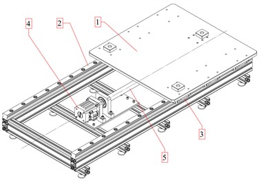
a)
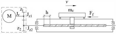
b)
The inertial torque of moving masses acting on the motor shaft is determined by the following dependence:
where is the equivalent moment of inertia of the moving masses referred to the motor shaft; is the gear ratio of the intermediate (gear or toothed belt) transmission; , are the angular accelerations:
where , , are the moments of inertia of the motor rotor and the gear wheels, respectively; is the mass of the carriage including the payload; is the carriage velocity; is the angular velocity of the motor rotor.
In the case of using a rotary-to-linear motion conversion mechanism based on a ball screw transmission, the carriage linear velocity is expressed as follows:
where is the screw pitch; is the number of starts (typically, ).
If the limitation on the maximum allowable acceleration of the carriage is known, the angular acceleration of the screw used in Eq. (1) is determined by the following dependence:
From the condition , an equation was derived to estimate the optimal gear ratio , which ensures the minimum value of the inertial torque :
In Eq. (5), it is also possible to take into account the moments of inertia of the screw and the coupling, referred to the respective shaft to which the coupling is mounted. If the moments of inertia of the gear wheels and are neglected, Eq. (5) takes the simplified form:
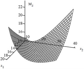
Using Eq. (1) together with Eq. (2-4), it is obtained the functional dependence , the graph of which is presented in Fig. 2 for the following numerical values of the mechanical system parameters: 0.0025 kg∙m2, , 314 s-1, 10 m/s2 , 200 kg, 32∙10-3 m. The dimensions of the ball screws are selected according to DIN 69051 and ISO 3408 standards.
The graph shows the presence of a minimum of the inertial torque 14.1 Nm, which indicates the possibility of selecting the optimal gear ratio 1.44 for the drive of the linear systems, as defined by Eq. (6). The carriage velocity, according to Eq. (3), is 1.1 m/s.
Fig. 2a) Dependence of the inertial torque on the gear ratio and b) the number of teeth
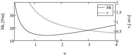
a)
b)
3. Optimization of gear teeth number and screw pitch
According to Eq. (5), the screw pitch and the number of teeth and are considered optimization parameters. In this case, the screw pitch is determined from Eq. (3) as a functional dependence to ensure the specified carriage velocity .
Moments of inertia of the gear wheels:
The possible calculated values of the gear ratio may differ from the optimal value (5) with the following relative error:
To achieve a more compact drive system, an additional function is incorporated, namely the total number of teeth of the driving and driven gear wheels:
These two objective functions are reduced to a single generalized function under the following constraints:
where , are weighting coefficients that transform Eq. (10) into an extremal form and enable the solution of the optimization problem. This approach makes it possible to ensure the existence of a single minimum of the objective function Eq. (10) (see Fig. 3). The values of the weighting coefficients that allow obtaining this minimum are selected as , .
Table 1Parameters of the linear motion module
Parameter | Designation | Units | Value |
Moment of inertia of the motor rotor | kg∙m2 | 0.0025 | |
Gear module | m | 0.003 | |
Face width | m | 0.040 | |
Density of the gear material | kg/m3 | 7700 | |
Carriage mass | kg | 200 | |
Carriage velocity | m/s | 1.1 | |
Angular velocity of the drive shaft | s-1 | 314 |
Fig. 3Dependence of the objective function on the number of teeth of the driving and driven gears
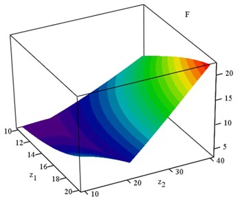
The obtained parameter values are , , , 0.2 %, . According to Eq. (3), the calculated screw pitch is 27 mm. Increased pitch values of the helical line are provided by special spiral screws. If a standardized [11] screw pitch value of 32 mm is used, the optimal number of teeth will be 13 and 19, and the gear ratio will be 1.46.
4. Dynamic characteristics of linear motion module
The linear motion module is defined by a single generalized coordinate, namely the angular position of the drive shaft . By applying the principle of referring the resistance forces and inertial torques to the drive shaft, the law of its motion is determined as follows:
where is the viscous resistance coefficient, 0.001 N∙m∙s/rad; is the resisting torque caused by the friction forces in the linear rolling guideways; is the friction force; is the equivalent coefficient of friction, is the time-dependent driving torque based on the asynchronous motor model; is the maximal torque value, 15 Nm; is the slip value at the point of maximal torque, ; is the rotational speed of the flux of the motor, 314 s-1.
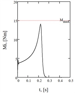
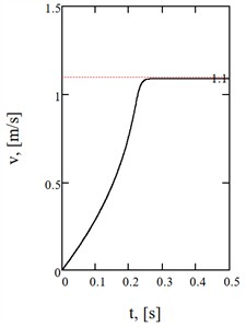
To evaluate the dynamic behavior of the linear motion module, the main time-dependent characteristics are presented for the equivalent inertial torque, carriage velocity and acceleration (see Fig. 4, Table 2). The maximum value of the inertial torque is 14.1 Nm, the carriage velocity is 1.08 m/s and the acceleration is 9.54 m/s2. The root mean square power within the time interval 0,…, 1 s is 840 W.
Table 2Kinematic characteristics of the linear motion module
Number of teeth, | Gear ratio, | Screw pitch, , mm | Carriage velocity, , m/s | Power, , W |
13/16 | 1.23 | 27 | 1.09 | 838 |
13/19 | 1.46 | 32* | 1.08 | 840 |
13/24 | 1.85 | 40* | 1.08 | 842 |
* standard values | ||||
Fig. 4Time-dependent curves of a) the equivalent inertial torque, b) carriage velocity, and c) carriage acceleration
a)
b)
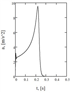
c)
In the considered case, the inertia of the rotating masses has no significant effect, so Eq. (6) is suitable for determining the optimal drive parameters.
5. Conclusions
Approaches for determining the gear ratio , the number of teeth , and the screw pitch of the ball screw drive in linear motion modules are developed. The estimation is based on the method of referring the moving masses to the motor shaft and minimizing the relative error between the actual and optimal gear ratio, taking into account the total number of teeth and the inertia of the rotating masses. The obtained numbers of teeth are refined in the second stage of the calculation and adjusted to match standardized screw pitch sizes. The resulting calculated parameters were validated through the dynamic analysis of the drive system with the asynchronous electric motor.
References
-
W. Sun, X. Kong, and B. Wang, “Precise finite element modeling and analysis of dynamics of linear rolling guideway on supporting direction,” Journal of Vibroengineering, Vol. 15, No. 3, p. 2013, Sep. 2013.
-
C. Zhu, L. Zhu, and J. Shi, “Research on dynamic performance of feed drive systems by integrating the virtual prototype and finite element method,” Journal of Vibroengineering, Vol. 17, No. 4, Jun. 2015.
-
Y. Zhang, C. Zhou, and H. Feng, “A novel calculation expression for the experimental friction coefficient of the ball screw,” Vibroengineering Procedia, Vol. 38, pp. 80–84, Jun. 2021, https://doi.org/10.21595/vp.2021.22037
-
“Robot linear units,” KUKA, https://www.kuka.com/en-de/products/robot-systems/robot-periphery/linear-units (accessed Jun. 2025).
-
P. Boscariol and D. Richiedei, “Revisiting the inertia matching condition for energy efficiency,” Mechanics Based Design of Structures and Machines, Vol. 52, No. 10, pp. 7430–7444, Jan. 2024, https://doi.org/10.1080/15397734.2023.2299312
-
P. Boscariol, R. Caracciolo, and D. Richiedei, “Does inertia matching imply energy efficiency?,” in Mechanisms and Machine Science, pp. 282–289, Oct. 2021, https://doi.org/10.1007/978-3-030-87383-7_31
-
P. Boscariol and D. Richiedei, “Energy optimal design of servo-actuated systems: A concurrent approach based on scaling rules,” Renewable and Sustainable Energy Reviews, Vol. 156, p. 111923, Mar. 2022, https://doi.org/10.1016/j.rser.2021.111923
-
V. S. Loveikin, Y. O. Romasevich, A. V. Loveikin, A. S. Khoroshun, and M. M. Korobko, “Minimizing the driving torque of tower crane slewing mechanism during steady trolleying,” International Applied Mechanics, Vol. 59, No. 6, pp. 695–707, Mar. 2024, https://doi.org/10.1007/s10778-024-01252-2
-
V. S. Loveikin, Y. O. Romasevych, A. V. Loveikin, A. S. Khoroshun, and A. P. Liashko, “Power criterion optimization of concurrent start of trolleying and slewing mechanisms in tower crane,” International Applied Mechanics, Vol. 60, No. 4, pp. 431–445, Dec. 2024, https://doi.org/10.1007/s10778-024-01295-5
-
V. Loveikin, Y. Romasevych, A. Loveikin, and M. Korobko, “Optimization of the trolley mechanism acceleration during tower crane steady slewing,” Archive of Mechanical Engineering, pp. 411–429, Jan. 2022, https://doi.org/10.24425/ame.2022.140424
-
“Ball Screws,” Thomson Industries, https://www.thomsonlinear.com/en/products/ball-screws.
About this article

The authors have not disclosed any funding.
The datasets generated during and/or analyzed during the current study are available from the corresponding author on reasonable request.
