Abstract
A mathematical model of dynamic processes in asynchronous motors that takes into account interrconnection between electromagnetic phenomena in electric machine and mechanical oscillation is considered. For motors of the most common designs, it is assumed that the axis of rotation of the rotor relatively to the stator is immovable; the stator is based on flexible supports. The results of calculations of vibration processes in asynchronous motors are presented. In particular, the influence of stiffness-dissipative parameters of stator supports on the maximum values of forces in stator supports and the angular displacements of the stator are analyzed.
Highlights
- A mathematical model of dynamic processes in asynchronous motors that takes into account interrconnection between electromagnetic phenomena in electric machine and mechanical oscillation is developed.
- The results of calculations of vibration processes in asynchronous motors are presented.
- The maximum values of forces in stator supports and the angular displacements of the stator are analyzed.
1. Introduction
The problems of mathematical modeling of vibrations of asynchronous motors with both constant and variable air gaps are given considerable attention in the literature. As noted in [1], vibration phenomena in motors can lead to breakdowns and abnormal noise in electrical machines. Results of studies of coupled vibrations of the engine, gearbox, bogie frames of the traction unit, conducted using multidimensional finite element models, are presented in [2]; the vibration levels of the transport machine elements were investigated taking into account the operation of the drive control system in the entire range of operating speeds. In order to reduce the impact of dynamic loads on the operation of drive systems, impedance control is used. In article [3], this problem is solved using a torque controller or speed controller.
The results of research of noise and vibration of asynchronous motors have found wide application in technical diagnostics, for example, for detection of malfunctioning of rolling bearings [4]. Nowadays, there is a growing demand for efficient electric motors in various industries, particularly in the electric vehicle manufacturing industry [5], noise and vibration control is essential in the design of automotive electric motors; the analysis of forced vibrations of asynchronous motors under operating conditions is presented in this article.
The mathematical model of dynamic processes in asynchronous motors, based on the account of the interrelation of electromagnetic phenomena in an electric machine and mechanical vibration phenomena, is considered in this report. Considering the most common engine designs, it is assumed that the stator has flexible supports relative to its base and the rotor has absolutely rigid supports relative to the stator.
2. Equation of motion of the mechanical system of an asynchronous electric motor
Depending on the parameters of elements of the machine unit system and the operating mode, the motor can either exhibit damping properties or excite mechanical vibrations. During the start-up of electric motors, significant oscillations in driving torque occur due to electromagnetic transient processes, which leads to significant vibrations and dynamic loads on transmission mechanisms and supporting structures. On the other hand, the motor’s response to a sudden increase of resistance torque after the drive has been accelerated contributes to suppression of vibrations in the mechanical system.
Let us focus on the analysis of vibrations in asynchronous motors, which are widely used in industry.
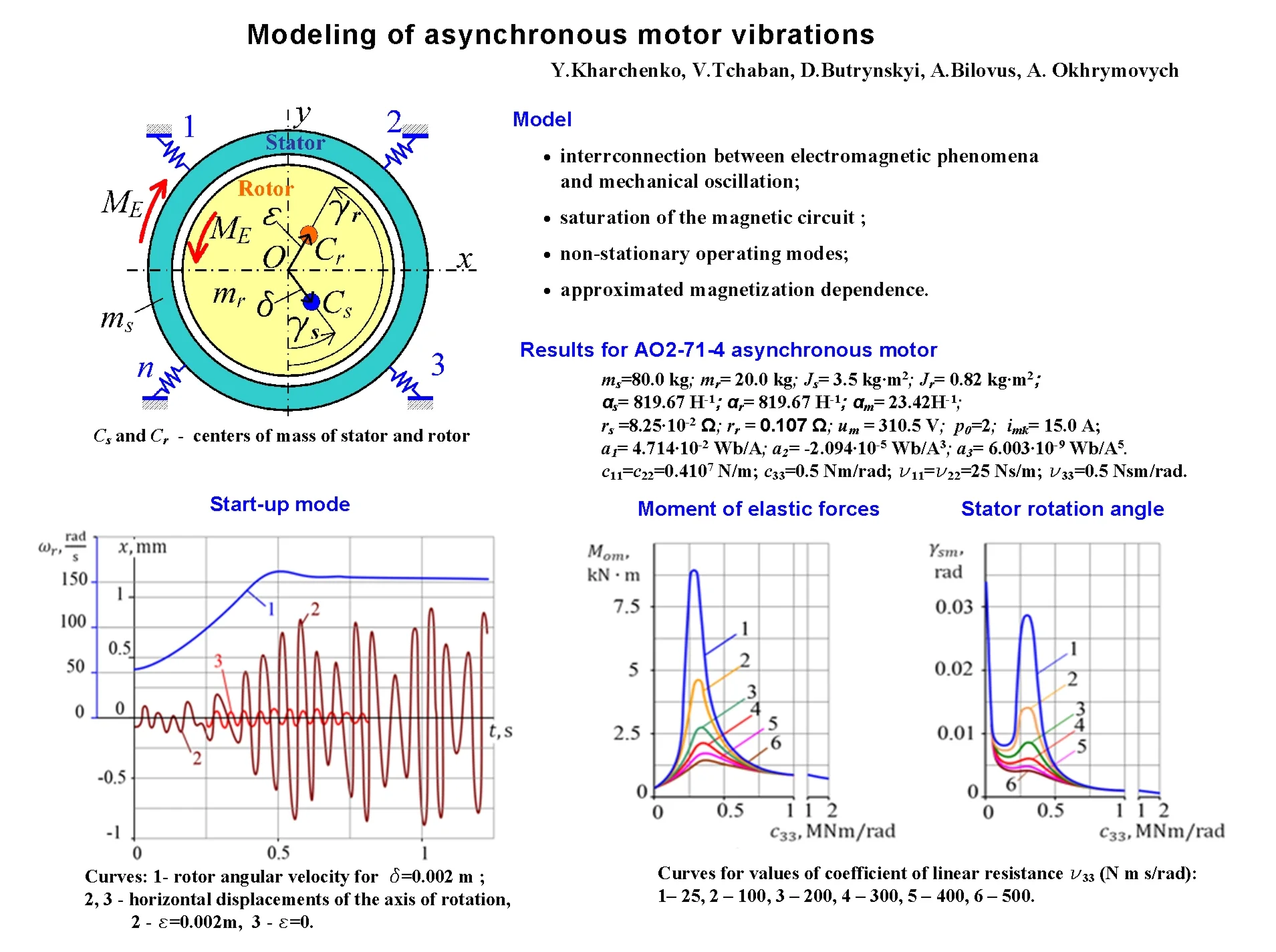
We consider the stator and rotor of the motor (Fig. 1) as absolutely rigid bodies with masses and moments of inertia and relative to the centers of mass and respectively. The indices and indicate that the parameters belong to the stator and rotor windings. The stator is installed on elastic supports 1, 2, ..., . The flexibility of the shaft and its supports is neglected. The imbalance of the stator and rotor structures is taken into account by the location of their centers of mass and relative to the rotation axis of the rotor with eccentricities and respectively.
Fig. 1The calculation scheme of the asynchronous motor
We compose the equations of motion for the stator and rotor according to the scheme of the second-order Lagrange equation:
where , , – the kinetic and potential energies of the system and the dissipative function of Rayleigh; – generalized coordinate; – generalized external force; – number of degrees of freedom.
Considering the motion of elements of a mechanical system in coordinates , , , (Fig. 1) kinetic energy is presented in the form:
Coefficients of static stiffness of supports in coordinate directions , , are denoted as , , and mixed stiffnesses as , , where 1, 2, …, . Similarly, the resistance coefficients characterizing the dissipative properties of the supports are denoted by , , , , , . It is assumed that resistance coefficients as well as static stiffness coefficients satisfy the symmetry condition.
The potential energy of the system is expressed as:
where , – translation along the and axes of the joint point of the -th support to the stator.
In the absence of stator displacement, the coordinates of the specified point are and then their value and , by taking into account small displacement of the specified engine element, are determined by the following expressions:
The dissipative function is represented as:
Using the Eq. (2) for kinetic and Eq. (3) for potential energies and the Rayleigh function Eq. (5), taking into account the dependencies Eq. (4), we transform Eq. (1) to the form:
where , , – square matrices:
where coefficients of matrix , , are inertia coefficients, viscous friction coefficients and stiffness coefficients of the mechanical system; , , – column matrices:
where , – speed of the axis movements O in the directions of coordinates and ; , – angular velocities of the stator and rotor; – electromagnetic torque of the motor; – moment of resistance forces.
3. Equations of the electromagnetic state of an asynchronous motor
Taking into account the practical application of refined analysis of the vibration activity of drive motors during non-stationary operating modes of machines, we will apply a mathematical model of electric machine that allows us to take into account the saturation of the magnetic circuit. The differential equations of the electromagnetic state of an asynchronous motor are [6]:
where , , – matrices-columns of electric currents and voltages; , , , – interrelation matrices; , – rotation frequency matrices; , – column matrices of flow coupling; , – active resistances.
Column matrices , , are determined by the following equations:
where , – projections of currents onto the coordinate axes , ; – the amplitude of the supply voltage.
The matrices , , , are calculated by the following:
where: , , – the magnetisation current and its components along the axes , ; , – are values inverse to the inductance dispersion of the stator and rotor windings; the and are determined by the following relations:
where – the working flux linkage.
Magnetization dependences are usually provided by the manufacturer as measured discrete data (in tables) or curves, their further approximation and extrapolation are applied [7]; in our case, the magnetization dependence is approximated as:
where is the inverse of the working inductance of the motor; is the critical value of the magnetizing current, beyond which the dependence is nonlinear.
The rotational frequency matrices are written as:
here – synchronous rotation speed; – speed of rotor rotation relative to stator, .
The column matrices of the total stator and rotor flux linkage are determined by the following relations:
The electromagnetic moment is determined by the formula:
Substituting the expression of the electromagnetic moment of the induction motor Eq. (12) into Eq. (6), as well as the expressions of the parameters and , obtained from relations Eqs. (10) and (9), into Eq. (7), we form the Cauchy problem from the differential Eqs. (6), (7). The initial values of the displacements and projections of the currents onto the coordinate axes are taken equal to zero. Due to the nonlinearity of this problem, it will be solved numerically.
4. Results of research
Let us consider dynamic phenomena in the AO2-71-4 asynchronous motor, which is equipped with the UKB-4P drilling rig. The parameters of the electromechanical system of the motor are taken as follows: 80.0 kg; 20.0 kg; 3.5 kg∙m2; 0.82 kg∙m2; 819.67 H-1; 819.67 H-1; 23.42H-1; 8.25×10⁻² Ω; 0.107 Ω; 310.5 V; 2; 4.714×10⁻² Wb/A; –2.094×10⁻⁵ Wb/A3; 6.003×10⁻⁹ Wb/A5; 15.0 A.
The numerical solution of the problem was obtained using the 4th order Runge-Kutta method with a fixed time integration step equal to 2×10⁻⁵ s, the relative cumulative error of the solution estimated using the multiple solutions technique does not exceed 0.01.
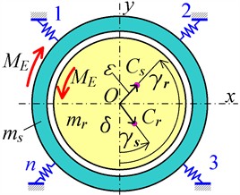
Results of vibrations calculation of the asynchronous motor in the cross-sectional plane are shown in Fig. 2. The non-zero elements of matrices and are assumed to be equal to the: 0.4×10⁷ N/m; c33=0.5 N∙m/rad; 25 N∙s/m; 0.5 N∙s∙m/rad. Curves 1…3 correspond to the following values of the eccentricities 0.02 m, 0.002 m, 0 m.
Fig. 2Dependencies of the rotor angular velocity (curve 1) and horizontal displacement of the axis of rotation (curves 2, 3) during engine start-up
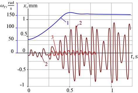
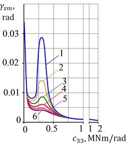
Fig. 3 shows graphs of the maximum moment of the support forces and the maximum angle of the stator rotation, built based on calculations of engine start-up processes.
Curves 1…6 correspond to the following values of the coefficient of linear resistance : 25, 100, 200, 300, 400, 500 N·m·s/rad. As can be seen from the obtained results, the specified parameters during engine start-up in a mode close to resonance significantly depend on energy dissipation in the supports. For real values of the linear resistance coefficient, the maximum torque significantly exceeds the maximum electromagnetic torque, therefore resonance phenomena are highly undesirable.
5. Conclusions
Conducted research shows that drive motors, which are widely used in technological machines, can exhibit significant vibration activity. Dynamic phenomena must be taken into account during the design and operation of drive systems of machine units.
In order to eliminate transverse vibrations of engine elements, it is necessary to balance the rotor and stator with high accuracy, align the center of mass of the stator with the axis of rotation of the rotor, and also eliminate the mutual influence of translational and rotational movements of the stator. It should be noted that a significant reduction in vibration levels can be achieved by balancing only the rotor.
Fig. 3Graphs of maximum values of a) the moment of elastic forces and b) stator rotation angle
a)
b)
Self-oscillations that occur in the electromechanical system of an asynchronous motor due to the convergence of the voltage oscillations frequency and one of the mechanical oscillations eigen frequencies are extremely undesirable. This phenomenon can be interpreted as the occurrence of electromechanical resonance, which leads to a significant increase in both the amplitudes of the system elements oscillations and the dynamic loads on the bearings and supporting units of the machine. Resonance can be avoided by reducing the stiffness of the stator supports. In this case, the dynamic loads on the foundation are reduced, but the amplitudes of stator oscillations can increase significantly.
Increasing the stator’s eigen frequency by improving the stiffness of the supports makes it possible to reduce the motor’s vibration activity. As a result of the increasing the maximum value of the elastic force moment gradually decreases, asymptotically approaching the maximum value of the torque, and the amplitude of the stator oscillations decreases, approaching zero.
References
-
Z. Wang, J. Zhang, and Y. Liang, “Motor noise and vibration test research,” Telkomnika (Telecommunication Computing Electronics and Control), Vol. 11, No. 1, p. 87, Mar. 2013, https://doi.org/10.12928/telkomnika.v11i1.886
-
G. Kobenkins, M. Marinbahs, A. Bizans, N. Rilevs, and O. Sliskis, “The influence of dynamic loads on the vibration level of rotating units of traction drives,” Energy Reports, Vol. 9, pp. 131–137, May 2023, https://doi.org/10.1016/j.egyr.2022.12.114
-
M. Mosadeghzad, G. A. Medrano-Cerda, J. A. Saglia, N. G. Tsagarakis, and D. G. Caldwell, “Impedance control of a class of series elastic actuators: performance limitations arising from link dynamics, disturbance attenuation and impedance emulation,” Department of Advanced Robotics, Istituto Italiano di Tecnologia, Genoa, Italy, 2014.
-
Z. Wang, D. Shi, Y. Xu, D. Zhen, F. Gu, and A. D. Ball, “Early rolling bearing fault diagnosis in induction motors based on on-rotor sensing vibrations,” Measurement, Vol. 222, p. 113614, Nov. 2023, https://doi.org/10.1016/j.measurement.2023.113614
-
A. Saito and T. Suzuki, “Forced response vibration analysis of induction motor stators induced by electromagnetic forces,” IFAC-PapersOnLine, Vol. 55, No. 27, pp. 155–159, Jan. 2022, https://doi.org/10.1016/j.ifacol.2022.10.504
-
A. Chaban, Hamiltion-Ostrogradsky Principle in Electromechanical Systems. (in Ukrainian), Lviv, Ukraine: Soroki, 2015.
-
M. Hadžiselimović, T. Marčič, and I. Zagradišnik, “Efficient approximation procedure for magnetization characteristics used in performance analysis of highly saturated electrical machines,” Energies, Vol. 17, No. 23, p. 6073, Dec. 2024, https://doi.org/10.3390/en17236073
About this article

The authors have not disclosed any funding.
The datasets generated during and/or analyzed during the current study are available from the corresponding author on reasonable request.
The authors declare that they have no conflict of interest.
