Abstract
This study investigates the structural optimization, lightweight design, and fatigue life influencing factors of the excavator working device through comprehensive static and dynamic finite element analysis (FEA). Modal analysis, spectral analysis, and vibration transfer path identification were conducted to assess the vibration response and fatigue failure risks at key joints such as the forearm pinholes. The inclusion of figures, such as vibration paths and stress distribution plots (see Figs. 3-8), supports the findings. The research provides a theoretical basis for assessing the structural reliability and fatigue life of long-arm excavators exceeding 25 meters.
Highlights
- Structural optimization and lightweight design: Simulation analysis can identify stress concentration areas in the structure, thereby optimizing the design, reducing weight and improving strength.
- Failure prediction: By analyzing mechanical behaviors such as fatigue, creep and fracture, the life and failure mode of the mechanical structure are predicted.
- Dynamic response analysis: Simulate dynamic loads such as impact and vibration to evaluate the dynamic characteristics of the structure and improve reliability.
1. Introduction
Mechanical structure mechanics simulation is an important technology that uses computer-aided tools to predict and analyze the mechanical properties of mechanical structures under specific working conditions [1]. It is widely used in mechanical design, structural optimization and fault diagnosis. Through numerical simulation, it can effectively reduce experimental costs and improve design efficiency and product reliability [2].
As an important equipment of construction machinery, the structural simulation analysis of excavators is of great significance for optimizing design, improving performance and extending service life. At present, the research mainly focuses on the following aspects:
Multibody dynamics simulation (MBD) technology is widely used in the working devices of excavators, such as booms, dipper arms and buckets, to study their motion characteristics and stress conditions. Through dynamic simulation, the working cycle of the excavator can be optimized, the working efficiency improved, and the structural fatigue damage reduced (see Fig. 1 for structural schematic). Through dynamic simulation, the working cycle of the excavator can be optimized, the working efficiency can be improved and the structural fatigue damage can be reduced [3]. The hydraulic system is the core drive unit of the excavator, and its performance directly affects the efficiency of the whole machine. Researchers use software such as AMESim and MATLAB/Simulink to simulate the hydraulic system to optimize the parameters of hydraulic components, reduce energy consumption and improve control accuracy [4]. Finite element analysis (FEA) is used to evaluate the strength and stiffness of key components of excavators (such as booms, chassis and slewing mechanisms). Studies have shown that the use of topology optimization methods can reduce material usage and manufacturing costs while ensuring structural strength [5].Virtual prototype (VP) technology combines multi-body dynamics, hydraulic system simulation and finite element analysis to enable engineers to optimize excavator design in a digital environment and reduce the manufacturing cost and testing time of physical prototypes [6].In order to improve operator comfort and safety, researchers use simulation technology to evaluate cab layout, vibration response and control interface design, thereby optimizing the excavator operating experience [7].
This paper further explores the propagation law of vibration in the excavator structure and its impact on fatigue life. Vibration not only directly affects the local stress distribution of the structure, but is also likely to cause resonance, fatigue accumulation and early failure. (See Fig. 1 for schematic diagram.) Therefore, this study conducted a detailed analysis of the vibration response at different impact frequencies (150-300 bpm), and combined modal tests with numerical simulations to reveal the transmission path and distribution characteristics of vibration energy in key parts (such as the forearm).
2. Equipment structure and model building
2.1. Main working device
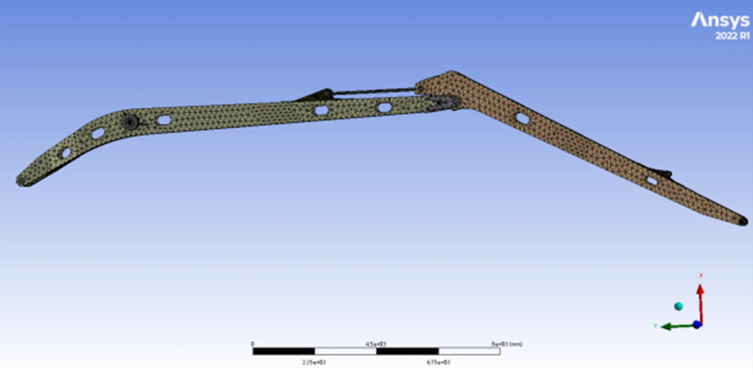
Fig. 1 shows the general schematic of the working device.
Fig. 1General assembly drawing
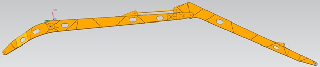
Table 1Name and material properties of each structure
Name | Material | Density (kg/m3) | Young’s modulus (MPa) | Poisson’s ratio | Tensile strength (MPa) |
Boom seat ear seat | Q345 | 7850 | 200000 | 0.3 | 345 |
Rear stand | Q420 | 7850 | 206000 | 0.25 | 420 |
Neutral board | Q420 | 7850 | 206000 | 0.25 | 420 |
Front stand | Q420 | 7850 | 206000 | 0.25 | 420 |
Boom upper cover | Q420 | 7850 | 206000 | 0.25 | 420 |
Boom lower cover | Q420 | 7850 | 206000 | 0.25 | 420 |
Arm cylinder tail ear seat | Q345 | 7850 | 200000 | 0.3 | 345 |
Ear stop block | Q345 | 7850 | 200000 | 0.3 | 345 |
Ear seat stop plate | Q345 | 7850 | 200000 | 0.3 | 345 |
The tail ear of the large pump cylinder should be a stopper | Q345 | 7850 | 200000 | 0.3 | 345 |
Boom fork | Q345 | 7850 | 200000 | 0.3 | 345 |
Boom seat ear seat sealing plate | Q345 | 7850 | 200000 | 0.3 | 345 |
2.2. Element type selection and meshing
According to the shape of the unit, it can be divided into solid unit, shell unit and beam unit; secondly, solid unit can be divided into hexahedral unit and tetrahedral unit, and shell unit can be divided into quadrilateral unit and triangular unit; according to the complexity of the unit shape function, it can be divided into first-order unit and second-order unit. The main structural parts of the finite element model established in this paper are simulated by solid186 unit.
This paper adopts solid unit modeling, and the quality of the mesh has a great influence on the accuracy of the calculation. If the unit quality is too poor, the calculation may be terminated. Tetrahedral mesh can be generated quickly and automatically, without much user intervention and with a high success rate of mesh division, which is suitable for complex geometric shapes. Hexahedral mesh division takes a lot of time and requires high mesh division experience, but the number of meshes is small, which can save calculation time and has high accuracy.
Therefore, we choose to use hexahedral meshes for simple stiffeners, stiffeners, and the main body of the big arm and small arm, and tetrahedral meshes for the remaining relatively complex parts that have little impact on the analysis results.
2.3. Mesh density determination and model correctness verification
The quality of mesh generation has a very important impact on both steady and unsteady calculations. An appropriate number of meshes in the flow channel can greatly improve the accuracy of the calculation, while a coarse mesh may lead to reduced accuracy or even erroneous calculation results due to the inability to calculate some small-scale flow phenomena, as shown in Fig. 2, which compares sparse and refined mesh regions.
Fig. 2Finite element model of the whole machine with different mesh densities
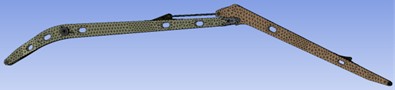
a) Sparse grid

b) Refine the grid
3. Finite element analysis of static stress-strain state
Fig. 1 presents the schematic diagram of the main working device. Table 1 lists the material properties of each structural component used in the simulation. To ensure accuracy, Fig. 2 shows comparisons between sparse and refined mesh regions.
Table 2Table of the maximum stress and maximum strain points of each component
Part | Maximum stress point | Simulation value (MPa) | part | Maximum stress point | Simulation value (MPa) |
Boom seat ear seat |  | 33.80 | Upper ear seat | 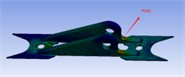 | 12.54 |
Boom body |  | 31.23 | Middle pump rod head ear seat |  | 15.38 |
Boom fork | 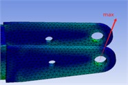 | 32.59 | Arm body | 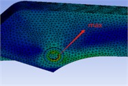 | 89.38 |
Conclusion: As shown in Table 2, the maximum stress occurs at the pin hole of the forearm with a value of 89.38 MPa, which is significantly below the material yield limit (420 MPa). This result is visually confirmed by the contour plots in Fig. 5. The equipment can operate normally, but to ensure long-term safety, the forearm pin hole needs to be reinforced. (see Fig. 5 for visualized stress distribution)
4. Finite element analysis of dynamic stress-strain state
4.1. Stress analysis
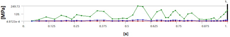
The weight of the breaker is 4232 kg, the impact force is 120000 N, and the impact frequency is 150-300 bpm. Therefore, the end of the forearm needs to bear the weight of the breaker, which is 4232×9.8 N, and the reaction force of the breaker impact. The working impact frequency is 150-300 bpm. Take the minimum and maximum impact frequencies for analysis. The boundary conditions of the two reaction forces are illustrated in Figs. 3 to 5, corresponding to the extended arm, upper ear seat, and forearm.
The boundary conditions of the reaction force at the impact frequency of 150 bpm as illustrated in Figs. 6 to 8, the stress over time is visualized for the respective parts.
Fig. 3Extended arm

Fig. 4Upper ear seat

Fig. 5Extended forearm
The stress of each component changes with time under the reaction force boundary condition at a striking frequency of 300 bpm is as follows.
Fig. 6Extended arm
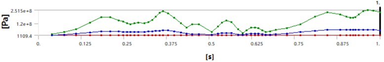
Fig. 7Upper ear seat

Fig. 8Extended forearm

4.2. Finite element dynamic analysis results
Modal analysis: Determine the sensitivity of each major component to vibration by extracting the natural frequency and vibration mode of the structure. Spectral analysis: Analyze the distribution of vibration energy in different frequency bands under the two working conditions of 150 bpm and 300 bpm, and identify the resonance risk area. Vibration transfer path study: Use signal processing methods to explore the transfer path of impact loads along the structure and clarify the vibration coupling effect between the forearm and other components. Under impact conditions of 150 bpm and 300 bpm (Figs. 3-8), the stress values in the arm body rise to 249.73 MPa and 385.48 MPa respectively. The vibration transfer path, as demonstrated in the modal analysis, indicates a strong coupling between the breaker and the forearm. Spectral peaks near 28 Hz suggest resonance risks, especially in extended configurations.
Table 3Finite element dynamic analysis results
Part | Maximum stress point | 150 bpm simulation value (MPa) | 300 bpm simulation value (MPa) |
Boom seat ear seat | 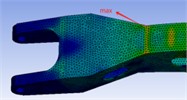 | 195.20 | 251.50 |
Boom body | 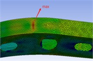 | 149.54 | 240.79 |
Boom fork | 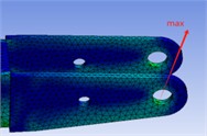 | 92.07 | 142.39 |
Upper ear seat | 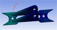 | 185.19 | 307.90 |
Middle pump rod head ear seat |  | 47.34 | 96.27 |
Arm body |  | 249.73 | 385.48 |
Through dynamic analysis, it is found that for a breaker with a clamp rod diameter of 175 mm, the maximum stress also occurs at the pin hole of the forearm, and the stress value is 385.48 MPa, which is less than the yield stress of the main material of 420 MPa, and can be used. To ensure safety during long-term use, the forearm pin hole needs to be reinforced.
When the horizontal arm of the structure exceeds 25 meters, due to the increased structural complexity and uneven dynamic response attenuation, this paper further proposes:
For the long arm design, add sensors for on-site monitoring, obtain vibration data in real time, and optimize the structure in combination with online simulation feedback.
Further study the relationship between impact frequency and vibration transmission path, establish a fatigue prediction model based on vibration signals, and provide data support for long-term safe operation.
5. Conclusions
This article determines the main parameters of the hydraulic excavator working device. The equipment structure is simulated using ANSYS software. After comprehensively considering various restrictive conditions, the finite element model of each component of the working device is established, and the overall finite element model is obtained by connection. Then, the static stress-strain state finite element analysis and the dynamic stress-strain state finite element analysis are carried out respectively. Although scholars have studied the structure of excavators in the past, there is still a lack of structural reliability analysis when the horizontal length of the mechanical arm exceeds 25 meters. The research in this paper provides important data reference for the reliability of long-arm excavators. The grid is divided into regions, and the grid is encrypted in areas of high stress concentration to improve calculation accuracy while reducing calculation costs. This article provides three references for equipment structure improvement.
1) Structural optimization and lightweight design: Simulation analysis can identify stress concentration areas in the structure, thereby optimizing the design, reducing weight and improving strength.
2) Failure prediction: By analyzing mechanical behaviors such as fatigue, creep and fracture, the life and failure mode of the mechanical structure are predicted.
3) Dynamic response analysis: Simulate dynamic loads such as impact and vibration to evaluate the dynamic characteristics of the structure and improve reliability.
After analyzing the location of the maximum stress of each device after the whole machine is equipped with a breaker, and the maximum stress value, the stability of the structure of the equipment when it is working and not working is determined.
In conclusion, this study not only verifies the safety of the excavator structure under static and dynamic loads, but also introduces a real-time vibration monitoring proposal for structures exceeding 25 meters in length. These insights are crucial for fatigue life assessment and design improvements. Figs. 1 through 8 support the structural behavior analysis presented.
Authors submitting a manuscript to Extrica Journals are required to declare any potential conflict of interests that could interfere with the objectivity or integrity of a publication. Conflict of interests may occur in situations that could be perceived to exert an undue influence on the presentation, review, or publication of a piece of work.
References
-
M. Zhang and H. Li, “Finite element analysis in mechanical structural design,” Journal of Mechanical Engineering, Vol. 65, No. 3, pp. 112–119, 2020.
-
Y. Wang and G. Li, “Structural simulation techniques in modern mechanical engineering,” International Journal of Mechanical Science, Vol. 48, No. 7, pp. 89–97, 2019.
-
D. Kim, S. Choi, and Y. Jeong, “Multi-body dynamic analysis of an excavator working device for load prediction and optimization,” International Journal of Heavy Vehicle Systems, Vol. 26, No. 3-4, pp. 245–260, 2019.
-
L. Zhang, X. Li, and T. Wang, “Simulation and optimization of excavator hydraulic system using AMESim and MATLAB/Simulink,” Autom. Constr., Vol. 125, p. 103570, 2021.
-
B. Lee and H. Park, “Finite element analysis and topology optimization of an excavator boom for lightweight design,” Engineering Structures, Vol. 210, p. 11032, 2020.
-
Y. Wang, “Application of virtual prototyping technology in excavator structural analysis and optimization,” International Journal of Computer Aided Engineering, Vol. 37, No. 2, pp. 90–103, 2020.
-
J. Chen, H. Liu, and P. Zhou, “Ergonomic simulation and optimization of excavator cabin design,” Journal of Mechanical Engineering, Vol. 45, No. 6, pp. 105–118, 2022.
About this article

The authors have not disclosed any funding.
The datasets generated during and/or analyzed during the current study are available from the corresponding author on reasonable request.
The authors declare that they have no conflict of interest.
