Abstract
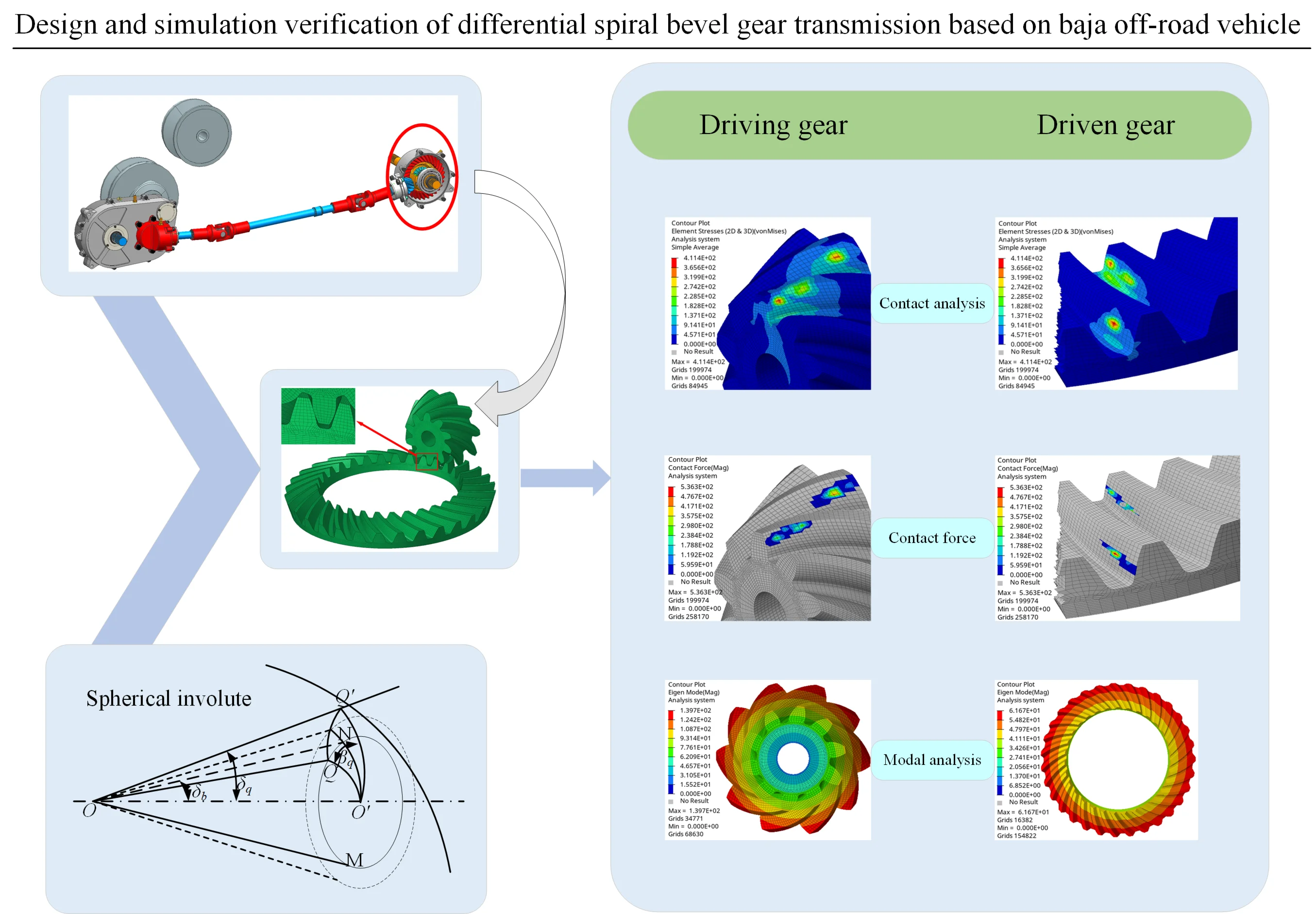
The differential spiral bevel gear of Baja off-road vehicle is designed and verified. Based on the competition rules and vehicle transmission parameters, the key geometric parameters of the gear pair are determined, and the three-dimensional model and finite element analysis software are established by UG for static contact analysis and modal analysis. The results show that the maximum contact stress of the tooth surface is 411.4 MPa, and the natural frequency of the gear pair is much higher than the excitation frequency of the system, which can effectively avoid the resonance risk. Through analysis and verification, it meets its application conditions.
Highlights
- Design spiral bevel gear parameters based on baja off-road vehicle working condition and differential structure size.
- Based on the theory of spherical involute and the principle of tooth wrapping, the three-dimensional model of spiral bevel gear is established by combining the tooth surface equation and motion constraint conditions.
- Evaluate the dynamic performance of spiral bevel gear under actual working conditions based on the first six modes to improve the reliability and stability of gear transmission system.
1. Introduction
Baja off-road vehicles are off-road racing cars designed for complex terrain, and in races they need to face road conditions such as sharp turns, puddles and steep slopes. Due to its frequent sharp turns and complex driving conditions, the differential gear must be designed to withstand heavy loads and impacts. Compared with traditional straight-tooth bevel gears, spiral bevel gears have significant advantages such as high transmission efficiency, good meshing performance and high load-bearing capacity, making them ideal for the differential of the Baja off-road vehicle.
At present, important results have been achieved in the research on spiral bevel gear transmission at home and abroad. Qi et al. [1] pointed out that the differential uses a spiral bevel gear transmission to obtain a high overlap coefficient, which improves its load-bearing capacity and transmission smoothness. Tang et al. [2] analyzed the impact of transmission errors on the dynamic characteristics of gears. Wang et al. [3] proposed a kinematic design method for face milling spiral bevel gears for high-order transmissions to improve gear transmission accuracy and reduce stress, thereby improving gear durability and reducing noise. Wang et al. [4] performed modal analysis on the reducer and revealed the “centrifugal stiffening effect” of the gear under high-speed rotation, which changes the modal characteristics of the gear. Mu et al. [5] proposed a high-order tooth surface modification method, which effectively reduces the vibration excitation of a spiral bevel gear transmission with a high contact ratio and improves the dynamic performance over the entire speed range. Shih et al. [6]-[7] proposed a gear modification method to improve the meshing performance of the gear. Most existing studies focus on the differential of commercial vehicles or passenger cars. There are few literatures on the strength and vibration characteristics of spiral bevel gear transmission of differentials under the working conditions of “short-time high impact and variable load” for Baja off-road vehicles. Especially, there are even fewer studies on the design and simulation verification of spiral bevel gear transmission of differentials for Baja off-road vehicles.
In this paper, according to the racing rules of Baja off-road vehicle, the spiral bevel gear of differential is calculated, a three-dimensional geometric model is established, and the reliability under complex working conditions such as short-term impact and frequent start-stop is analyzed by Hypermesh finite element software to ensure the differential can run stably under complex working conditions.
2. Spiral bevel gear design
2.1. Determination of relevant parameters
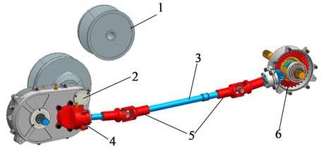
Compared with the conventional differential design, this paper mainly analyzes the complex working conditions such as short-term impact and frequent start-stop in Baja race, optimizes the gear parameters, and focuses on ensuring the instantaneous overload capacity under muddy and steep slopes. For this design objective, 20CrMnTi is selected as the material for the spiral bevel gear. Its elastic modulus is 207 GPa, Poisson’s ratio is 0.25, and the material density is 7800 kg/m3. After carburizing and quenching treatment, the surface hardness and core toughness of this material can be enhanced, thus meeting the load characteristics of the Baja off-road vehicle, which are “short-term impact and frequent start-stop”. According to AGMA 2101 standard, the allowable contact stress of the material after heat treatment is [] = 550 MPa. The engine of the Baja off-road vehicle is the Zongshen GB460V specified by the China Society of Automotive Engineers for the Baja competition, with a rated power of 12 kW. The competition rules require that the maximum engine speed must not exceed 3780 r/min. The power transmission from the Baja off-road vehicle to the differential is composed of a rubber belt CVT, a two-stage reduction gearbox, a universal joint and a drive shaft [8]. The composition and structure are shown in Fig. 1. Jin et al. [9] verified the speed regulation characteristics of rubber belt CVT used in Baja off-road vehicle through experiments. When the driving wheel speed is above 3000 r/min, it can maintain a high working efficiency, and its transmission efficiency is about 80 %. Pass the test, the speed ratio of rubber belt CVT can reach 0.5 when the soil is flat.
Fig. 1Transmission system of Baja off-road vehicle: 1 – rubber belt type CVT; 2 – two stage reduction gear; 3 – drive shaft length 760 mm (the display has been shortened to 250 mm); 4 – transfer case; 5 – gimbal; 6 – differential
The design speed of the racing car is 65 km/h, and the power of the transfer case comes from the intermediate shaft of the two-stage reducer and is input to the differential spiral bevel gear pair through the universal joint and transmission shaft. To ensure the same speed of the front and rear wheels when driving, the transmission ratio of its spiral bevel gear should be consistent with that of the low-speed stage of the second reducer. The transmission ratio of the two-stage reducer is 12.04, in which the transmission ratio of the low-speed stage is 3.09. Based on the selected parameters, materials, load-bearing capacity, and the complex driving conditions such as mud, steep slopes, and ditches that need to be faced [10], it combines the small size and high load-bearing requirements of the Baja off-road vehicle, and tries to minimize the radial size of the differential. Therefore, the number of teeth of the driving gear is chosen to be 10, and the number of teeth of the driven gear is 31. Based on the preliminary calculations of bending strength and contact strength, and considering the overall size of the differential, the gear module is selected as 4mm, and the tooth width is 20 mm. After calculation, the main parameters of the Grisson toothed bevel gear pair are shown in Table 1. Referring to the experimental results, the relevant input torque of the differential bevel gear pair's driving gear to be 52.03 N·m.
Table 1Main parameters of spiral bevel gear
Name | Driving gear | Driven gear |
Number of teeth () | 10 | 31 |
Module ( / mm) | 4 | 4 |
Tooth width ( / mm) | 20 | 20 |
Pressure angle ( / °) | 20 | 20 |
Midpoint helix angle ( / °) | 35 | 35 |
Direction of turning | Right | Left |
Reference diameter ( / mm) | 40 | 124 |
Reference cone angle ( / °) | 17.88 | 72.12 |
Outer cone distance ( / mm) | 65.15 | 65.15 |
Addendum (/ mm) | 4.8 | 2 |
Dedendum ( / mm) | 2.75 | 5.55 |
Tip angle (/ °) | 22.75 | 74.54 |
Root angle ( / °) | 15.46 | 67.52 |
2.2. Establishment of 3D model
The formation principle of spherical involute [11] is shown in Fig. 2. By simulating the pure rolling motion of the base circular cone and the plane, an accurate tooth profile surface is generated. This method serves as the theoretical basis for precisely constructing the three-dimensional model of involute conical gears. The cone Angle of the moving point and the deflection Angle after rotation are the basis for the construction of the size end curve of the tooth profile. The relationship between them can be expressed as:
Compared with Olcon’s system, Gleason's face milling method is chosen because it can produce higher meshing overlap under the configuration of small tooth difference and large helix angle ( 35°). The tooth system meets the core requirements of the differential of Baja off-road vehicle for high stability and high bearing capacity. Therefore, according to Gleason's idea of machining spiral bevel gears by face milling, the tooth surface geometry is enveloped by the relative motion between the disc milling cutter and the workpiece. A three-dimensional model of spiral bevel gear pair is established based on the crown wheel forming. The tooth surface of the bevel gear can be regarded as the crown wheel and tooth surface formed through the meshing envelope.
The tooth surface equation of the Gleason face milling method is based on the principle of envelope of a single-parameter surface family. It couples the geometric parameters of the cutter head with the motion of the machining center machine tool, and the diameter of the cutter head needs to satisfy , where is the radius of the crown gear and is the helix angle. Therefore, the cutter head coordinate system and the crown wheel coordinate system are defined, and the relative motion of the two is represented by the homogeneous transformation matrix :
where 35°, is the cone distance, and is the rotation Angle of the cutter disk.
The parametric equation of the cutter tooth profile in the cutter coordinate system is:
The tooth surface equation of the crown wheel is obtained according to the coordinate transformation, and the tooth profile surface equation of the bevel gear is obtained through the engagement envelope of the crown wheel and the tooth surface, and the three-dimensional model of the bevel gear is established by defining the motion constraints of the envelope condition. The tooth surface equation of the crown wheel is and the motion constraint condition is:
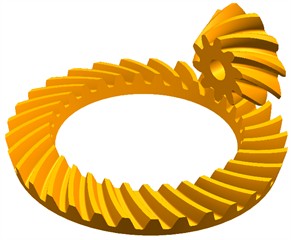
Based on Gleason’s tooth surface equation and coordinate transformation theory [12]-[13], MATLAB is used to solve the equation and obtain the data point set of gear geometric shape. The data points are imported into UG software, and the tooth profile curve and tooth surface sheet are generated by parametric modeling method. Finally, the three-dimensional modeling of spiral bevel gear is completed through entity operation. Assemble and check the solid model of spiral bevel gear obtained by modeling, as shown in Fig. 3.
Fig. 2Spherical involute principle
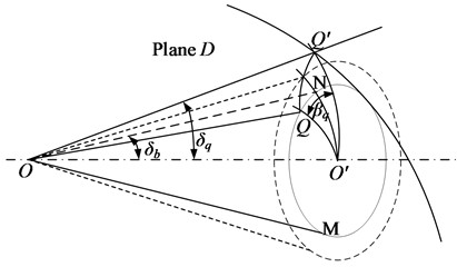
Fig. 3Solid model of spiral bevel gear
3. Static contact analysis of spiral bevel gear
3.1. Establishment of finite element mesh model
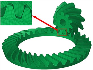
In CAE analysis, the size and quality of the mesh will have a great impact on the analysis, such as the solution speed and accuracy. Tetrahedral mesh [14] has high flexibility and can adapt to complex geometry, but its solution accuracy is not high, which may lead to instability of numerical solutions and poor shape quality. Aiming at the complex surface geometry of spiral bevel gear and the high stress gradient in the contact area of tooth surface, this paper chooses hexahedron-led grid division strategy. Compared with tetrahedral mesh, hexahedral mesh has higher calculation accuracy and numerical stability under the same mesh density, and can more accurately capture the distribution of tooth root bending stress and tooth surface contact stress. In this paper, the mesh division is a method of “dividing a single tooth into regular hexahedral mapping mesh, and then rotating and copying to generate a complete gear”, which ensures the high regularity and consistency of meshing tooth surface mesh, thus effectively improving the reliability of contact force and stress calculation and enhancing the convergence ability of nonlinear solution process. Aiming at the structure and working condition characteristics of the spiral bevel gear of Baja off-road vehicle differential, which has obvious complex surface characteristics and highly concentrated stress gradient, Hypermesh is used to divide the solid model of spiral bevel gear into hexahedral meshes. Solid edit is used to divide the solid model into simple and regular structures, 2D_automesh is used to mesh the single tooth surface, and then the general module of 3D_solid map is used to establish the single-tooth hexahedron mesh model. Finally, by using the rotate operation to replicate the rotation and the edges merge operation on the single-tooth hexahedral mesh model, the mesh model of the involute bevel gear can be obtained. As shown in Fig. 4. In finite element analysis, the quality of grid elements directly affects the accuracy and stability of solution. Jacobian ratio is a key index to evaluate the distortion degree of element shape. The closer it is to 1, the higher the calculation accuracy is. Referring to the general finite element analysis practice and related research, Jacobian ratio is usually required to be greater than 0.7 to ensure reliable calculation results in nonlinear contact problems and promote the convergence of solutions. In the grid created by this model, the proportion of cells with Jacobian > 0.7 reaches 95 %, which meets this recognized quality standard. And the remaining 5 % cells are in non-critical areas, which meets the simulation requirements and the calculation results are reliable.
Fig. 4Spiral bevel gear mesh model
3.2. Static contact stress analysis of spiral bevel gears
Tooth surface contact analysis of spiral bevel gear was carried out through finite element analysis software [15]-[17]. Create the contact surface of the master and slave gear teeth, define the contact pair contact type as S2S (face to face contact), set TRACK as FINITE (finite slip contact). Because Mobilube TM LS 85W-90 gear oil is used, the tooth surface has good lubrication conditions, so the friction coefficient between teeth is 0.06, in which the meshing tooth surface of gear teeth is the convex surface of driving gear and the concave surface of driven gear. The boundary conditions are defined as follows: the degrees of freedom of the inner ring of the driving gear are set as constraints except the degrees of freedom of the axial rotation, and the degrees of freedom of the cylindrical surface of the inner ring of the driven gear are all set as constraints. When the load is applied, the safety factor is taken to be 1.5, so the torque of 78.05 N·m is applied to the driving gear. The nonlinear analysis card NLPARM is created, and the PARAM card is loaded to improve the convergence of nonlinear analysis. The non-linear static module of Loadsteps analysis step is created, and OptiStruct is loaded to analyze the stress distribution of spiral bevel gear under this working condition. Element Stress [2D&3D] () and Contact Force () of Hyperview post-processing software were used to view the contact stress distribution cloud map and contact force of spiral bevel gear pair.
Fig. 5 shows the nephogram of contact stress distribution of spiral bevel gear pair. As can be seen from the figure, the maximum stress of the tooth surface at this meshing position is 411.4 MPa, which is less than the allowable contact stress of the material after heat treatment of 550 MPa, which is lower than the fatigue limit of the material, theoretically indicates that the gear has a good contact fatigue life, and the safety margin of contact strength is 1.34, which is enough to cover factors such as uncalculated dynamic load. The contact area is distributed in an elliptical step, and the maximum stress distribution area conforms to the actual meshing state of the gear. Edge contact occurred at the meshing position of the end face, which made the contact stress relatively high, and the highest stress was 168.2 MPa.
Fig. 5Stress cloud diagram of master and slave driving gear
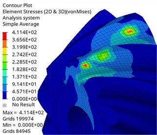
a) Driving gear contact stress cloud diagram
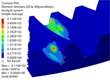
b) Contact stress cloud diagram of driven gear
As shown in Fig. 6, the maximum contact force of the master and slave driving gears appears on the tooth surface, with a value of 536.3 N. According to the distribution area of the force, the main contact position and contact trajectory distribution of the tooth surface can be obtained, which are consistent with the actual tooth meshing position. The maximum edge contact force obtained by loading the edge contact position is 16.13 N. For the case of edge contact, the contact mark can be improved by tiny tooth surface modification, which makes it more concentrated in the middle of the tooth surface, thus further improving reliability and service life.
Fig. 6Contact force of master and slave gears
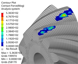
a) Driving gear contact force
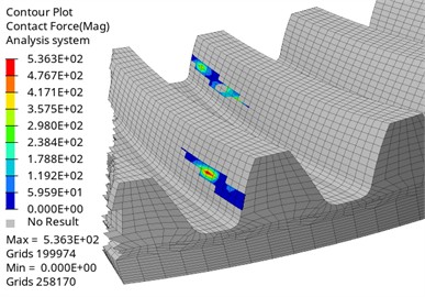
b) Driven gear contact force
4. Discussion
Modal analysis [18] is the process of describing a structure according to its inherent characteristics, which is used to study the dynamic characteristics of a structure or mechanical system [19], including natural frequency, modal shape and damping characteristics. This paper is based on the modal analysis of single gear. The vibration failure risk of gear transmission system is usually dominated by low-order modes, because the low-order modes correspond to the basic vibration characteristics of the overall stiffness and mass distribution of the structure, and the maximum input speed of the differential of Baja off-road vehicle is about 1950 r/min, and the load excitation under complex working conditions is mainly low frequency, and its modes have a significantly higher dynamic impact on gears than high-order frequencies, which is the core object that needs priority prevention and control, so the first six modes are selected for analysis. Modal analysis of spiral bevel gear is carried out, and the inner hole surface of the gear is selected as the constraint object as the boundary condition, and only the rotational freedom of the gear around the axis is released, and the other degrees of freedom are set as constraints.
By checking the results on the HyperView post-processing interface, the first six order natural frequencies and corresponding mode shapes of the driven and driven gears in modal analysis are shown in Table 2.
Table 2Modal parameters of the first six orders of the driving gear and driven gear
Driving gear | Driven gear | |||
Order | Inherent frequency / Hz | Vibration mode description | Inherent frequency / Hz | Vibration mode description |
1 | 0.0221 | Circumferential vibration | 0.02551 | Circumferential vibration |
2 | 39435.30 | Torsional vibration | 67240.84 | Torsional vibration |
3 | 39435.30 | Torsional vibration | 67240.85 | Torsional vibration |
4 | 41346.16 | Umbrella vibration | 67362.73 | Second-order folded vibration |
5 | 42596.57 | Twist vibration + umbrella vibration | 67362.75 | Second-order folded vibration |
6 | 42596.58 | Twist vibration + umbrella vibration | 67558.25 | Third-order folded vibration |
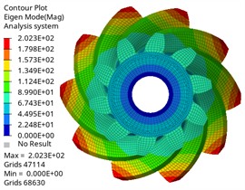
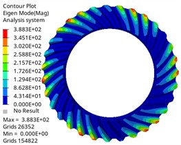
The vibration modes corresponding to the first six modes of the driving gear are shown in Fig. 7.
Fig. 7The first six modes of the driving gear
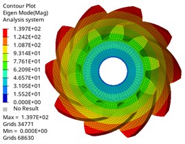
a) First-order mode shape
b) Second-order mode shape
c) Third-order mode shape
d) Fourth-order mode shape
e) Fifth-order mode shape
f) Sixth-order mode shape
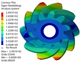
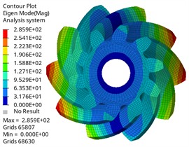
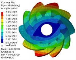
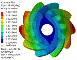
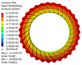
The vibration modes corresponding to the first six modes of the driven gear are shown in Fig. 8.
It can be found from the chart that the first-order natural frequency of the driving gear and the driven gear is almost 0 Hz, which corresponds to the rigid-body mode of the gear, and it will not be excited under actual constraints, which is a normal phenomenon, and the natural frequency change law is similar, which increases with the increase of modal order, and the natural frequency change is within 0.05Hz when the same vibration mode is different. In the same order, the natural frequency of the driving gear is lower than that of the driven gear. With different orders, the corresponding difference is also different, and the maximum difference is 27805.55 Hz, which is related to its large mass and structural characteristics. The maximum input speed of the differential of Baja off-road vehicle is about 1950 r/min, and the corresponding excitation frequency is 1950/60 = 32.5 Hz. The modal natural frequency obtained by analysis is much higher than this excitation frequency, which means that resonance will not occur in the normal driving range, which proves the reliability of the design from the dynamic characteristics.
Fig. 8The first six mode shapes of the driven gear
a) First-order mode shape
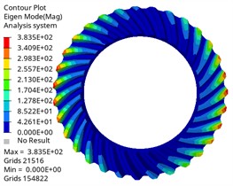
b) Second-order mode shape
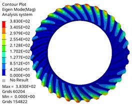
c) Third-order mode shape
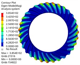
d) Fourth-order mode shape
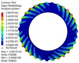
e) Fifth-order mode shape
f) Sixth-order mode shape
The vibration mode analysis reflects the vibration mode of the gear at different natural frequencies. It is shown that the first three vibration modes of the driving gear and the driven gear are the same, and the first one is circular vibration. The second and third order are torsional vibration, which is one of the main sources of gear transmission noise. When the frequency is in the first three order, the gear pair may have resonance phenomenon, leading to the increase of vibration and noise. Higher-order umbrella/folding vibration is related to the bending deformation of gears, which may affect the load distribution on the tooth surface. Its high frequency characteristics show that the gear structure is stiff, which is beneficial to maintain meshing accuracy and reduce dynamic load fluctuation, thus having a positive impact on delaying fatigue damage. By comparing different vibration modes, the gear design can be optimized and potential resonance can be avoided. The results can provide reference for the dynamic performance evaluation of gears under actual working conditions, optimize gear parameters, avoid the matching between natural frequency and working frequency, and improve the reliability and stability of gear transmission system.
5. Conclusions
In this paper, the spiral bevel gear in the differential of Baja off-road vehicle is designed, analyzed and verified. By calculating the key design parameters of spiral bevel gear and establishing three-dimensional modeling, the finite element analysis software is used for contact analysis and modal analysis. The maximum contact stress of the tooth surface is 411.4 MPa. Compared with the allowable contact stress of the material (550 MPa), the safety factor of contact strength reaches 1.34, which should provide sufficient strength margin for the dynamic impact load in the competition. The natural frequency of the gear pair obtained by analysis is much higher than the excitation frequency of the system (32.5 Hz), which avoids the resonance risk and ensures the dynamic stability of the transmission system under complex working conditions, and provides an important basis for optimizing the design, reducing vibration and noise, and improving the stability and reliability of the transmission.
References
-
C. Q. Qi and Y. Gan, “3D digital Design of Gleason spiral bevel gear and its application in automobile differential,” (in Chinese), Automation in Manufacturing, Vol. 33, No. 3, pp. 134–138, 2021.
-
J.-Y. Tang, Z.-H. Hu, L.-J. Wu, and S.-Y. Chen, “Effect of static transmission error on dynamic responses of spiral bevel gears,” Journal of Central South University, Vol. 20, No. 3, pp. 640–647, Mar. 2013, https://doi.org/10.1007/s11771-013-1530-y
-
Q. Wang, C. Zhou, L. Gui, and Z. Fan, “An ease-off based approach to designing a high-order transmission motion for face-milled spiral bevel gears,” International Journal of Vehicle Design, Vol. 81, No. 3/4, p. 241, Jan. 2019, https://doi.org/10.1504/ijvd.2019.111583
-
B. Wang and L. Hua, “Dynamic modal analysis of automotive spiral bevel gears with high rotation speed,” (in Chinese), Automotive Engineering, Vol. 33, No. 5, pp. 447–451, 2011, https://doi.org/10.19562/j.chinasae.qcgc.2011.05.017
-
Y. Mu and X. He, “Design and dynamic performance analysis of high-contact-ratio spiral bevel gear based on the higher-order tooth surface modification,” Mechanism and Machine Theory, Vol. 161, p. 104312, Jul. 2021, https://doi.org/10.1016/j.mechmachtheory.2021.104312
-
Y.-P. Shih, “A novel ease-off flank modification methodology for spiral bevel and hypoid gears,” Mechanism and Machine Theory, Vol. 45, No. 8, pp. 1108–1124, Aug. 2010, https://doi.org/10.1016/j.mechmachtheory.2010.03.010
-
Y.-P. Shih and S.-D. Chen, “A flank correction methodology for a five-axis CNC gear profile grinding machine,” Mechanism and Machine Theory, Vol. 47, pp. 31–45, Jan. 2012, https://doi.org/10.1016/j.mechmachtheory.2011.08.009
-
M. X. Fan, T. J. Wang, and Z. H. Fu, “Research on a four-wheel drive system applied to a small off-road racing car,” (in Chinese), Internal Combustion Engine and Parts, pp. 93–95, 2023, https://doi.org/10.19475/j.cnki.issn1674-957x.2023.18.028
-
Z. H. Jin et al., “Research on characteristics of rubber belt type CVT in Baja racing car,” (in Chinese), Mechanical Transmission, Vol. 46, No. 1, pp. 143–147, 2022, https://doi.org/10.16578/j.issn.1004.2539.2022.01.020
-
Y. H. Chen, “Parametric modeling and Meshing performance analysis of spiral bevel gears,” Southwest Jiaotong University, Chengdu, China, 2023.
-
Y. D. Zong, D. S. Wang, and C. H. Li, “Study on parametric modeling method of spiral bevel gear,” (in Chinese), Machinery, Vol. 39, No. 12, pp. 58–61+73, 2012.
-
Y. Fu, Y. Zhuo, X. Zhou, B. Wan, H. Lv, and Z. Wang, “Theoretical and experimental study on contact characteristics of spiral bevel gears under quasi-static and large loading conditions,” Applied Sciences, Vol. 10, No. 15, p. 5109, Jul. 2020, https://doi.org/10.3390/app10155109
-
Y. Y. Xu, “Parametric modeling and contact analysis of spiral bevel gears,” Shenyang University of Technology, Shenyang, China, 2022.
-
Z. F. Yan, “Study on the performance of four/hexahedral grid in stress analysis of drill pipe joints,” (in Chinese), Coal Mine Machinery, Vol. 41, No. 9, pp. 41–44, 2020, https://doi.org/10.13436/j.mkjx.202009014
-
X. Hou, Z. Fang, and X. Zhang, “Static contact analysis of spiral bevel gear based on modified VFIFE (vector form intrinsic finite element) method,” Applied Mathematical Modelling, Vol. 60, pp. 192–207, Aug. 2018, https://doi.org/10.1016/j.apm.2018.03.021
-
H. Ji, Y. Sun, and C. Tian, “Design and contact analysis of Gleason spiral bevel gears,” (in Chinese), Machine Design, Vol. 36, pp. 89–94, 2019, https://doi.org/10.13841/j.cnki.jxsj.2019.07.016
-
Y. Liu, L. Chen, X. Mao, and D. Shangguan, “A semi-analytical loaded contact model and load tooth contact analysis approach of ease-off spiral bevel gears,” Machines, Vol. 12, No. 9, p. 623, Sep. 2024, https://doi.org/10.3390/machines12090623
-
G. Shashi Kumar and G. B. Krishnappa, “Design and finite element analysis of AISI 4340 alloy steel helical gear,” Materials Today: Proceedings, Vol. 65, pp. 3671–3674, Jan. 2022, https://doi.org/10.1016/j.matpr.2022.06.288
-
Y. Q. Feng, J. Y. Zhao, and S. Q. Chen, “Modal analysis of spiral bevel gear for high power reducer,” (in Chinese), Mechanical Transmission, Vol. 36, No. 3, pp. 78–80, 2012, https://doi.org/10.16578/j.issn.1004.2539.2012.03.020
About this article

The research was supported by the Liuzhou Science and Technology Program (No. 2024AB0401A009), and the Guangxi Science and Technology Program (No. AD23026183).
The datasets generated during and/or analyzed during the current study are available from the corresponding author on reasonable request.
Xuezhong Fu and Zexin Zhou: article conception; Xuezhong Fu and Quansheng Teng: literature search; Xuezhong Fu, Zexin Zhou and Shuping Li: drafted and revised the work; Zexin Zhou: Software; Quansheng Teng and Shuping Li: validation. All authors have read and agreed to the published version of the manuscript
The authors declare that they have no conflict of interest.
