Abstract
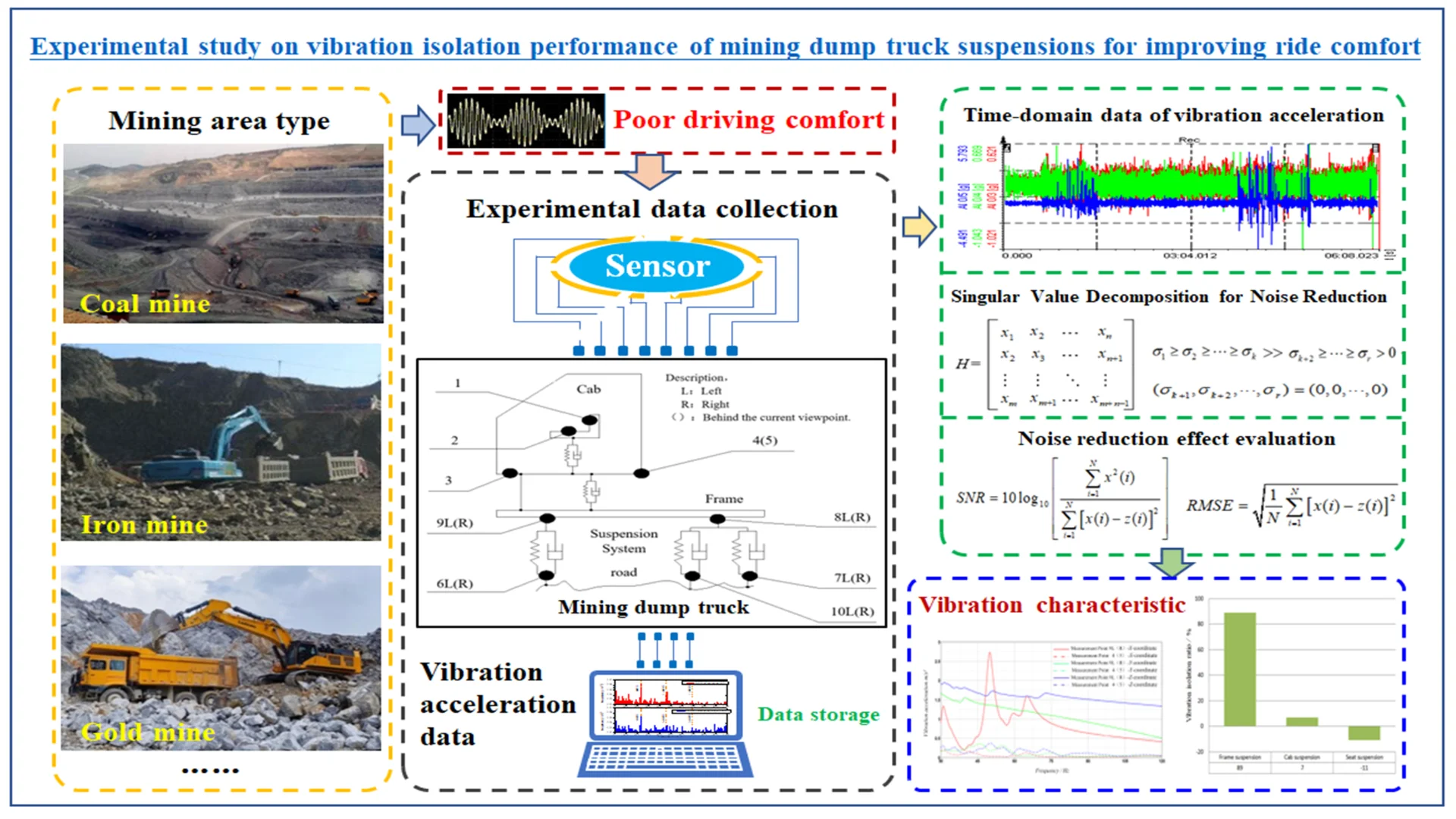
This study addresses the challenge of reducing the transmission of low-frequency road excitation vibrations to the cab of mining dump trucks to enhance ride comfort. Given the harsh working conditions of these vehicles, a novel methodology combining experimental data collection and advanced signal processing techniques was developed. The research established a comprehensive vibration testing program aligned with earth-moving machinery standards, collecting vibration acceleration data under both idling and full-load operation at 35 km/h. To improve data accuracy, Singular Value Decomposition (SVD) was employed to denoise the experimental vibration data, effectively mitigating environmental interference. Subsequent Fourier transform analysis revealed the vibration energy transfer patterns of the vehicle suspension system in the frequency domain. The results indicated a significant vibration isolation rate of 89 % for the frame suspension system, contrasting with only 7 % for the cab suspension system. Notably, the cab seat suspension system was found to amplify low-frequency road excitations. Compared to previous methods, this study innovatively integrates SVD and Fourier transform techniques to provide a more accurate and detailed understanding of vibration transmission. The key result of achieving an 89 % vibration isolation rate for the frame suspension system demonstrates the effectiveness of the proposed methodology. This study offers practical optimization directions for improving suspension system performance and ride comfort in mining dump trucks, outperforming traditional approaches by providing a more comprehensive analysis and actionable insights for vibration isolation. The findings also serve as valuable references for addressing similar engineering challenges in heavy machinery.
Highlights
- Experimental study on driving and riding comfort
- Singular value decomposition for noise reduction
- Evaluation of the vibration isolation performance of the damping system
1. Introduction
In the current era of rapid development of emerging technologies, mineral resources and energy serve as the lifeblood of national industrial development, and the extraction of these resources relies heavily on mining dump trucks. As a vital engineering transportation vehicle, the mining dump truck operates in harsh working conditions. The vibration characteristics of its cab directly affect the driver's operational comfort and work efficiency. In recent years, with the continuous expansion of the scale of mining operations, the performance requirements for mining dump trucks have been increasingly elevated, among which the issue of cab vibration control has garnered widespread attention. The development of mining dump trucks is hindered by high technical difficulty, the need for substantial capital investment, and a lengthy research and development cycle, resulting in a scarcity of relevant studies [1, 2]. In this context, aligned with the strategic principle of advancing science and technology to "face the global frontiers of science and technology, serve the main battlefield of the economy, address major national needs, and safeguard people’s lives and health," the advancement of mining dump truck technology has been prioritized as a critical national demand.
China’s independent research and development of mining dump trucks in the industrial and mining sectors spans only five to six decades. Moreover, domestic capabilities in R&D and manufacturing processes still lag significantly behind those of foreign counterparts [3, 4]. Against the backdrop of intense market competition for similar products and a lack of shared technical resources, these limitations have severely constrained the development and technological upgrading of China’s industrial and mining transportation vehicle sector. As a result, the domestic market for such vehicles has long been dominated by foreign counterparts [5-8]. Additionally, increases in load capacity and the stiffness of vehicle suspension systems have progressively degraded the ride comfort of mining dump trucks. Prolonged exposure to such harsh vibration environments compromises driving stability, reduces operational efficiency, and may even lead to severe casualties [9, 10].
Mining dump trucks usually travel on rugged mine roads. The low-frequency excitation vibrations from the road are transmitted to the cab through the vehicle’s suspension system, resulting in high vibration levels inside the cab, which seriously affect the driver’s comfort. Studies have shown that the vibration level inside the cab is closely related to the driver's degree of fatigue and work efficiency. Therefore, how to effectively reduce the vibration level inside the cab and improve ride comfort is an important issue in the design and improvement of mining dump trucks.
During the theoretical research phase, the dynamic characteristics of the vehicle are commonly studied using a quarter-car model or a finite element model of the cab suspension system, which is a widely adopted general method [11, 12]. Although the general method can provide theoretical support in some cases, it may not fully reflect the complexity of the actual working conditions in the mining area. In practical applications, the performance of the suspension system is influenced by a variety of factors, including the mining environment, material properties, structural design, load conditions, and operator experience. Therefore, the majority of researchers believe that experimental data can more directly reflect the isolation effect in practical applications. The main objective of this study is to verify the isolation effect of the suspension system through experiments, hoping to directly demonstrate the performance of the suspension system with experimental data rather than relying on predictions from theoretical models. The experimental results have already well supported the research objective, that is, the isolation effect of the suspension system in practical applications.
Extensive research has been conducted by scholars, both domestic and international in the field of vibration studies on mining dump trucks. Early investigations primarily focused on the vibration characteristics of the vehicle suspension system. By establishing vehicle dynamics models, the impact of suspension system parameters on vibration response was examined. For instance, M. J. Rahimdel et al. [13, 14] developed a multi-body dynamics model to analyze the vibration characteristics of the suspension system in mining dump trucks and proposed methods for optimizing suspension system parameters. However, these studies were largely based on theoretical models and lacked experimental validation under actual working conditions. In recent years, with the advancement of testing technologies, an increasing number of studies have begun to employ experimental methods to investigate the vibration characteristics of mining dump trucks. By installing accelerometers at key locations on the vehicle, they measured the vibration acceleration data under different operating conditions. These studies have provided significant experimental evidence for vibration control in mining dump trucks.
Extensive research has also been conducted by scholars in the field of vibration control technology. Traditional vibration control methods have primarily focused on the design and optimization of suspension systems, with adjustments to the stiffness and damping parameters of the suspension system to enhance vibration isolation effects. Zhang et al. [15] investigated the optimization of damping hole parameters for the hydro-pneumatic suspension system in mining trucks under variable load conditions. By optimizing the damping hole parameters, the vibration isolation performance of the suspension system is significantly improved, thereby enhancing the ride comfort and driving stability of the mining trucks. With the development of intelligent control technologies, advanced vibration control methods have also been applied to mining dump trucks. For instance, Wang et al. [16] investigated the stability control of four-wheel steering mining trucks and proposed an optimal direct yaw moment allocation method based on fuzzy rules. This method effectively enhances the yaw stability of mining trucks under various working conditions, reduces the risk of vehicle rollover, and improves driving safety. These studies have provided new ideas and methods for vibration control in mining dump trucks. Parida et al. [17, 18] Sandwich-structures are widely used in structural applications for their damping nature, attributed to their viscoelastic or honeycomb core. However, the geometry and material variety of the honeycomb core greatly influence the structural dynamics. The aforementioned vibration damping methods and structures provide a concept and reference for the selection of vibration damping devices and the design of vibration damping structures in mining dump trucks.
In this study, an experimental approach was employed to establish a vibration testing procedure for mining dump trucks in accordance with earth-moving machinery standards. Accelerometers were installed at key locations on the vehicle to measure the vibration acceleration data at the measurement points. Subsequently, Singular Value Decomposition (SVD) was applied to the experimental vibration data for noise reduction, effectively minimizing the impact of environmental interference on the target characteristics. Finally, the denoised time-domain vibration data were subjected to Fourier transform to analyze the vibration energy transfer patterns of the vehicle suspension system in the frequency domain. This study combines theoretical research with experimental methods to collect full-vehicle vibration data from benchmark industrial and mining vehicles [19, 20]. A systematic data processing approach – encompassing signal denoising, feature extraction, and target characteristic identification – is employed to mitigate interference from complex engineering environments during data analysis. By identifying the dominant vibration characteristics affecting ride comfort in mining dump trucks, and integrating theoretical and experimental findings, this research establishes ride comfort metrics. These outcomes aim to precisely guide the development of vibration-damping systems for industrial and mining vehicles, ensuring practical applicability and performance optimization.
The innovation of this study is twofold. It involves a systematic investigation of the vibration characteristics of mining dump trucks using experimental methods and an in-depth analysis of vibration data using techniques such as Singular Value Decomposition (SVD) and Fourier transform. This approach not only effectively mitigates the influence of environmental interference on the experimental data but also clearly elucidates the vibration energy transfer patterns of the vehicle suspension system in the frequency domain. Moreover, the findings of this study provide a significant reference for optimizing the vibration isolation performance of the suspension system in mining dump trucks.
2. Experimental setup
2.1. Experimental conditions
In accordance with national standards and regulations for vehicle vibration testing, the experimental conditions were established as summarized in Table 1.
The real-life experiments were conducted at a mine site in Longyan City, Fujian Province, China. Prior to this experiment, detailed surveys had been carried out with drivers of this type of vehicle. It was concluded that when the vehicle climbs slopes at a speed of 10 km/h under full-load and no-load conditions, the overall vibration exposure is relatively moderate and has an insignificant impact on the comfort of passengers and drivers. Meanwhile, the low-speed climbing experiments require specific slope settings. The experimental site was located at the front - line production area of the actual mine, which could not provide standard experimental conditions. Therefore, the climbing condition at a speed of 10 km/h was not included in the experimental design of this study.
Located in the southeastern mountainous region of China, the area is characterized by a natural environment with frequent rainfall, dense fog, and slippery road surfaces. In consideration of the safety of personnel and vehicles, the mine site safety management authorities have imposed a maximum driving speed limit of 40 km/h. Therefore, within the management restrictions of this mine site, the current experiment did not involve high-speed no-load conditions (≥ 40 km/h) for the vehicle.
The company, based on its prior research, has identified that the vehicle vibration under no-load and full-load conditions at a speed of 35 km/h is relatively complex. Additionally, in order to enhance the efficiency of vehicle product improvement and shorten the improvement cycle for the company, the focus of this experimental test was required to be concentrated on the condition of 35 km/h. This speed is the most common in actual mining operations, and the data obtained at this speed hold significant reference value for the study of vehicle ride comfort. Although the experimental design in this study did not cover two common working conditions in actual mining operations, namely, heavy-load low-speed (≤ 10 km/h climbing) and high-speed no-load (≥ 40 km/h), the existing experimental data still provide certain reference value for actual mining operations, even without involving these two conditions.
Table 1Experimental conditions
Category | Description |
Road conditions | Test road features steep slopes, sharp turns, slippery surfaces, and uneven terrain. Total length: approximately 3 km |
Wind speed | ≤ Grade 3 (3.4-5.4 m/s) |
Weather | Cloudy, Temperature 19 °C |
Vehicle condition | (1) Vehicle condition complies with technical design specifications |
(2) Tire pressure meets technical design requirements | |
(3) Load capacity: Approximately 55 tons | |
Occupant-seat system | Two adults (1 driver, 1 test personnel) |
With height: 1.8±0.05 m and weight: 65±0.5 kg | |
Speed | 35 km/h (Most commonly used vehicle speed) |
Excitation | Random vibration based on actual mine road profiles |
2.2. Experimental standards
2.2.1. Test standards
Based on the operational conditions and structural characteristics of the mining dump truck, the layout of measurement points for this experiment was designed in compliance with the methods specified in [21].
2.2.2. Evaluation criteria
The measured vibration acceleration data were evaluated according to the computational methodology outlined in [22]. This standard verifies whether the vibration exposure levels of the mining dump truck meet the ride comfort requirements mandated by national regulations.
2.3. Experimental methodology
2.3.1. Test conditions
Tests were conducted on the mining dump truck under both unloaded and fully loaded conditions, strictly adhering to the experimental standards.
2.3.2. Measurement point layout
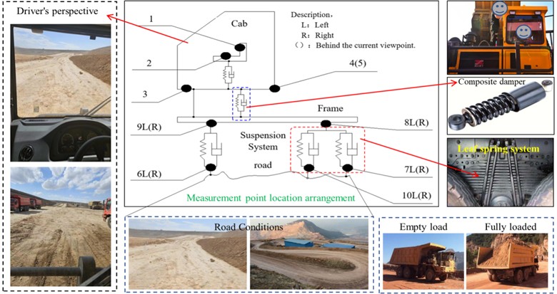
In accordance with the experimental objectives and relevant standards, measurement points were strategically positioned. Specific arrangements are illustrated in Fig. 1, where positions numbered 1-10 denote the measurement locations.
Fig. 1Layout of measurement points
2.3.3. Experimental site
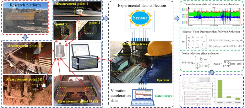
The experiment was conducted in a real-world mining area. The mining dump truck is primarily used for transporting waste soil and ores, as well as site transfers between operational zones. The operating environment of the mining dump truck is shown in Fig. 2.
Fig. 2Experimental process planning
2.3.4. Experimental equipment
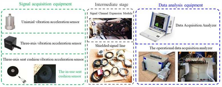
The main equipment used in this experiment includes a multi-channel vibration signal acquisition analyzer and single-axis/tri-axial vibration acceleration sensors, as shown in Fig. 3.
Fig. 3Experimental data acquisition equipment
The statements in Figs. 1-3: This experiment was conducted on behalf of Shaanxi Tongli Heavy Industry Co., Ltd. All the photos in the article were taken by the author, Ma Na. The shooting location was the mining area in Longyan City, Fujian Province, China. The shooting time was mid-October 2024.
3. Experimental data processing
3.1. Time-domain data of vibration acceleration
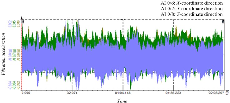
According to the experimental plan, vibration acceleration data were collected at each test location. Due to the large number of measurement points set up in this experiment and the limited space in the paper, not all data are presented. Only the experimental data from the measurement points in direct contact with the driver are provided, as the footrest and seat cushion positions directly expose the driver and passengers to the vibration field. For example, the vibration experimental data from the footrest and seat cushion positions in the cab are shown in Figs. 4-5, respectively. In the figures, AI 0/3, AI 0/4, and AI 0/5 represent the vibration acceleration experimental data in the , , and directions at the seat cushion position, while AI 0/6, AI 0/7, and AI 0/8 represent the vibration acceleration experimental data in the , , and directions at the footrest position in the cab.
Fig. 4Time-domain data of vibration acceleration at the seat cushion position
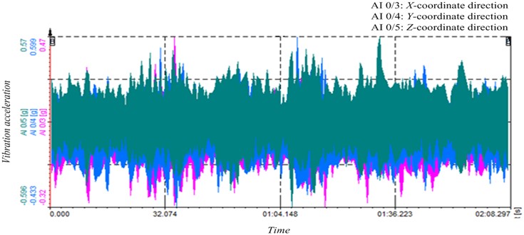
Fig. 5Time-domain data of vibration acceleration at the cab floor mat
3.2. Denoising of experimental data
3.2.1. Denoising methods
During the experiment, the vibration acceleration data at each measurement point were significantly affected by the surrounding environment, and the main vibration characteristics of the cab were easily drowned out by the ambient white noise. In order to eliminate the impact of interference sources, identify the main causes of cab vibration in mining dump trucks, and clarify the direction for improving the ride comfort of the cab.
At present, there are many methods for signal denoising, such as wavelet threshold denoising, moving average method, singular value decomposition method, median method, standard deviation method, and Kalman filter. Extensive research has shown that the singular value decomposition method is not affected by the physical dimensions of various factors, and it can efficiently separate the main vibration characteristic information from the interference information based on the distribution of the main characteristic information in the phase space matrix. This advantage has enabled the singular value decomposition denoising method to be widely used in various fields [23, 24].
The primary objective of this study was to explore the effectiveness of the SVD denoising method in specific application scenarios. Due to limitations in resources and time, the focus was concentrated on the practical validation of the SVD denoising method, rather than extending to comparisons with other methods. Given the working characteristics of mining dump trucks, the comfort of these vehicles is mainly significantly affected by low-frequency vibrations. The experimental data in this study were primarily focused on the processing of low-frequency signals. High - frequency vibration components, in the complex mining environment, are blended into the mining operation environment in the form of noise. Compared with the impact of low-frequency vibrations on vehicle ride comfort, their influence is less significant. Therefore, data on high-frequency components received relatively less attention in this experimental study. As a result, at this stage, a comprehensive assessment of the risk of over-smoothing of high-frequency components has not been conducted.
Therefore, based on the above research results, this paper also selects the singular value decomposition method as the denoising method for the experimental data in this study.
3.2.2. Denoising principle
The method of performing orthogonalization calculation on a real matrix , regardless of whether its rows and columns are related or not, there must exist two matrices, and , such that Eq. (1) holds:
where is the singular value matrix of the real matrix , and , are the singular values of the real matrix , and , :
where represents the dimensions of the matrix.
Let’s consider a set of discrete random time-domain signals , whose signal sequence can be represented by . Using the singular value decomposition method to construct a Hankel matrix, and decomposing it yields the singular values shown in Eq. (3):
Then, the abrupt point of the singular values in Eq. (3) is identified, the singular values before point are retained and denoted as , and all the singular values after point are set to 0, as shown in Eq. (4):
Finally, among the retained singular values, the order corresponding to the peak of the singular value energy spectrum is identified, and then the singular values are reconstructed according to this order. The signal obtained after reconstruction is the main vibration characteristic signal after denoising.
3.2.3. Evaluation of denoising effect
After denoising the vehicle vibration experimental data using Singular Value Decomposition (SVD), the Signal-to-Noise Ratio (SNR) and Root Mean Square Error (RMSE) methods are commonly employed to quickly and effectively evaluate the denoising effect. In this experimental study, the primary objective is to rapidly guide the improvement direction of the target vehicle suspension system based on the experimental results, emphasizing speed and effectiveness. Additionally, these methods are computationally simple and provide intuitive results, making them commonly used indicators for evaluating denoising effects. Therefore, in this study, the evaluation of denoising effect using SNR and RMSE methods can meet the requirements of the experimental research.
The SNR is the ratio of signal power to noise power, typically expressed in decibels (dB). The calculation formula is shown in Eq. (5):
where represents the original signal, denotes the denoised signal, and is the number of data points.
The RMSE is the square root of the mean of the squares of the errors between the denoised data and the original signal. The calculation formula is shown in Eq. (6):
where represents the original signal, denotes the denoised signal, and is the number of data points.
3.2.4. Denoising results
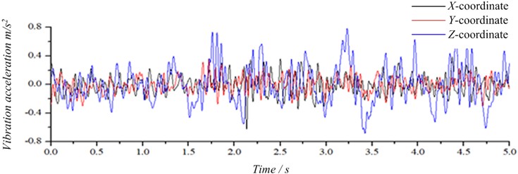
All the vibration acceleration data at the measurement points in this experiment were denoised using the singular value decomposition method, and the characteristic signals after denoising were obtained, which laid the foundation for the subsequent research on the vibration characteristics of the cab. The time-domain signals of the experimental data at the cab seat cushion and floor mat after denoising by the singular value decomposition method are shown in Figs. 6-7. From Fig. 6, it can be seen that the vertical vibration amplitude at the seat is the largest, followed by the lateral vibration amplitude, and the front - back vibration amplitude is the smallest. From Fig. 7, it can be seen that the vertical vibration amplitude at the cab floor mat is the largest, followed by the lateral vibration amplitude, and the front-back vibration amplitude is the smallest. This indicates that the vibration characteristics at the cab floor mat and the seat are similar. In addition, from Fig. 7, it can be seen that the vertical vibration amplitude at the cab floor mat is much higher than that at the seat cushion, which indicates that the seat damping system has a certain positive vibration-isolating effect.
Fig. 6Time-domain data of vibration acceleration after noise reduction at the seat cushion
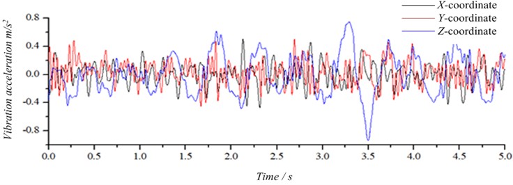
Fig. 7Time-domain data of vibration acceleration after noise reduction at the driver’s cabin foot mat
3.2.5. Noise reduction evaluation
After applying the SVD method for denoising, the evaluation of the denoising effect is shown in Table 2.
Table 2Valuation of denoising effect using SVD
Measurement point locations | SNR | RMSE |
Seat cushion | 6.07 dB | 0.4067 |
Foot mat | 9.16 dB | 0.2273 |
The higher the SNR after denoising, the better the denoising effect. Typically, an increase in SNR of more than 3 dB is perceptible to the human ear as a significant reduction in noise. Additionally, the smaller the RMSE, the closer the denoised signal is to the original signal, indicating a better denoising effect. Based on the values of SNR and RMSE in Table 2, it can be concluded that the denoising effect achieved using SVD in this study is satisfactory. The denoised vibration signals meet the requirements for the experimental research.
4. Vibration characteristics analysis of the cab mounting system
4.1. Vibration source characteristics analysis
4.1.1. Engine excitation
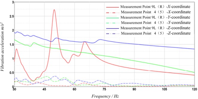
Under idle conditions of the experimental vehicle, the dynamic excitation generated by the engine operation is the primary source of cab vibration. Fig. 8 shows the vibration response characteristics curve of the mining dump truck’s cab mounting system under idle conditions. In the figure, the active end corresponds to Measurement Point 9, while the passive end corresponds to Measurement Point 4 (5). Under the influence of the engine’s dynamic excitation, the vibration amplitude at Measurement Point 9 is significantly higher than that at the passive end (Points 4/5), indicating that the cab mounting system exhibits notable vibration isolation effectiveness.
Additionally, within the frequency range of 30-70 Hz, the vibration in the -direction at Measurement Point 9 (active end) is relatively complex, causing a short-term “nodding” sensation in the cab. Above 70 Hz, the vibration acceleration in the -direction decreases below 1 m/s2, with the amplitude gradually stabilizing. However, while the vibration characteristics in the - and -directions at Measurement Point 9 are generally synchronized, the lateral (side-to-side) vibration amplitudes are the lowest, though their acceleration values remain above 0.5 m/s2. At the passive end (Measurement Point 4/5), which reflects the vibration after isolation by the cab mounting system, the vibration acceleration values are all below 0.4 m/s2, as shown in Fig. 8. Within the 30-70 Hz range, the lateral swaying vibration of the cab becomes relatively noticeable.
The vibration acceleration of measuring point 9L(R) in the coordinate direction shows the most significant variation, with a distinct peak occurring at approximately 45 Hz. Subsequently, the vibration acceleration decreases gradually with increasing frequency, exhibiting a downward trend. In contrast, the vibration acceleration of measuring point 4(5) in the coordinate direction is relatively low and exhibits minimal variation across the frequency range, maintaining a relatively stable level.
In the coordinate direction, the vibration acceleration of measuring point 9L(R) also decreases gradually with increasing frequency and presents a minor peak at around 75 Hz. Similarly, the vibration acceleration of measuring point 4(5) in the coordinate direction decreases gradually with increasing frequency, but the overall vibration acceleration is lower. In the coordinate direction, the vibration acceleration of both measuring points 9L(R) and 4(5) shows a similar trend, decreasing gradually with increasing frequency. A minor peak is observed at 75 Hz, but the overall vibration acceleration remains relatively low.
Overall, the vibration acceleration of measuring point 9L(R) in the coordinate direction is the highest, with a distinct peak at 45 Hz. In contrast, the vibration acceleration of measuring point 4(5) is relatively low across all coordinate directions and exhibits minimal variation. As frequency increases, the vibration acceleration in the and coordinate directions for both measuring points 9L(R) and 4(5) decreases gradually. From these vibration curves, it can be concluded that the vehicle cabin suspension system provides effective vibration reduction under the current operating conditions. Moreover, these analysis results are of significant reference value for understanding the vibration characteristics of different measuring points at various frequencies and for the vibration analysis of the suspension system.
Fig. 8Vibration response characteristics of the cab mounting system
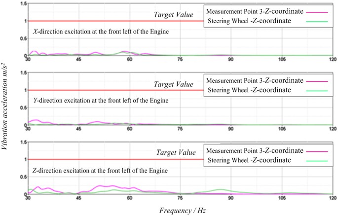
Based on the vibration conditions at the internal measurement points of the cab shown in Fig. 9, it can be observed that the vibration amplitudes at positions in contact with the human body, such as the seat cushion (seat pan) and steering wheel, are significantly below the vibration target value of 1 m/s2. At these two locations, the vibration accelerations in the -, -, and -directions are all below 0.15 m/s2, with the -direction exhibiting the highest vibration amplitude. Between the seat cushion and steering wheel measurement points, the vibration at the seat cushion dominates, which is the main cause of discomfort related to the cab’s ride smoothness.
Fig. 9Vibration response characteristics inside the cab
4.1.2. Road excitation
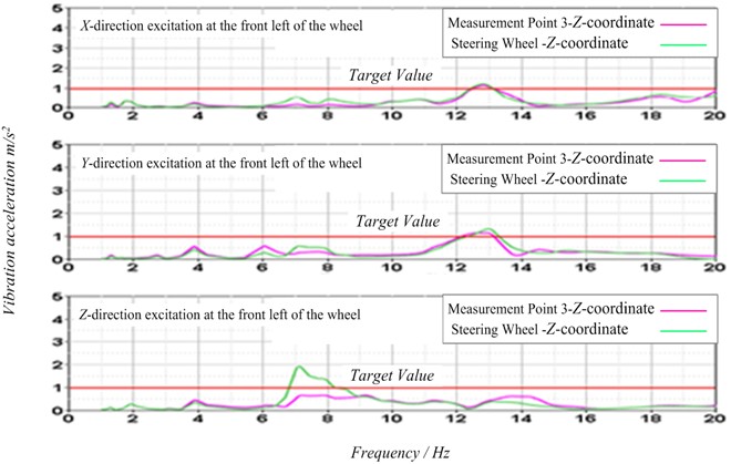
The driving comfort of the cab of the dump truck is mainly affected by the driving excitation of the road surface in the mining area. Moreover, cab vibration is the vibration response caused by road excitation and engine excitation at the same time. In addition, the cab of the mine dump truck in this experiment is side-mounted, and the cab is roughly installed on the frame of the left front wheel. Therefore, the vibration energy of the left front wheel is directly transmitted to the cab mounting system through the frame mounting system, so the road excitation of the left front wheel most of the vibration energy directly dominates the driving comfort of the cab.
According to Fig. 10, the relationship curve of vibration characteristics between the seat soleplate (cushion) and the steering wheel inside the cab is shown. It can be obtained from the figure: The vibration in the direction of the test position of the seat cushion and the steering wheel inside the cab at 13 Hz is greatly affected by the and directions of the road excitation and the engine excitation. The vibration amplitude of the test point inside the cab exceeds the target value by 1 m/s2, but only within 0.4 m/s2 of the target value. This phenomenon shows that the vibration in the cab area is obviously affected by the engine excitation. At 7 Hz, the vibration of the excitation source in the direction affects the inner cab area, so that the vibration amplitude at the steering wheel reaches 2 m/s2, and the vibration amplitude of the steering wheel is larger. The reason for this phenomenon is that the steering wheel and the directional drive shaft are directly connected to the front axle, and the road excitation source is isolated from the transmission chain of the steering wheel without passing through the frame mounting system and the cab mounting system, and the vibration energy is directly input to the steering wheel. As a result, the vibration at the steering wheel is highly susceptible to the influence of low-frequency excitation on the road surface.
Fig. 10Vibration response characteristics inside the cab
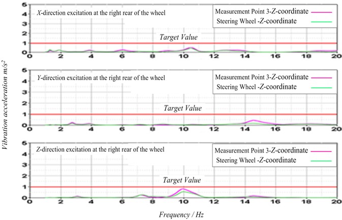
The vibration response shown in Fig. 11 is to study the vibration isolation of the road’s low-frequency excitation source transmitted from the left rear wheel to the cab suspension system. It can be seen from the figure that the vibration characteristics of the excitation source in the , and directions do not exceed the target range of 1 m/s2 for the amplitude of the seat soleplate and the steering wheel in the cab, but the vibration in the direction of the excitation source at 10 Hz resonates with the test area in the cab in a small range, and its peak value is 0.8 m/s2. In other frequency bands, the vibration amplitude of the seat soleplate and steering wheel in the cab is less than 0.1 m/s2, indicating that the vibration of the left rear wheel has little influence on cab ride comfort.
4.2. Analysis of the vibration characteristics of the cab
4.2.1. Analysis of vibration transmission pathways
There are three main transmission paths of vibration source in the cab of mining dump truck: the first is road excitation→front tire→frame mounting system→cab mounting system→seat mounting system; The second is engine excitation→engine damping support→frame mounting system→cab mounting system→seat mounting system; The third is from road excitation→rear tires→frame mount system→cab mount system→seat mount system. The self-excited vibration generated by other areas or components is only noise, which does not affect the ride comfort, but has an impact on the ride comfort. In the complex operating environment of mining area, it is difficult to meet the requirements of driving comfort with the existing technology. Therefore, it is not considered in this paper.
Fig. 11Vibration response characteristics inside the cab
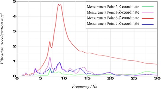
The cab of the mining dump truck belongs to the left offset type and is installed above the left front wheel. The dynamic excitation of the cab mainly comes from the low-frequency excitation of the road surface. In addition, the driving smoothness of the cab of the mining dump truck mainly depends on the vibration amplitude in the direction of the cab. Fig. 12 shows the dynamic response curve of the complete suspension system of mining dump truck in the Z direction. According to the figure, the vibration amplitude of the left front wheel (measuring point 6), frame (measuring point 9), cab support (measuring point 3), and cab base (measuring point 2) in the direction is the largest at 8 Hz, and its peak value reaches 4.81 m/s2. The vibration amplitude of cab support and cab base is the same, and the vibration amplitude of frame is the least. It shows that under the current working condition, the vibration damping of the frame plate spring suspension system is good, while that of the cab and seat suspension is better. Most of the overall vibration amplitude of the cab is below 1 m/s2. Although the ride comfort of the cab is not ideal, the cab suspension and seat suspension system can attenuate the low-frequency excitation vibration energy of the road surface by more than 80 %.
Measurement Point 6 – Coordinate (red solid line) exhibits a minor peak at 7 Hz, indicating a slight increase in vibration acceleration at this frequency. However, the most significant change occurs at 9 Hz, where the vibration acceleration reaches its maximum value, exceeding 4.5 m/s2. As the frequency increases, the vibration acceleration gradually decreases, showing a downward trend.
Measurement Point 9 – Coordinate (blue solid line) has a minor peak at 6 Hz, but the vibration acceleration is much lower than that of Measurement Point 6. It reaches a smaller peak at 9 Hz, with a vibration acceleration slightly above 1 m/s2. As the frequency increases, the vibration acceleration also gradually decreases.
Measurement Point 3 – Z Coordinate (purple solid line) shows a minor peak at 7 Hz, with a vibration acceleration slightly above 1 m/s2. It reaches a smaller peak at 9 Hz, with a vibration acceleration slightly below 1 m/s2. As the frequency increases, the vibration acceleration gradually decreases.
Measurement Point 2 – Coordinate (green solid line) has relatively low vibration acceleration across the entire frequency range, with minimal variation. There is a minor peak at approximately 7 Hz, but the vibration acceleration is much lower than that of the other measurement points. As the frequency increases, the vibration acceleration gradually decreases.
Overall, Measurement Point 6 has the highest vibration acceleration in the coordinate direction, with a significant peak at 9 Hz, which may indicate that this frequency is one of the resonant frequencies of the dump truck. Measurement Points 9 and 3 have lower vibration accelerations in the coordinate direction, with smaller peaks at 9 Hz. Measurement Point 2 has the lowest vibration acceleration in the coordinate direction and exhibits minimal variation across the entire frequency range.
The analysis results indicate that under the excitation of the road surface, the suspension systems of this type of mining dump truck have all played a role in vibration reduction. However, the vibration reduction effect of the cab suspension system is not significant, and its vibration reduction structure needs to be optimized and improved in the future.
These analysis results are of great reference value for the vibration analysis of mining dump trucks. In particular, the significant peak of Measurement Point 6 at 9 Hz may indicate that this frequency is one of the resonant frequencies of the dump truck, which requires further analysis and treatment to avoid excessive vibration at this frequency, thereby affecting the stability and safety of the vehicle. At the same time, the variation of vibration acceleration at other measurement points also needs to be considered comprehensively to fully understand the vibration characteristics of the dump truck.
Fig. 12Vibration transmission characteristics of the mounting system
4.2.2. Analysis of Low-frequency characteristics
The amplification of low-frequency vibrations (1-3 Hz) in seat suspension systems is an important research topic because it directly affects ride comfort and passenger health. According to international standards and references [25-27], low-frequency vibrations have particularly significant physiological and psychological effects on humans. These effects are mainly manifested in the following ways:
Low-frequency vibrations can cause resonance of internal organs, leading to discomfort and even long-term health issues. They can cause fatigue in bones and muscles, resulting in muscle tension and pain. They can interfere with the human sense of balance, leading to motion sickness (such as car sickness), especially within the frequency range of 1-3 Hz. Additionally, low-frequency vibrations can significantly reduce ride comfort, causing passengers to feel uncomfortable and irritable. Long-term exposure to low-frequency vibrations may affect passengers' work efficiency and concentration, increasing the likelihood of accidents.
Based on the results shown in Figs. 9-12, the maximum vibration acceleration within the low-frequency range (1-3 Hz) is less than 0.1 m/s2. Moreover, the probability of the vehicle operating within this low-frequency vibration range is relatively low. Therefore, low-frequency vibrations (1-3 Hz) are not the main factor affecting ride comfort in this experimental study.
4.3. Vibration isolation analysis of the suspension system
The measurement of vibration isolation rate is based on the amplitude ratio of the input vibration to the output vibration. The vibration isolation rate (VIR) is calculated using Eq. (7):
where represents the amplitude of the input vibration, represents the amplitude of the output vibration.
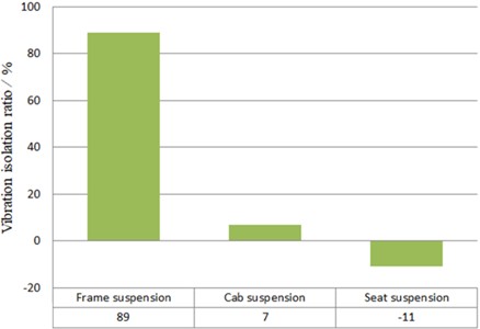
According to the calculation method and evaluation standard in [22], the vibration isolation of each mounting system as shown in Fig. 13 is obtained. It can be seen from the figure that the vibration isolation rate of the frame suspension system of the mining dump truck is 89 %, that of the cab suspension system is 7 %, and that of the cab seat suspension system is –11 %. The analysis shows that the isolation of the frame suspension system of the mine dump truck is ideal under the current working condition, and the isolation of the cab suspension system still needs to be improved. The seat suspension system has the worst vibration isolation, and the seat suspension system amplifies the vibration energy under the current working condition, indicating that the overall stiffness of the seat suspension system is small.
Fig. 13Vibration isolation performance of each mounting system
5. Conclusions
In this paper, an experimental study is carried out on the ride comfort of a kind of mining dump truck with a cab side, and the main reasons affecting cab ride comfort are found out. Through this experimental study, the following conclusions are drawn:
1) According to the relevant standards of mining dump trucks, combined with the calculation methods and experimental conditions of the relevant standards of highway passenger vehicles, the experimental scheme suitable for this study is set up.
2) According to the operating environment and structural characteristics of the mining dump truck, as well as the noise reduction requirements of the vibration acceleration experimental data, it is found that the singular value decomposition noise reduction method can better meet the noise reduction requirements.
3) Under the action of high frequency engine excitation (idle speed), the vibration characteristics of the cab are studied, and it is concluded that the overall “nodding” vibration of the cab is relatively obvious between 30 Hz and 70 Hz under this working condition. In other frequency bands, the vibration amplitude at the test point of the cab is more stable.
4) Under the action of low-frequency excitation on the road surface, the vibration energy transfer characteristics are studied from the left front wheel and the left rear wheel, respectively. Through research, it is concluded that the low-frequency excitation on the road passes the vibration energy of the left front wheel into the higher part of the cab suspension system. The influence of the vibration of the excitation source in the direction on the interior area of the cab at 7 Hz, which makes the vibration amplitude at the steering wheel reach 2 m/s2, is the main reason affecting the ride comfort of the cab.
5) Based on the above research, the vibration isolation characteristics of the vehicle mounting system are studied. It is concluded that the vibration isolation of the frame suspension system is the best under experimental conditions, and the vibration isolation of the cab suspension system is the second. The cab seat suspension system has an amplified effect on vibration energy.
Additionally, the primary objective of this study is to investigate the ride comfort of mining dump trucks under conventional working conditions in the complex environment of a mine site through testing experiments. By conducting this experimental research, we aim to understand the stiffness and damping characteristics of various suspension systems of mining dump trucks under common working conditions in order to enhance ride comfort. Therefore, the focus of this study is solely on obtaining the stiffness and damping characteristics of the suspension systems under these common working conditions. The improvement of ride comfort based on the results of this study will be addressed in subsequent tasks. Consequently, the optimization direction of "adjusting suspension stiffness," identified during the research process as a potential improvement strategy, was not thoroughly validated in this study due to task requirements and time constraints. Thus, the conclusion section of this experiment explicitly states that this direction will be a key focus for in-depth investigation in future work.
Suspension stiffness is one of the key factors affecting vehicle dynamic performance, and its adjustment can significantly impact vehicle handling stability and comfort. Typically, by adjusting suspension stiffness, key parameters such as vehicle roll angle and body acceleration can be optimized under different working conditions, thereby enhancing the overall performance of the vehicle. Therefore, the findings of this study hold significant theoretical and practical value in this regard and warrant further exploration in future work.
References
-
J. Zhao, X. Ren, Z. Dong, and T. Liu, “Optimization design of double wishbone front suspension parameters for large mining dump truck and analysis of ride comfort,” Applied Sciences, Vol. 14, No. 5, p. 1812, Feb. 2024, https://doi.org/10.3390/app14051812
-
A. Moniri-Morad and J. Sattarvand, “A comparative study between the system reliability evaluation methods: case study of mining dump trucks,” Journal of Engineering and Applied Science, Vol. 70, No. 1, pp. 1–17, Aug. 2023, https://doi.org/10.1186/s44147-023-00272-y
-
D. V. Ha, L. van Quynh, and L. X. Long, “Performance analysis of a mining dump truck ride comfort with a hydro-pneumatic suspension system under different operating conditions,” in Lecture Notes in Networks and Systems, Cham: Springer International Publishing, 2022, pp. 790–797, https://doi.org/10.1007/978-3-031-22200-9_83
-
X. Liu, G. Wang, X. Suo, T. Du, W. Wang, and C. Zhang, “Modeling and performance analysis of a hydraulically interconnected suspension for tri-axle mining dump trucks considering pitch-roll resistance,” Journal of Mechanical Science and Technology, Vol. 39, No. 2, pp. 483–495, Jan. 2025, https://doi.org/10.1007/s12206-025-0101-0
-
R. Parreira, J. Meech, and M. Silva, “Autonomous haulage systems in open-pit mining: a comprehensive review of technology and implementation challenges,” Mining, Metallurgy and Exploration, Vol. 40, No. 2, pp. 345–367, 2023.
-
Zhang, L., Wang, Y., Liu, and H., “Multi-sensor fusion and deep learning for autonomous mining trucks in dynamic environments,” IEEE Transactions on Intelligent Transportation Systems, Vol. 23, No. 8, pp. 12456–12470, 2022.
-
A. Gustafson, A. Khajepour, and S. L. Waslander, “Path planning and control of autonomous mining vehicles under uncertain terrain conditions,” Journal of Field Robotics, Vol. 38, No. 5, pp. 789–812, 2021.
-
M. A. Sotelo, M. Bergerman, and C. H. C. Ribeiro, “Autonomous navigation of heavy-duty vehicles in mining environments: a survey of current trends and future directions,” Robotics and Autonomous Systems, Vol. 121, p. 103261, 2019.
-
Y. Xu et al., “Automatically identifying the vegetation destruction and restoration of various open-pit mines utilizing remotely sensed images: Auto-VDR,” Journal of Cleaner Production, Vol. 414, p. 137490, Aug. 2023, https://doi.org/10.1016/j.jclepro.2023.137490
-
J. Tatsuno and S. Maeda, “Effect of whole-body vibration exposure in vehicles on static standing balance after riding,” Vibration, Vol. 6, No. 2, pp. 343–358, Apr. 2023, https://doi.org/10.3390/vibration6020021
-
L. X. Long, T. T. Hưng, N. V. Tuấn, and L. Hải, “Ride performance analysis of a mining dump truck using hydro-pneumatic and rubber suspension systems under different road surface conditions,” Journal of Military Science and Technology, No. FEE, pp. 183–189, Dec. 2023, https://doi.org/10.54939/1859-1043.j.mst.fee.2023.183-189
-
R. Jiao, V. Nguyen, and V. Le, “Ride comfort performance of hydro pneumatic isolation for soil compactors cab in low frequency region,” Journal of Vibroengineering, Vol. 22, No. 5, pp. 1174–1186, Aug. 2020, https://doi.org/10.21595/jve.2020.21345
-
M. J. Rahimdel, M. Mirzaei, J. Sattarvand, and S. H. Hoseinie, “Health risk of whole body vibration in mining trucks during various operational conditions,” Journal of Central South University, Vol. 24, No. 8, pp. 1808–1816, Sep. 2017, https://doi.org/10.1007/s11771-017-3589-3
-
M. J. Rahimdel, “Analysis and optimization of mining truck operation considering whole body vibration of the driver,” AUT Journal of Mechanical Engineering, Vol. 1, pp. 105–120, 2017.
-
W. Zhu et al., “Research on damping hole optimization of hydro-pneumatic suspension for mining trucks under variable load conditions,” Actuators, Vol. 13, No. 5, p. 163, May 2024, https://doi.org/10.3390/act13050163
-
F. Wang, J. Liu, J. Li, and X. Zhao, “Fuzzy rule-based optimal direct yaw moment allocation for stability control of four-wheel steering mining trucks,” Applied Sciences, Vol. 15, No. 18, p. 10155, Sep. 2025, https://doi.org/10.3390/app151810155
-
A. Mohanty, S. P. Parida, and R. R. Dash, “Modal response of sandwich plate having carbon-epoxy faceplate with different honeycomb core material and geometry considerations,” International Journal on Interactive Design and Manufacturing (IJIDeM), Vol. 18, No. 6, pp. 4223–4232, Jul. 2024, https://doi.org/10.1007/s12008-024-01975-z
-
S. P. Parida, P. C. Jena, S. R. Das, A. Basem, A. K. Khatua, and A. H. Elsheikh, “Transverse vibration of laminated-composite-plates with fillers under moving mass rested on elastic foundation using higher order shear deformation theory,” Proceedings of the Institution of Mechanical Engineers, Part C: Journal of Mechanical Engineering Science, Vol. 238, No. 20, pp. 9878–9888, Jul. 2024, https://doi.org/10.1177/09544062241256589
-
Z. Deng, K. Yang, W. Shen, and Y. Shi, “Cooperative platoon formation of connected and autonomous vehicles: toward efficient merging coordination at unsignalized intersections,” IEEE Transactions on Intelligent Transportation Systems, Vol. 24, No. 5, pp. 5625–5639, May 2023, https://doi.org/10.1109/tits.2023.3235774
-
Chen, H., Yang, Y., Schmidt, and S., “Adaptive SVD denoising combined with teager energy operator for gear pitting feature extraction,” IEEE Transactions on Industrial Electronics, Vol. 69, No. 8, pp. 8425–8435, 2022.
-
“Road Vehicles – Ride Comfort Test Method,” GB/T 4970-2009, 2009.
-
“Earth-moving machinery – guidelines for evaluation of whole-body vibration exposure in operator’s stations – application of consolidated data from international associations, organizations, and manufacturers,” GB/Z 26139-2010/ISO/TR 25398:2006, 2011.
-
W. Xu, L. Tan, and R. Lin, “Weighted singular value decomposition basis of Szegő kernel and its applications to signal reconstruction and denoising,” Journal of Computational and Applied Mathematics, Vol. 426, p. 115067, Jul. 2023, https://doi.org/10.1016/j.cam.2023.115067
-
J. Miao and K. I. Kou, “Quaternion tensor singular value decomposition using a flexible transform-based approach,” Signal Processing, Vol. 206, p. 108910, May 2023, https://doi.org/10.1016/j.sigpro.2022.108910
-
“Mechanical vibration and shock – evaluation of human exposure to whole-body vibration – part 1: general requirements,” International Organization for Standardization, ISO 2631-1:1997, 1997.
-
“Mechanical vibration and shock – evaluation of human exposure to whole-body vibration – part 2: vibration in buildings (1 Hz to 80 Hz),” International Organization for Standardization, ISO 2631-2:2003, 2003.
-
M. J. Griffin, Handbook of Human Vibration. Southampton, UK: Academic Press, 1990.
Cited by
About this article

This work was supported by grants from the Key Research Project of the Shaanxi Provincial Department of Education of China for the Year 2024 (No. 24JR016), which were highly appreciated by the authors.
The datasets generated during and/or analyzed during the current study are available from the corresponding author on reasonable request.
Xintao Zhou: writing papers, providing research methods, investigation, validation, and experimental verification. Na Ma: writing papers, mechanical modeling, simulation analysis. Jiamin Liu: her studying on nonlinear dynamics of transmission system and thesis translation. Jialing Zhang: experimental data analysis and thesis translation. Longlong Li: formal analysis, and investigation.
The authors declare that they have no conflict of interest.
