Abstract
This study proposes a full-machine nonlinear dynamic (MND) model with a liquid-filled cab vibration isolation (CVI) system to evaluate ride comfort in comparison with a traditional rubber CVI system under large-amplitude and low-frequency excitations. The ride comfort performance of the liquid-filled CVI is analyzed according to ISO 2631 and compared with that of the traditional rubber CVI system. The results indicate that, under the investigated conditions, the root mean square (RMS) values of the vertical accelerations at the driver’s seat and the cab floor center of gravity, as well as the cab’s pitch and roll angular accelerations are reduced by 22.67 %, 22.51 %, 32.06 %, and 9.49 % respectively, when using the liquid-filled CVI. These findings provide a foundation for optimizing the liquid-filled CVI parameters to further enhance ride comfort.
Highlights
- Developed a full-vehicle nonlinear dynamic model of a wheel loader with liquid-filled cab vibration isolation (CVI) system.
- Liquid-filled CVI reduced RMS vertical, pitch, and roll accelerations by up to 32.06% compared to traditional rubber CVI.
- Findings provide a foundation for optimizing liquid-filled CVI parameters to further enhance ride comfort.
1. Introduction
A wheel loader, a typical type of construction machinery, is commonly designed without a suspension system between the axle and the chassis. As a result, vibration excitations from the terrain are transmitted directly to the driver through the cab vibration isolation system (CVI) and seat suspension. Moreover, wheel loaders frequently operate in harsh environments, where the ground surface often induces large-amplitude and low-frequency excitations. Consequently, increasing research attention has been paid to analyzing the dynamic behavior of CVI systems, which play a significant role in mitigating whole-body vibration exposure for drivers. Ride comfort performance is significantly influenced by the CVI design parameters, including stiffness, damping ratio, and nonlinear properties, as these govern the extent of vibration transmitted to the driver seat. Nguyen et al. [1] proposed and experimentally validated a full- machine nonlinear dynamic (F-MND) model to investigate the influence of the different CVI systems on the low-frequency vibration behavior of a vibratory roller operating on deformable off-road terrain. Jiao et al. [2] proposed a F-MND model for a cab hydro-pneumatic CVI system of the soil compactors, showing superior vibration reduction compared to traditional rubber CVI systems. Huan et al. [3] developed a half-MND model of a wheel loader to evaluate the ride comfort performance of Hydraulic CVI system incorporating orifice and annular orifice designs and demonstrated that PSD and RMS acceleration responses significantly vary under different operating conditions. Le et al. [4] compared liquid-filled and rubber CVI systems using a half-MND model of a double-drum vibratory roller, showing that liquid-filled CVI systems improved low-frequency ride comfort based on PSD and RMS indicators. Li [5] conducted a parametric analysis and optimization of quadratic damping in hydraulic CVI, confirming that appropriate damping design can substantially attenuate vertical and angular vibrations of cab under varied excitation frequencies. In addition, the influence of the CVI system characteristics on the off-road machinery ride comfort has been investigated in several studies [6-7]. Several studies have focused on optimizing and controlling vibration isolation systems to improve the ride comfort of construction machinery operating on deformable terrain or complex ground conditions. Quynh et al. [8] developed and validated an optimization approach for improving auxiliary rubber CVI system performance of vibratory rollers, focusing on reducing low-frequency cab sloshing and forward-direction cab dynamic responses. In a related study, Quynh et al. [9] conducted experimental modal analysis and proposed an optimization strategy for enhancing the performance of the main rubber CVI system for a single-drum vibratory roller. Le Van Quynh et al. [10] developed a half-MND model and employed multi-objective optimization (MOO) to determine the optimal design parameters of CVI systems, aiming to minimize vertical driver seat and cab pitch vibrations in accordance with ISO 2631:1997(E). Duy et al. [11] proposed a semi-active hydraulic VCI system integrated with a fuzzy logic controller to improve the ride comfort of a double-drum vibratory roller, demonstrating clear advantages over passive hydraulic system. Quynh et al. [12] extended this approach by incorporating a fuzzy-PID controller for earth-moving machinery, resulting in improved CVI performance under low-frequency and large-amplitude ground excitations. The dynamic behavior of off-road machinery is significantly affected by deformable terrain, which often induces high-amplitude and low-frequency excitations, such as Quynh et al. [13] proposed a quarter MND model to analyze the ride comfort of a single-drum vibratory roller operating on various soil types, incorporating elastic-plastic soil interaction based on contact mechanics theory. Wang et al. [14] developed a nonlinear dynamic model of a vibratory roller and subgrade coupled system and analyzed its time and frequency responses under varying excitation conditions, providing insight into compaction behavior across initial and middle stages. Le and Nguyen [15] developed a nonlinear dynamic model integrated with NSGA-II optimization to minimize cab vibrations of vibratory rollers, thereby enhancing ride comfort. This study formulates a nonlinear full-vehicle dynamic model integrated with a liquid-filled cab vibration isolation (CVI) system, aiming to quantitatively investigate its ride comfort performance in comparison with the traditional rubber CVI system under large-amplitude, low-frequency excitations.
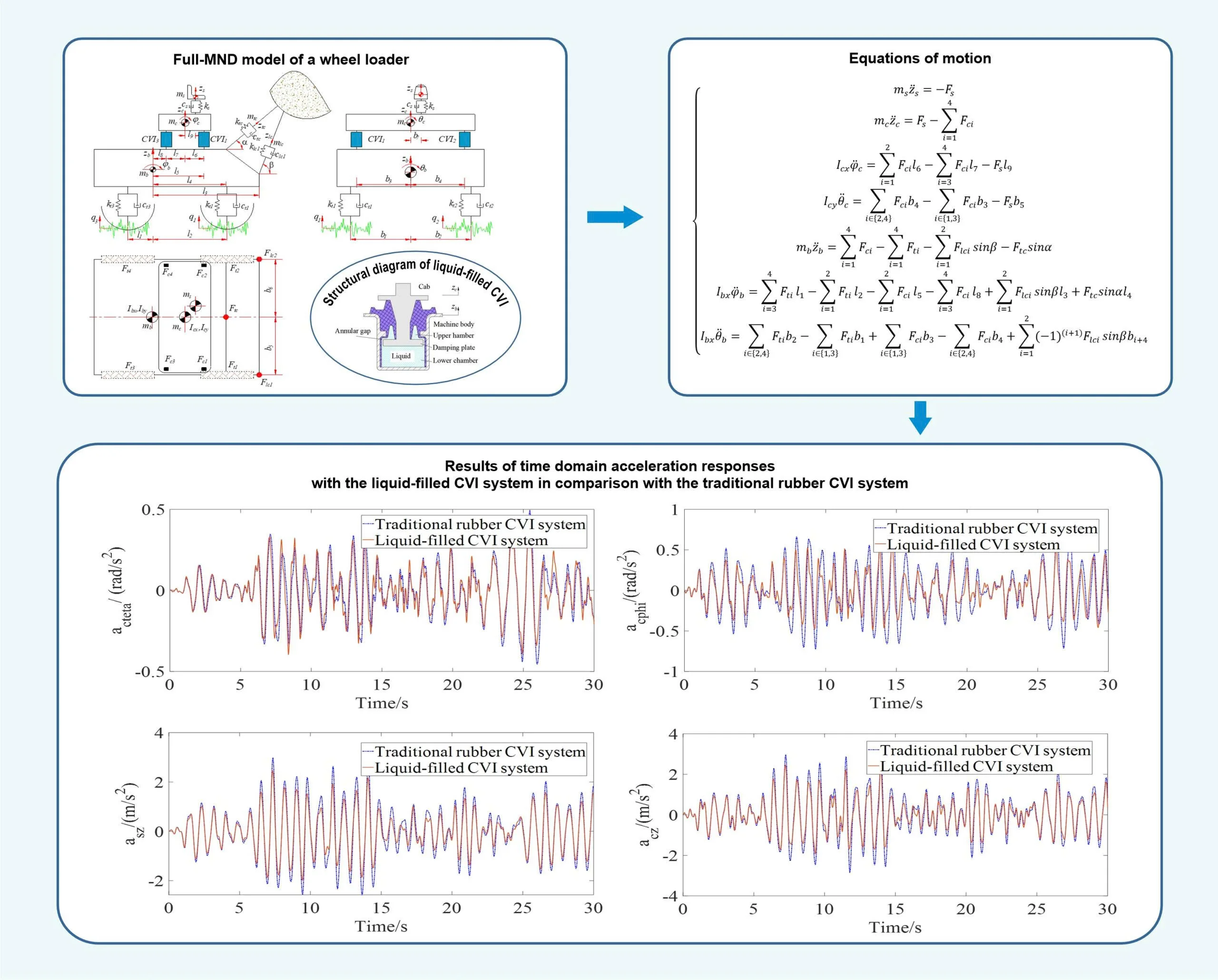
2. Full-MND model of wheel loader
2.1. Determining the nonlinear force of a liquid-filled CVI
The nonlinear dynamic model of the liquid-filled cab vibration isolation (CVI) system equipped with an annular orifice is developed to characterize its vertical nonlinear force response. The structural configuration of the liquid-filled CVI is shown in Fig. 1(a), and its corresponding nonlinear dynamic model is presented in Fig. 1(b). The model incorporates the machine and cab masses ( and ), the rubber stiffness and damping coefficients ( and ), the vertical displacements of the machine body and cab ( and ), the vertical reaction forces generated by the liquid-filled CVI () and and the fluid pressures in chambers 1 and 2 ( and ), where 1 to 4.
Based on Fig. 1(b), the vertical force of liquid-filled CVI can be expressed as:
where, denotes the vertical force of the rubber CVI which is defined by the following Eq. (2) and denotes the nonlinear damping force of hydraulic CVI which is generated by the liquid portion, and it is defined by Eq. (3):
where represents the pressure drop across the annular gap, represents the effective pressure-receiving area of the damping plate responsible for generating vertical hydraulic force.
Based on the conservation of mass, the relationship between the mean flow velocity in the annular gap and the piston’s vertical velocity is given by:
where represents the effective flow area of the upper fluid chamber connected to the damping plate motion; is the flow area of the annular passage; denotes the average axial flow velocity through the gap; is the relative vertical velocity of the piston.
Fig. 1Nonlinear dynamical model of liquid-filled CVI systems
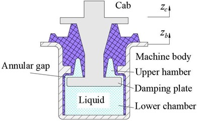
a) Structural diagram
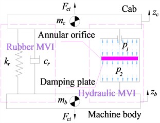
b) Nonlinear dynamical model
The pressure drop across the annular gap, caused by turbulent or transitional flow, follows a nonlinear quadratic dependence on the flow velocity ([3], [5]) and is expressed as:
where is the fluid density; is the flow resistance coefficient corresponding to the annular gap regions of the oil system.
By substituting Eqs. (4) and (5) into Eq. (3), the nonlinear damping force of the hydraulic CVI can be expressed as:
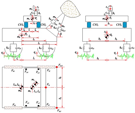
2.2. Full -MND model
To analyze the ride comfort performance of a wheel loader equipped with the liquid-filled cab CVI systems () compared to the traditional rubber CVI systems () under large-amplitude and low-frequency excitations, a full-machine nonlinear dynamic model is developedased on the reference presented in [17], as illustrated in Fig. 2. As illustrated in Fig. 2, the masses of the driver, cab, and machine body are denoted by , and , respectively. The vertical displacements at the centers of mass of the driver seat, cab, and machine by are represented by , and , respectively. The pitch and roll angles of the cab and machine body are denoted by , and , , respectively. The driver seat suspension system is characterized by a stiffness coefficient and damping coefficient . The stiffness and damping properties of the tires are defined by and . The stiffness and damping coefficients of the bucket tilting cylinders are defined by and , respectively. The stiffness and damping coefficients of the right and left bucket lifting cylinders are defined by and as well as and , respectively. The moment of inertia of the cab and machine body about the longitudinal lateral axises are defined by , and , , respectively. The displacements along the loader arm axis and piston axis are described by and , with corresponding equivalent masses and . The ground excitation input is denoted by . The distances are defined by an , where 1 to 9, 1 to 7. The vertical forces of the tires, cab’s CVI systems, driver’s seat suspension system, and the bucket control cylinders are denoted by , , , , and , respectively. The angles between the axes of the boom and bucket cylinders and the horizontal planeare denoted by and , respectively.
As illustrated in Fig. 2, the equations of motion governing the mechanical system are formulated based on Jourdain’s principle [23] and the classical Newton-Euler approach.
In parallel, the dynamic motion of the supporting mechanical body including machine body, cab and driver seat is governed by Eq. (7):
The dynamic response of the bucket assembly under operating conditions is described by Eq. (8):
2.3. Off-highway road surface excitation
To evaluate off-road ride dynamics realistically, terrain-induced excitations are modeled as filtered Gaussian white noise, capturing the stochastic nature of unstructured ground. The vertical input is generated via a first order shaping filter in the time domain:
where is the road elevation input, is the spatial cutoff frequency (Hz); is the reference spatial frequency (commonly 0.1 m-1), represents the road roughness spectral density at , is the forward velocity of the vehicle (m/s), and is a zero-mean unit variance Gaussian white noise process.
Fig. 2Full-MND model of a wheel loader
In accordance with ISO 8608 [16], surface roughness is classified by the spectral density where higher values correspond to rougher terrain. For off-highway applications, classes D to H are typically selected to represent severe working conditions in construction and mining, ensuring that the excitation input realistically reflects the statistical nature of irregular ground surfaces.
3. Ride comfort assessment for off-highway construction machinery
Ride comfort in off-highway construction vehicles is primarily affected by whole-body vibration (WBV) transmitted through the cab vibration isolation (CVI) systems, and seat suspension system during operation on rough terrain. Excessive WBV not only degrades operator comfort but also increases fatigue and long-term health risks. Ride comfort is evaluated using the frequency-weighted r.m.s. acceleration specified in ISO 2631-1 [18-22] and formulated in Eq. (10):
where is the time-varying weighted acceleration (m/s²); is is the measurement duration (s).
4. Results and discussion
The dynamic model described in Section 2 is implemented in MATLAB/Simulink to evaluate and compare the ride comfort performance of the liquid-filled CVI and traditional rubber CVI systems under large-amplitude, low-frequency excitations. The time-domain vertical accelerations at the driver’s seat and the cab floor center of gravity ( and ), as well as the time-domain angular accelerations of the cab’s pitch and roll motions ( and ) with the liquid-filled CVI systems in the rubber CVI systems are shown in Fig.3 when the machine operates on ISO class E road surface (poor road surface condition with large-amplitude and low-frequency excitations) at 5 km/h and full load. The results presented in Fig. 3 demonstrate that the maximum amplitude values of , , and are significantly reduced when using the liquid-filled CVI system, in comparison with the traditional rubber CVI system. This indicates that the liquid-filled CVI provides substantial improvement in ride comfort performance for wheel loaders under severe excitation conditions.
According to the results in Fig. 3, the root mean square (RMS) accelerations , , and are computed by Eq. (10) based on ISO 2631 (1997) [18]. The comparative values of these accelerations between the liquid-filled and rubber CVI systems are listed in Table 1. The RMS acceleration values of , , and with the liquid-filled CVI system are reduced by 31.12 %, 24.76 %, 15.00 %, and 11.59 %, respectively, compared to the traditional rubber CVI system under the investigated operating conditions. These results confirm that the liquid-filled CVI system outperforms its rubber-based counterpart in attenuating cab vibration responses, thereby contributing to improved ride quality under large-amplitude, low-frequency excitations on rough ground surfaces.
Fig. 3Results of time domain acceleration responses with the liquid-filled CVI system in comparison with the traditional rubber CVI system
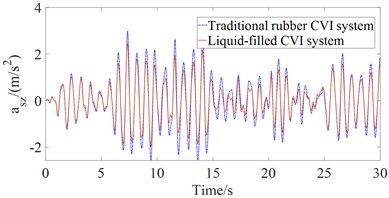
a) Driver’s seat
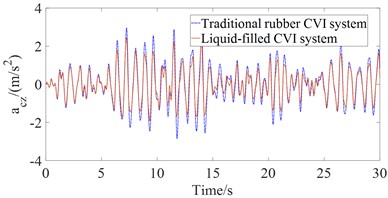
b) Cab body
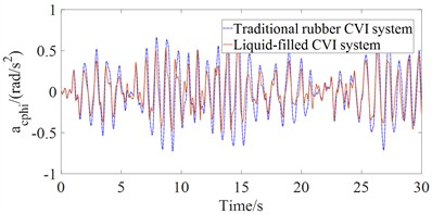
c) Pitching angle of cab
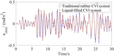
d) Rolling angle of cab
Table 1awsz, awcz, awcphi and awcteta values
/ (m/s2) | / (m/s2) | / (rad/s2) | / (rad/s2) | |
Traditional rubber CVI system | 1.0327 | 1.0216 | 0.3094 | 0.1539 |
Liquid-filled CVI system | 0.7986 | 0.7916 | 0.2102 | 0.1393 |
Decrease % | 22.67 | 22.51 | 32.06 | 9.49 |
5. Conclusions
In this study, a nonlinear full-vehicle dynamic model integrated with a liquid-filled cab vibration isolation (CVI) system was developed to evaluate ride comfort in comparison with a traditional rubber CVI system under large-amplitude, low-frequency excitation. The simulation results revealed that the maximum amplitude values of , , and were significantly reduced when employing the liquid-filled CVI system. Furthermore , , and values decreased by 31.12 %, 24.76 %, 15.00 %, and 11.59 %, respectively, compared to those obtained with the traditional rubber CVI under the investigated operating conditions. These quantitative improvements demonstrate that the liquid-filled CVI system offers superior vibration attenuation characteristics compared to the rubber-based configuration, thereby contributing to enhanced ride quality and improved operational stability of wheel loaders under harsh low-frequency excitations.
References
-
V. Nguyen, J. Zhang, V. Le, and R. Jiao, “Vibration analysis and modeling of an off‐road vibratory roller equipped with three different cab’s isolation mounts,” Shock and Vibration, Vol. 2018, No. 1, pp. 1–17, May 2018, https://doi.org/10.1155/2018/8527574
-
R. Jiao, V. Nguyen, and V. Le, “Ride comfort performance of hydro pneumatic isolation for soil compactors cab in low frequency region,” Journal of Vibroengineering, Vol. 22, No. 5, pp. 1174–1186, Aug. 2020, https://doi.org/10.21595/jve.2020.21345
-
C. C. Huan, D. V. Ha, L. A. Vu, T. Thoan, and L. Quynh, “Ride comfort evaluation for a wheel loader with cab’s hydraulic isolation system,” Lecture Notes in Networks and Systems, Vol. 602, pp. 846–854, Dec. 2022, https://doi.org/10.1007/978-3-031-22200-9_89
-
L. van Quynh, L. A. Vu, B. van Cuong, H. A. Tan, and L. X. Long, “A comparative analysis of ride performance of double-drum vibratory roller with two cab mount systems,” in Lecture Notes in Networks and Systems, Vol. 366, pp. 19–30, Jan. 2022, https://doi.org/10.1007/978-3-030-92574-1_3
-
T. Li, “Analysis and optimization of the quadratic damping values of hydraulic dampers added in vibratory roller’s cab isolations,” The International Journal of Acoustics and Vibration, Vol. 30, No. 1, pp. 102–111, Mar. 2025, https://doi.org/10.20855/ijav.2025.30.12116
-
B. van Cuong, C. C. Huan, L. van Quynh, and D. T. Binh, “Effects of design parameters of cab’s suspension system on an agricultural tractor ride comfort,” in Lecture Notes in Networks and Systems, Vol. 602, pp. 881–886, Dec. 2022, https://doi.org/10.1007/978-3-031-22200-9_93
-
Le van Quynh and Thao V. T. P., “Study on influence of design parameters of drum’s metal rubber isolation system of double vibratory roller on ride comfort,” International Research Journal of Engineering and Technology (IRJET), Vol. 6, No. 6, pp. 1647–1651, Jun. 2019.
-
L. Quynh, J. R. Zhang, G. W. Jiao, X. B. Liu, and Y. Wang, “Vibration analysis and optimal design for cab’s isolation system of vibratory roller,” Advanced Materials Research, Vol. 199-200, pp. 936–940, Feb. 2011, https://doi.org/10.4028/www.scientific.net/amr.199-200.936
-
L. Quynh, Z. Jianrun, N. Liem, B. Cuong, L. X. Long, and D. T. Phuong, “Experimental modal analysis and optimal design of cab’s isolation system for a single drum vibratory roller,” Vibroengineering Procedia, Vol. 31, pp. 52–56, May 2020, https://doi.org/10.21595/vp.2020.21325
-
L. van Quynh, N. T. Duy, N. van Liem, B. van Cuong, and L. X. Long, “Optimal design of cab’s isolation system for a single-drum vibratory roller,” in Lecture Notes in Networks and Systems, pp. 619–627, Nov. 2020, https://doi.org/10.1007/978-3-030-64719-3_68
-
N. T. Duy, L. van Quynh, D. V. Ha, B. van Cuong, and L. X. Long, “Ride comfort evaluation for a double-drum vibratory roller with semi-active hydraulic cab mount system,” in E3S Web of Conferences, Vol. 304, p. 01008, Sep. 2021, https://doi.org/10.1051/e3sconf/202130401008
-
L. van Quynh, D. V. Ha, B. van Cuong, L. A. Vu, and T. van Thoan, “Improvement of ride comfort quality for an earth-moving machinery with semi-active cab isolation system,” in E3S Web of Conferences, Vol. 304, p. 02012, Dec. 2021, https://doi.org/10.1051/e3sconf/202130402012
-
V. Quynh, “Ride comfort evaluation of vibratory roller under different soil ground,” Transactions of the Chinese Society of Agricultural Engineering, Vol. 29, No. 9, pp. 39–47, Sep. 2013.
-
Y. Wang, Y. Lu, J. Wang, and J. Liu, “Study nonlinear vibration characteristics of vibrating roller-subgrade coupled system in the initial and middle stages of vibratory compaction,” Journal of Low Frequency Noise, Vibration and Active Control, Vol. 44, No. 1, pp. 159–177, Sep. 2024, https://doi.org/10.1177/14613484241281234
-
Q. Le and K. T. Nguyen, “Optimal design parameters of cab’s isolation system for vibratory roller using a multi-objective genetic algorithm,” Applied Mechanics and Materials, Vol. 875, pp. 105–112, Jan. 2018, https://doi.org/10.4028/www.scientific.net/amm.875.105
-
“Mechanical vibration. Road surface profiles. Reporting of measured data,” BSI British Standards, London, ISO 8068, Feb. 2024.
-
W. Tao et al., “Design of suspension damping for wheel loader cab based on fuzzy control,” (in Chinese), Journal of Highway and Transportation Research and Development, Vol. 37, No. 11, pp. 118–122, Nov. 2020, https://doi.org/10.3969/j.issn.1002-0268.2020.11.015
-
“Mechanical vibration and shock-evaluation of human exposure to whole body vibration-part 1: general requirements,” ISO 2631-1, 1997.
-
L. X. Long, L. Quynh, and B. Cuong, “Study on the influence of bus suspension parameters on ride comfort,” Vibroengineering Procedia, Vol. 21, pp. 77–82, Dec. 2018, https://doi.org/10.21595/vp.2018.20271
-
N. T. Dung, B. Cuong, L. Quynh, N. Dung, and V. T. Hoang, “Evaluation of ride performance of PID controller in active suspension systems for an electric vehicle,” Vibroengineering Procedia, Vol. 57, pp. 175–181, Dec. 2024, https://doi.org/10.21595/vp.2024.24545
-
D. V. Ha, L. van Quynh, and L. X. Long, “Performance analysis of a mining dump truck ride comfort with a hydro-pneumatic suspension system under different operating conditions,” in Lecture Notes in Networks and Systems, pp. 790–797, Dec. 2022, https://doi.org/10.1007/978-3-031-22200-9_83
-
N. V. Liem et al., “Study of fuzzy control for cab’s isolation system of heavy truck,” Vibroengineering PROCEDIA, Vol. 10, pp. 309–314, 2016.
-
V. L. Nguyen, V. Q. Le, and R. Jiao, “A modified technique for studying the automotive vibrations based on Jourdain’s principle,” Vibroengineering PROCEDIA, Vol. 22, pp. 99–105, Mar. 2019, https://doi.org/10.21595/vp.2018.20458
About this article

The work was supported by Thai Nguyen University of Technology.
The datasets generated during and/or analyzed during the current study are available from the corresponding author on reasonable request.
The authors declare that they have no conflict of interest.
