Abstract
With the continuous increase in the operating mileage of China’s high-speed railway network, wheel out-of-roundness has become increasingly common in electric multiple unit (EMU) vehicles. Wheel out-of-roundness directly increases the vibration level of the axle, affects various vehicle components, and in severe cases, may lead to fatigue fracture of the axle – a key load-bearing component – thereby causing major safety incidents. To investigate the influence of wheel out-of-roundness on axle dynamic stress and to evaluate the fatigue strength of the axle under such conditions, this study analyzes the effects of different wheel flat lengths, polygon orders and depths, as well as various operating speeds on the dynamic stress of EMU axles. Based on numerical simulation results, the fatigue damage of the axle under wheel out-of-round conditions and the impact of wheel polygonal wear over one development cycle are calculated. The findings show that within a single re-profiling cycle, wheel flats shorter than 50 mm have a negligible effect on axle fatigue damage. Furthermore, a reference limit for polygonal wear depth is proposed, providing theoretical guidance for wheel maintenance and safety assessment of EMU vehicles.
1. Introduction
The technology of high-speed trains is advancing rapidly. At present, while maintaining safety and passenger comfort, efforts are being made to further increase both train speed and operating mileage. However, as the mileage of high-speed rail vehicles continues to grow, wheel wear has become increasingly severe, accompanied by various wheel defects – among which wheel out-of-roundness is one of the most common and significant forms of deterioration [1, 2]. Wheel out-of-roundness mainly includes several types such as wheel flats, local depressions, and polygonal wear. During high-speed operation, these defects can cause considerable harm to both the vehicle and the track system. They intensify the impact forces at the wheel–rail interface, leading to high-frequency vibrations in the wheel-rail system. Such vibrations can accelerate fatigue damage in bogie components, including axles [3]. In addition, the repeated high-frequency impacts between the wheel and rail increase operational noise, reduce ride comfort, and may even result in serious safety incidents [4, 5].
Among the different types of wheel out-of-roundness, wheel polygonal wear is particularly prevalent and hazardous. Once polygonal wear develops, it directly affects wheel-rail contact dynamics and transmits impact loads to the track and subgrade [5]. Meanwhile, the reactive forces from the track alter the wheel-rail contact forces, producing high-frequency vibrations that propagate through the wheelset to components such as the axle box and gearbox [6, 7, 8], thereby influencing their dynamic characteristics. With the continuous increase in high-speed rail operation, incidents such as the 1998 intercity express derailment caused by wheel polygonal wear [9] underscore the urgency of addressing polygonal wear issues in the railway industry.
In studying the formation mechanisms of wheel polygonal wear, numerous domestic and international scholars have suggested that its development is closely related to the resonance of the wheelset’s bending modes. Meywerk [10] proposed that polygon formation is associated with the first- and second-order bending modes of the wheelset, as simulations demonstrated that flexible deformation of the wheel-rail contact leads to micro-slippage, with the largest slip occurring within the resonance frequency range of these modes. Jin et al. [11] conducted experimental measurements of vibration modes in various vehicle components, showing that the passing frequency of polygonal wear closely matches the first-order bending frequency of the wheelset [12]. Morys [9] developed a vehicle-track dynamics model incorporating a wheel wear model to study the deterioration pattern of wheel wear, concluding that wear of a specific order intensifies wheel-rail impact forces. Yang et al. [13] built a three-dimensional heavy-haul train-track coupled dynamics model to analyze the dynamic interactions caused by polygonal wear, finding that highorder polygonal wear dominates locomotive-track vibration responses. Vehicle-track coupling models established by Liu [14] and Wu [15] also confirmed that the short-wavelength components induced by high-order polygonal wear excite high-frequency track vibrations. Similarly, a coupled vehicle-track-wear model developed by Luo et al. [16] showed that resonance bands induced by polygonal wear align closely with the first-order bending natural frequency of the wheelset.
Overall, these studies reveal a strong resonance relationship between wheel polygonal wear and wheelset dynamics. Meanwhile, both domestic and international researchers have explored related aspects such as wheel-axle resonance, P2-force resonance, and axle material properties. Song et al. [17] analyzed this issue using a vehicle-track coupled dynamic model that considered flexible wheelsets, finding that the vertical wheel-rail force increases with the amplitude of wheel polygonization, though not linearly with polygon order. When the polygonal frequency falls within the wheelset’s bending vibration frequency range, resonance occurs, amplifying the wheel-rail interaction forces. Wu et al. [18] proposed limit values for polygonization based on both axle strength and wheel-rail forces, while Song [17] also suggested polygonal limits derived from the maximum allowable wheel-rail force.
Despite extensive research, there remains no unified consensus on the underlying mechanisms driving the formation of wheel polygonal wear [12, 19, 20]. Currently, the primary mitigation strategy involves periodic wheel re-profiling operations [21]. Therefore, in the absence of a definitive understanding of polygonal formation mechanisms [22], it is of great significance to investigate the effects of wheel polygonal wear on axle dynamic behavior and fatigue performance.
2. Model establishment
2.1. Wheel flat model
Wheel flats can be categorized into new flats and old flats, and the models for these two types of wheel flats are different. This study adopts a wheel radius variation approach to describe the flat model. During one complete wheel rotation, the change in the wheel’s circumferential radius is defined as follows [23]:
where: is the variation in the wheel’s circumferential radius; is the depth of the flat; is the nominal rolling radius of the wheel. In this study, 0.43 m; is the length of the flat (in meters).
The new flat model is relatively idealized and does not frequently occur in practice. As the train operates at high speeds, new flats are typically worn down quickly, transforming into old flat models. Existing old flat models often use a cosine function to reflect the gradual change in flat depth, as follows [24]:
where: is the length of the flat (in meters).
Based on this, the wheel flat is transformed into a variation in wheel radius:
where: ; is the wheel rotation angle (in radians).
2.2. Wheel polygonization model
Wheel polygonization is generally composed of multiple harmonics with different frequencies, amplitudes, and phase angles. To describe wheel polygonization, it is often simplified as a combination of simple harmonic waves. Under ideal conditions, wheel polygonization can be expressed as:
where: is the variation in wheel radius; is the amplitude of the order polygonization; is the order of wheel polygonization (number of sides); is the wheel rotation angle (in radians); is the initial phase angle of the order polygonization; is the actual radius of the wheel; is the nominal rolling radius of the wheel; is the angular velocity of the wheel.
The wheel roughness level (in units of dBre1μm) is defined by the following formula:
where: is the mean square value of the wheel out-of-roundness roughness quantized within the th 1/3 octave band; is the reference value for wheel roughness.
Under international standard units, the center wavelength of the frequency band is given by:
Within each 1/3 octave band, the narrowband spectral amplitudes are squared, summed, and divided by the number of calculation points to obtain [25].
3. The impact of wheel out-of-roundness on axle dynamic stress
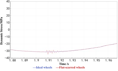
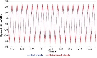
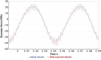
Since newly formed wheel flats quickly develop into mature flats during high-speed operation, this study focuses primarily on simulations using the old flat model. Both the old flat and polygonal wear models are incorporated into the vehicle–track dynamic model in functional form for numerical analysis. The simulation results indicate that, under wheel flat conditions, the axle dynamic stress exhibits small-amplitude fluctuations at the flat position, as illustrated in Fig. 1(a) and Fig. 1(b). In contrast, under wheel polygonal wear conditions, the axle dynamic stress shows small-amplitude cyclic variations around the peak values, as shown in Fig. 1(c) and Fig. 1(d).
Fig. 1Comparison of axle dynamic stress between wheel roundness defects and ideal wheel
a) Impact of flat spot on axle dynamic stress
b) Local amplification
c) Impact of polygonal wear on axle dynamic stress
d) Local amplification
From the stress curves shown in Fig. 1, it can be observed that the axle dynamic stress signal primarily consists of a fundamental harmonic component superimposed with high-frequency, small-amplitude cyclic waves. Under ideal wheel conditions, the magnitude of the axle stress (i.e., the fundamental stress) is mainly governed by the vertical loads transmitted from the car body and bogie, while its frequency is determined by the rotational frequency of the axle. However, the presence of wheel out-of-roundness introduces high-frequency cyclic fluctuations in the dynamic stress response. When the fundamental stress remains constant, the overall dynamic stress amplitude is mainly reflected by the magnitude of these high-frequency components induced by wheel defects.
The amplitude of the impact generated by a wheel flat is affected by parameters such as vehicle speed, flat depth, and flat length. In contrast, the high-frequency stress amplitude associated with wheel polygonal wear is primarily influenced by the polygon order, wave depth, and running speed. The following section presents simulation analyses of axle dynamic stress under various wheel out-of-roundness conditions to quantitatively assess these effects.
3.1. Impact of wheel flats on axle dynamic stress
To investigate the influence of flat length and vehicle speed on axle dynamic stress, the dynamic response was calculated for a single flat positioned identically on both wheels. The dynamic stress was extracted at a cross-section located 35 mm inward from the gearbox side of the axle seat, corresponding in phase with the wheel flat. Simulations were conducted for flat lengths of 10 mm, 20 mm, 30 mm, 40 mm, and 50 mm under various operating speeds, and the results are presented in Fig. 2. Under the same flat length condition, the axle dynamic stress was observed to increase initially and then decrease with increasing speed, reaching a maximum value of 101 MPa at approximately 50 km/h.
Fig. 2Effect of flat spot length on stress amplitude at different speeds
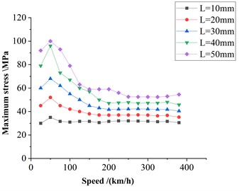
Fig. 3Effect of flat spot length on stress amplitude at the same speed
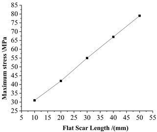
Fig. 4Axle dynamic stress spectrum at 50 km/h with a 50 mm flat spot length
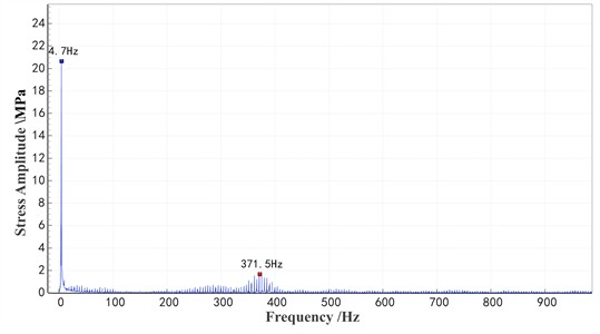
As shown in Fig. 3, which illustrates the relationship between axle stress and flat length at a speed of 100 km/h, the axle dynamic stress increases linearly with the length of the flat. Longer flats with greater depths result in higher axle dynamic stress. For a 50 mm flat, the dynamic stress data at 50 km/h is subjected to a Fast Fourier Transform (FFT), as shown in the frequency spectrum in Fig. 4. At 50 km/h, the wheel flat excites frequencies within the range of 350-400 Hz, which is close to the first-order bending frequency of the wheelset on one side.
3.2. Impact of wheel polygonization on axle dynamic stress
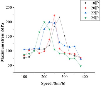
The influence of wheel polygonization on axle dynamic stress can be analyzed in terms of three key factors: polygon order, wave depth, and vehicle speed. Accordingly, simulations were performed to extract axle dynamic stress under polygonization conditions, wave depths, and speeds representative of typical high-speed train operations. As shown in Fig. 5 for a given polygon order, the maximum axle stress initially increases with speed and then decreases, reaching a peak within the simulated speed range. Fig. 6 illustrates the variation of maximum axle stress with different polygon orders and speeds at a fixed wave depth of 0.3 mm. It can be observed that higher polygon orders correspond to lower speeds at which the stress peaks occur.
The excitation frequency associated with polygonal wear can be calculated using the following formula:
where: is the excitation frequency of wheel polygonization (in Hz); is the vehicle speed (in km/h); is the polygon order; is the wheel diameter (0.92 m).
Using Eq. (9), the excitation frequencies corresponding to the maximum axle stress peaks for polygon orders of 18, 20, 22, and 25 are calculated as 475.73 Hz, 480.54 Hz, 475.73 Hz, and 480.54 Hz, respectively. These frequencies are close to the simulated fourth-order bending frequency of the wheelset at 490.11 Hz. Therefore, it is concluded that the increase in maximum axle stress may be due to the excitation of the fourth-order bending mode of the wheelset by wheel polygonization during operation. This excitation amplifies the dynamic forces on the wheelset, leading to a significant increase in axle stress.
Fig. 5Relationship between maximum stress and speed at different wave depths under 18th-order polygonal wear
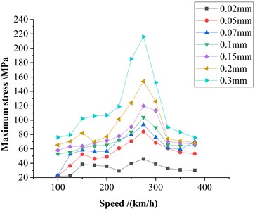
Fig. 6Relationship between maximum stress and speed at different orders of polygonal wear with a 0.3 mm wave depth
By comparing the maximum axle stress under the same speed and polygon order, as shown in Fig. 7, the relationship between maximum axle stress and polygon wave depth for an 18th-order polygon at speeds of 200 km/h and 250 km/h can be observed. It is evident that the maximum axle stress increases with wave depth, exhibiting an approximately linear growth trend.
Fig. 7Relationship between maximum axle stress and wave depth
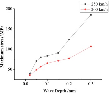
Fig. 8Relationship between maximum axle stress and polygonal order
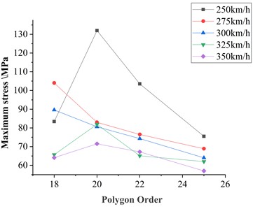
When comparing maximum axle stress under the same speed but with different polygon orders at a fixed wave depth, as shown in Fig. 8, the stress response for polygon orders ranging from 18 to 25 at speeds between 250 and 350 km/h and a wave depth of 0.1 mm was analyzed. The results indicate that the maximum axle stress does not follow a clear trend with increasing polygon order.
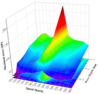
Overall, axle dynamic stress is strongly influenced by both polygon wave depth and vehicle speed. As illustrated in Fig. 9, which shows the relationship between speed, wave depth, and maximum axle stress for a 20th-order polygon, the effect of wave depth on the axle is direct and pronounced, with stress increasing as wave depth grows. In contrast, the influence of speed is closely related to the modal characteristics of the wheelset. Consequently, the speed at which maximum axle stress occurs corresponds to the excitation frequency of the wheelset’s modal response. Notably, higher polygon orders require lower speeds to excite the corresponding wheelset modal frequencies.
Fig. 9Relationship between maximum axle stress, speed, and wave depth
4. Evaluation of damage to the axle due to non-round wheels
4.1. Fatigue damage assessment of axle under wheel flat conditions
As noted previously, wheel flats have the greatest impact on axle dynamic stress at speeds around 50 km/h. However, in actual vehicle operation, the proportion of time spent traveling near this speed is relatively small. To better reflect real-world conditions, the fatigue strength assessment of the axle under wheel flat conditions is therefore conducted at a more representative speed of 300 km/h, which corresponds to the predominant operating range of high-speed trains.
The dynamic model was used to simulate the aforementioned conditions, and the corresponding stress-time history data were extracted. The simulated stress data were then processed using the rainflow counting method to obtain the stress spectrum. The number of cycles from the simulation was extended to cover a full wheel re-profiling period, and the axle fatigue damage was calculated based on standard fatigue strength assessment methods. The cumulative fatigue damage and equivalent stress amplitude for different flat lengths are summarized in Table 1.
Table 1Fatigue damage calculation results of axle under flat spot conditions
Length of flat scar /mm | Damage value within one grinding cycle | Equivalent stress /MPa |
10 | 9.07×10⁻⁵ | 22.54 |
20 | 1.88×10⁻⁴ | 26.08 |
30 | 3.80×10⁻⁴ | 30.02 |
40 | 7.54×10⁻⁴ | 34.42 |
50 | 1.41×10⁻⁴ | 39.00 |
As shown in Table 1, within a single re-profiling cycle (i.e., 300,000 km), fatigue damage to the axle caused by wheel flats increases with flat length. However, the overall damage remains very small and is insufficient to cause fatigue failure. Considering that high-speed trains operate with an average annual mileage of 600,000 km and have a design service life of 20 years, the total design mileage is approximately 12 million km. If a 50 mm flat were to persist throughout this period, the cumulative fatigue damage to the axle would reach only 0.0564, still well below 1. According to the Operation and Maintenance Regulations for Railway High-Speed Trains, which set a maximum allowable flat length of 20mm, the fatigue damage caused by wheel flats under normal operating conditions is therefore negligible.
4.2. Fatigue damage assessment of axles under polygonal wheel conditions
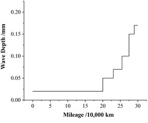
Since the characteristics of wheel polygonization change continuously in practice, it is challenging to accurately calculate the fatigue damage caused by polygonization over an entire re-profiling cycle. Therefore, equivalent simplifications are commonly applied in such calculations [15, 26]. Although the detailed development patterns of polygon orders remain poorly understood [19, 27], the dominant polygon orders are relatively well established: at a speed of 300 km/h, the dominant orders are 18th to 20th; at 250 km/h, the dominant orders are 23rd and 24th [28]. As illustrated in Fig. 10, which shows the evolution of wave depth for a 3rd-order polygon, previous research [29] indicates that wave depth growth exhibits abrupt changes, with the point of sudden change in wear rate referred to as the “transition mileage.” The smaller the initial polygon order and wave depth, the longer the transition mileage.
Based on statistical analyses of out-of-roundness measurements conducted on tens of thousands of wheels across multiple high-speed rail lines and train models, it was found that only 0.14 % of wheels had radial runout exceeding 0.3 mm, while the vast majority exhibited radial runout between 0 and 0.2 mm [1].
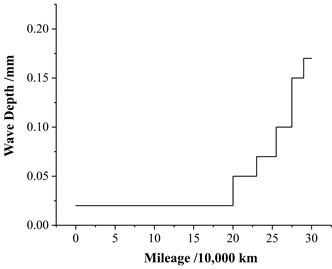
Therefore, in calculating the axle fatigue strength, two representative operating speeds are considered: 250 km/h and 300 km/h, corresponding to polygon orders of 24th and 20th, respectively. Due to the uncertainty in polygon order development, changes in polygon order are not considered, and the initial orders are assumed constant throughout the cycle. The initial wave depth is set to 0.02 mm, the maximum wave depth to 0.17 mm, and the transition mileage to 200,000 km. The specific calculation procedure is illustrated in Fig. 11.
Fig. 10Evolution trend of polygonal wave depth
Fig. 11Variation of wave depth with operating mileage
The evolution of wave depth over a single re-profiling cycle is calculated based on Fig. 11. Corresponding dynamic stress data for various wave depths are obtained through simulation, and the fatigue damage is evaluated following the same procedure described in the previous section. The calculated fatigue damage results for the axle under 24th-order polygon conditions within one re-profiling cycle are presented in Table 2, while the results for the 20th-order polygon conditions are summarized in Table 3.
The calculation results indicate that within a single re-profiling cycle, the cumulative fatigue damage to the axle under 24th-order polygon conditions is 9.78×10⁻³, while under 20th-order polygon conditions, the cumulative fatigue damage is slightly higher at 1.17×10⁻². Overall, the damage caused by wheel polygonization remains relatively minor, and the corresponding equivalent stress amplitudes are well below the allowable strength limits. Therefore, it can be concluded that wheel polygonization within one re-profiling cycle induces only limited fatigue damage, insufficient to cause axle fatigue failure. However, compared with the condition of an ideal wheel, both 24th- and 20th-order polygons result in significantly greater fatigue damage to the axle.
Table 2Fatigue damage calculation results of axle under 24th-order polygonal wear conditions
Wave depth /mm | Fatigue damage | Equivalent stress / MPa | Average damage per 104 km |
Ideal Wheel | 7.71×10⁻⁵ | 21.81 | 3.86×10⁻⁶ |
0.02 | 2.15×10⁻³ | 42.46 | 1.08×10⁻⁴ |
0.05 | 6.15×10⁻⁴ | 33.05 | 2.05×10⁻⁴ |
0.07 | 1.96×10⁻³ | 41.68 | 7.84×10⁻⁴ |
0.10 | 1.57×10⁻³ | 39.87 | 7.85×10⁻⁴ |
0.15 | 1.71×10⁻³ | 40.57 | 1.14×10⁻³ |
0.17 | 1.77×10⁻³ | 40.81 | 1.77×10⁻³ |
Total damage | 9.78×10⁻³ | – | – |
Table 3Fatigue damage calculation results of axle under 20th-order polygonal wear conditions
Wave depth /mm | Fatigue damage | Equivalent stress / MPa | Average damage per 104 km |
Ideal Wheel | 7.71×10⁻⁵ | 21.81 | 3.86×10⁻⁶ |
0.02 | 8.06×10⁻⁴ | 34.88 | 4.03×10⁻⁵ |
0.05 | 1.23×10⁻³ | 37.94 | 4.10×10⁻⁴ |
0.07 | 1.62×10⁻³ | 40.14 | 6.48×10⁻⁴ |
0.10 | 2.23×10⁻³ | 42.77 | 1.12×10⁻³ |
0.15 | 2.79×10⁻³ | 44.75 | 1.86×10⁻³ |
0.17 | 3.01×10⁻³ | 45.40 | 3.01×10⁻³ |
Total damage | 1.17×10⁻² | – | – |
Based on the wave depth evolution pattern illustrated in Fig. 11, if each re-profiling cycle follows the same development process, the cumulative fatigue damage to the axle after 40 re-profiling cycles would reach approximately 0.39 for 24th-order polygons and 0.468 for 20th-order polygons. Both values remain below the critical fatigue threshold of 1, indicating that the axle will not experience fatigue failure throughout its service life.
Furthermore, analysis of the fatigue damage per unit mileage reveals that, for both 24th- and 20th-order polygons, the damage per unit distance increases as the polygon wave depth increases. Examination of the damage values across different stages of the 20th-order polygon shows that although the mileage corresponding to larger wave depths is shorter, the total fatigue damage accumulated in these stages is considerably higher.
In summary, greater polygon wave depths lead to increased fatigue damage in the axle. Therefore, when significant polygonal wear is detected, timely wheel re-profiling should be performed to mitigate further damage and ensure operational safety.
5. Conclusions
Considering the increasing operating mileage of high-speed trains and the urgent need to address the frequent occurrence of wheel out-of-roundness in EMU vehicles, this study establishes wheel flat and wheel polygonal wear models. Using a rigid–flexible coupled dynamic model, the dynamic stress of the axle is calculated to analyze how wheel out-of-roundness affects axle dynamic stress. Through simulation under different wheel flat and polygonal conditions, the relationships between axle dynamic stress and factors such as wheel flat length, polygon order, polygonal depth, and operating speed are investigated. The results show that axle dynamic stress is significantly affected by wheel flat length and polygonal depth, while the influence of polygon order is not obvious. The effect of speed is mainly related to the wheelset’s modal characteristics.
Subsequently, the fatigue damage of the axle caused by wheel flats and wheel polygonization within a single re-profiling (re-turning) cycle is calculated. The results indicate that when the wheel flat length is less than 50 mm, the cumulative damage value is only 1.41×10⁻³, and the total value over the entire design life is 0.0564, implying that the axle will not undergo fatigue fracture and its service life will not be affected. The influence of wheel polygonization on axle fatigue damage within a single re-profiling cycle is relatively small. Analysis of fatigue damage per unit mileage under different polygonal depths shows that axle fatigue damage caused by polygonal wear is strongly affected by the polygonal depth. When the depth becomes large, timely re-profiling is necessary. Finally, the calculated polygonal wear limit for axle fatigue provides useful guidance for practical train operation. However, this study considers only single-order polygonal wear when analyzing its effect on axle dynamic stress, while in actual operation, wheel polygonization often involves multiple orders coexisting. Future research can therefore focus on the influence of multi-order, complex polygonal wear on axle dynamic stress.
References
-
P. Wang, G. Tao, X. Yang, C. Xie, W. Li, and Z. Wen, “Analysis of polygonal wear characteristics of Chinese high-speed train wheels,” Journal of Southwest Jiaotong University, Vol. 58, No. 6, pp. 1357–1365, 2023, https://doi.org/10.3969/j.issn.0258-2724.20210777
-
W. Wang et al., “Initiation and evolution of wheel polygonal wear: Influence of wheel-rail hardness ratios,” Wear, Vol. 540-541, p. 205255, Mar. 2024, https://doi.org/10.1016/j.wear.2024.205255
-
J. Zeng, X. Peng, Q. Wang, H. Zhang, and S. Liang, “Review on detection technologies of railway vehicle wheel flat fault,” Journal of Traffic and Transportation Engineering, Vol. 22, No. 2, 2022, https://doi.org/10.19818/j.cnki.1671-1637.2022.02.001
-
V. V. Krishna, S. Hossein-Nia, C. Casanueva, S. Stichel, G. Trummer, and K. Six, “Rail RCF damage quantification and comparison for different damage models,” Railway Engineering Science, Vol. 30, No. 1, pp. 23–40, Sep. 2021, https://doi.org/10.1007/s40534-021-00253-y
-
N. Bosso, M. Magelli, and N. Zampieri, “Simulation of wheel and rail profile wear: a review of numerical models,” Railway Engineering Science, Vol. 30, No. 4, pp. 403–436, Aug. 2022, https://doi.org/10.1007/s40534-022-00279-w
-
Y. Hou et al., “Measured load spectra of the bearing in high-speed train gearbox under different gear meshing conditions,” Railway Engineering Science, Vol. 31, No. 1, pp. 37–51, Sep. 2022, https://doi.org/10.1007/s40534-022-00282-1
-
A. Mazzù, L. Solazzi, M. Lancini, C. Petrogalli, A. Ghidini, and M. Faccoli, “An experimental procedure for surface damage assessment in railway wheel and rail steels,” Wear, Vol. 342-343, pp. 22–32, Nov. 2015, https://doi.org/10.1016/j.wear.2015.08.006
-
L. Jing and K. Liu, “Review on wheel-rail dynamic responses caused by wheel tread defects,” Journal of Traffic and Transportation Engineering, Vol. 21, No. 1, p. 285, 2021, https://doi.org/10.19818/j.cnki.1671-1637.2021.01.014
-
B. Morys, “Enlargement of out-of-round wheel profiles on high speed trains,” Journal of Sound and Vibration, Vol. 227, No. 5, pp. 965–978, Nov. 1999, https://doi.org/10.1006/jsvi.1999.2055
-
M. Meywerk, “Polygonalization of railway wheels,” Archive of Applied Mechanics (Ingenieur Archiv), Vol. 69, No. 2, pp. 105–120, Mar. 1999, https://doi.org/10.1007/s004190050208
-
X. Jin, L. Wu, J. Fang, S. Zhong, and L. Ling, “An investigation into the mechanism of the polygonal wear of metro train wheels and its effect on the dynamic behaviour of a wheel/rail system,” Vehicle System Dynamics, Vol. 50, No. 12, pp. 1817–1834, Dec. 2012, https://doi.org/10.1080/00423114.2012.695022
-
S. Iwnicki, J. C. O. Nielsen, and G. Tao, “Out-of-round railway wheels and polygonisation,” Vehicle System Dynamics, Vol. 61, No. 7, pp. 1787–1830, Jul. 2023, https://doi.org/10.1080/00423114.2023.2194544
-
Y. Yang, L. Ling, C. Wang, Z. Liu, K. Wang, and W. Zhai, “Wheel/rail dynamic interaction induced by polygonal wear of locomotive wheels,” Vehicle System Dynamics, Vol. 60, No. 1, pp. 211–235, Jan. 2022, https://doi.org/10.1080/00423114.2020.1807572
-
X. Liu and W. Zhai, “Analysis of vertical dynamic wheel/rail interaction caused by polygonal wheels on high-speed trains,” Wear, Vol. 314, No. 1-2, pp. 282–290, Jun. 2014, https://doi.org/10.1016/j.wear.2013.11.048
-
X. Wu, M. Chi, and P. Wu, “Influence of polygonal wear of railway wheels on the wheel set axle stress,” Vehicle System Dynamics, Vol. 53, No. 11, pp. 1535–1554, Nov. 2015, https://doi.org/10.1080/00423114.2015.1063674
-
R. Luo, J. Zeng, P. Wu, and H. Dai, “Simulation and analysis of wheel out-of-roundness wear of high-speed train,” Journal of the China Railway Society, Vol. 32, No. 5, pp. 30–35, 2010.
-
Z. Song, R. H. Yue, Xiaoyi, and X. Li, “Influence of wheel polygon on vehicle vibration and wheel/rail force,” Journal of Beijing Jiaotong University, Vol. 41, No. 6, p. 88, 2017, https://doi.org/10.11860/j.issn.1673-0291.2017.06.014
-
W. Yue, H. Jian, Z. Qiyu, J. Xuesong, X. Xinbiao, and L. Shulin, “Effect of rail corrugation on initiation and development of polygonal wear on high-speed train wheels,” Journal of Mechanical Engineering, Vol. 56, No. 17, p. 198, Jan. 2020, https://doi.org/10.3901/jme.2020.17.198
-
A. Ekberg and E. Kabo, “Fatigue of railway wheels and rails under rolling contact and thermal loading-an overview,” Wear, Vol. 258, No. 7-8, pp. 1288–1300, Mar. 2005, https://doi.org/10.1016/j.wear.2004.03.039
-
S. Qu, B. Zhu, J. Zeng, H. Dai, and P. Wu, “Experimental investigation for wheel polygonisation of high-speed trains,” Vehicle System Dynamics, Vol. 59, No. 10, pp. 1573–1586, Oct. 2021, https://doi.org/10.1080/00423114.2020.1772984
-
H. Zhu, H. Hu, B. Yin, P. Wu, J. Zeng, and Q. Xiao, “Research progress on wheel polygons of rail vehicles,” Journal of Traffic and Transportation Engineering, Vol. 20, No. 1, p. 102, 2020, https://doi.org/10.19818/j.cnki.1671- 1637.2020.01.008
-
Y. Yang, T. Wu, F. Lin, Q. Huang, H. Pang, and L. Zou, “Effect of comprehensive wheel-rail wear on dynamic performance of high-speed trains,” Mechanical Science and Technology for Aerospace Engineering, Vol. 42, No. 1, p. 1542, 2023, https://doi.org/10.13433/j.cnki.1003-8728.20220090
-
H. Zha, Z. Ren, and N. Xu, “Impact characteristics of axle box bearing due to wheel flat scars,” Journal of Traffic and Transportation Engineering, Vol. 20, No. 4, pp. 165–173, 2020, https://doi.org/10.19818/j.cnki.1671-1637.2020.04.013
-
G. Yang, Z. Ren, and Y. Yuan, “Influence of wheel flat on dynamic performance of high-speed train wheelset,” Journal of Beijing Jiaotong University, Vol. 42, No. 3, p. 103, 2018, https://doi.org/10.11860/j.issn.1673-0291.2018.03.014
-
R. Zhang, M. Chen, J. Han, and Y. Chen, “Analysis and study about abnormal abrasion of wheel tread in Shenhua electric locomotive,” Energy Science and Technology, Vol. 16, No. 11, pp. 78–87, 2018.
-
A. Ekberg, E. Kabo, and R. Lundén, “Rail and wheel health management,” Wear, Vol. 526-527, p. 204891, Aug. 2023, https://doi.org/10.1016/j.wear.2023.204891
-
Z. Wang et al., “Effects of polygonal wear of wheels on the dynamic performance of the gearbox housing of a high-speed train,” Proceedings of the Institution of Mechanical Engineers, Part F: Journal of Rail and Rapid Transit, Vol. 232, No. 6, pp. 1852–1863, Jan. 2018, https://doi.org/10.1177/0954409717752998
-
Y. Wu, X. Du, H.-J. Zhang, Z.-F. Wen, and X.-S. Jin, “Experimental analysis of the mechanism of high-order polygonal wear of wheels of a high-speed train,” Journal of Zhejiang University-SCIENCE A, Vol. 18, No. 8, pp. 579–592, Aug. 2017, https://doi.org/10.1631/jzus.a1600741
-
J. Ding, J. Yang, J. Hu, and F. Li, “Evolution of the polygonal wear of high-speed train wheels,” Journal of Mechanical Engineering, Vol. 56, No. 22, p. 184, Jan. 2020, https://doi.org/10.3901/jme.2020.22.184
About this article

This work was supported by the National Natural Science Foundation of China (Grant No. U2268211) and Natural Basic Science Center of China (Grant No. 52388102). We also thank our other colleagues for their valuable comments and suggestions that helped to improve the manuscript.
The datasets used during the current study are available from the corresponding author upon reasonable request.
Yonglin Men was writing the main manuscript text. Hao Hu was reviewing and editing the paper. All authors reviewed the manuscript.
The authors declare no competing interests.
