Abstract
Aiming at the problem of controlling low-frequency line spectrum noise of power equipment, this paper designs a sound insulation structure by combining Helmholtz resonance and dynamic vibration absorption technologies. By optimizing the parameters of the Helmholtz resonator, it is matched with the main noise frequencies of 100 Hz, 200 Hz, 300 Hz and 400 Hz to achieve efficient sound insulation at specific frequencies. The natural frequency of the dynamic vibration absorber is designed and optimized to accurately match the main noise frequencies so as to reduce vibration energy. After combining the two technologies, the sound insulation performance is significantly improved, with the sound insulation quantities at 100 Hz, 200 Hz, 300 Hz and 400 Hz reaching 149.7 dB, 196.88 dB, 172.14 dB and 169.97 dB respectively, which verifies the effectiveness of the multi-resonance sound insulation structure in controlling low-frequency noise of power equipment.
Highlights
- A multi-resonance sound insulation structure combining Helmholtz resonators and dynamic vibration absorbers is proposed for low-frequency noise control in power equipment.
- The structure achieves high sound insulation values of 149.7 dB, 196.88 dB, 172.14 dB, and 169.97 dB at 100, 200, 300, and 400 Hz, respectively.
- The synergistic effect of the Helmholtz resonator and dynamic vibration absorber, which mitigate noise from acoustic and structural perspectives respectively, leads to a significant performance enhancement over any single technology.
1. Introduction
The safe and stable operation of power equipment is crucial in modern power systems. However, the noise generated during the operation of power equipment such as transformers and reactors has increasingly become a concern, as it pollutes the surrounding environment and affects people's quality of life and working conditions. The noise produced by power equipment is characterized by significant low-frequency line-spectrum noise features, with long wavelengths, slow attenuation, and a tendency to increase subjective human annoyance [1, 2].
As one of the common methods in the field of vibration control, dynamic vibration absorption can effectively control low-frequency vibration and noise [3]. It is highly consistent with the noise control requirements of power equipment, which mainly feature line spectrum noise radiation characteristics at 100 Hz, 200 Hz, 300 Hz, etc., thus having extremely broad application prospects [4]. Regarding the research on dynamic vibration absorption, Jolly et al. [5] effectively reduced the sound power value near the vibration absorption frequency by placing the dynamic vibration absorber on the surface of the elastic plate. In addition, some scholars have conducted research on the optimization of the natural frequency and installation position of dynamic vibration absorbers [6, 7]. Similar to dynamic vibration absorption technology, the Helmholtz resonator structure has strong selectivity and designability for sound absorption frequencies, and has very broad application prospects in the precise control of low-frequency noise [8, 9]. Ma Jiangang et al. [10] proposed a multi-frequency resonance noise reduction structure aiming at the obvious low-frequency line spectrum noise characteristics of indoor substations, realizing the precise control of indoor substation noise.
To effectively control low-frequency line-spectrum noise in substations, this paper combines Helmholtz resonance technology and dynamic vibration absorption technology to design a low-noise sound insulation structure for power equipment. This approach effectively reduces the radiated noise from power equipment, addresses the poor low-frequency noise control of existing classic noise reduction techniques, reduces the radiated noise from the source, and achieves low-noise operation for power equipment in substations.
2. Design optimization of the sound insulation structure
Combining Helmholtz resonance and dynamic vibration absorption technologies provides comprehensive vibration and noise reduction for transformers from both sound wave and vibration aspects. The two work synergistically to form an efficient vibration and noise reduction sound insulation system. The combined sound insulation structure acts as a solid physical barrier, blocking the propagation of noise generated by the transformer to the surrounding environment, effectively reducing low-frequency noise and vibration during transformer operation, and ultimately achieving efficient and precise control of transformer noise radiation. The acoustic performance metric "sound insulation value" used in this paper refers to the Sound Transmission Loss (TL). It is defined as the inherent sound insulation performance of the structure itself under ideal conditions of vertical incidence of a plane wave. This value reflects the theoretical maximum performance that the structure can achieve at specific resonant frequencies. The formula for calculating the transmission loss is: (dB). Here, is the sound pressure of the incident wave at the input reference surface (the left boundary of the model), and is the sound pressure of the transmitted wave at the output reference surface (the right boundary of the model).
2.1. Helmholtz resonance design
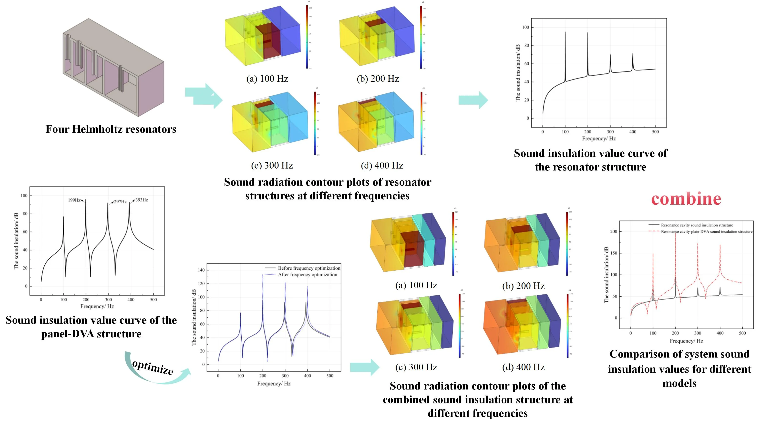
Targeting the low-frequency noise line-spectrum characteristics of substations, the Helmholtz resonance technology is first used to design the sound insulation structure. Four Helmholtz resonators are designed for the four main noise frequencies of 100 Hz, 200 Hz, 300 Hz, and 400 Hz, as shown in Fig. 1. By changing the structural parameters of the resonator, its resonance frequency is adjusted to match the main noise frequency, causing resonance and maximizing sound energy consumption:
Fig. 1Four Helmholtz resonators
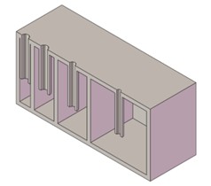
Fig. 2Finite element model of resonator sound insulation structure
The Helmholtz resonance structure design includes five parameters: neck radius , neck length , cavity cross-section length , cavity cross-section width , and cavity height . Considering manufacturing convenience and practical application requirements, three design parameters are determined: neck length , cavity cross-section length , and cavity height . The structural design for different resonator structures is then performed based on their resonance frequencies. First, the neck length is set to 0.02 m, the cavity cross-section length to 0.05 m, and the cavity height to 0.03 m. Then, according to Eq. (1), the neck radius and cavity cross-section width for the 100 Hz, 200 Hz, 300 Hz, and 400 Hz resonators are calculated:
The resulting design parameters are shown in Table 1.
Table 1Helmholtz resonance structure design parameters
Target frequency / Hz | 100 | 200 | 300 | 400 |
Neck radius / m | 0.001 | 0.00145 | 0.00181 | 0.00177 |
Neck length / m | 0.02 | 0.02 | 0.02 | 0.02 |
Cavity length / m | 0.05 | 0.05 | 0.05 | 0.05 |
Cavity width / m | 0.0325 | 0.0179 | 0.0129 | 0.0099 |
Cavity height / m | 0.03 | 0.03 | 0.03 | 0.03 |
To validate the noise reduction effectiveness of the sound insulation structure composed of Helmholtz resonators with different resonant frequencies, an acoustic radiation model of “air-resonator insulation structure-air” was established based on the design parameters in Table 1. The resonator structures are arranged sequentially from right to left for 100 Hz, 200 Hz, 300 Hz, and 400 Hz, simulating the sound transmission model through air-insulation structure-air. Since the insulation structure consists of repetitively arranged units, periodic boundary conditions were applied to the model to ensure acoustic and structural response consistency between the unit and its infinitely repeating adjacent units in space. A unit sound pressure (1 Pa) excitation was applied to the input reference surface on the left side of the model [10] to simulate plane wave incidence. The right side of the model was set with a full transmission (plane wave radiation) boundary condition for calculating the transmitted sound pressure. The simulation was performed using the finite element model shown in Fig. 2.
The simulation was conducted using COMSOL Multiphysics 6.2 for acoustic-structure coupling. The pressure acoustics frequency domain module was employed for the acoustic domain, while the solid mechanics module was used for the structural domain. Second-order tetrahedral elements were adopted as the element type. The maximum element size in the acoustic domain was set to one-sixth of the wavelength at the highest frequency, and the mesh size in the structural domain was 2 mm. The MUMPS direct solver was selected with a relative tolerance of 1×10⁻⁶. The air layer thickness was 33 mm, material damping was modeled using the Rayleigh damping model, the structural loss factor was set to 0.001, and the air sound absorption coefficient was 0.01. A convergence test was performed by progressively refining the mesh (across four levels from coarse to fine) to ensure that the variation in the calculated transmission loss (TL) within the target frequency range (100-400 Hz) was less than 1 dB. Ultimately, a medium-density mesh was selected for subsequent calculations. The material parameters for the resonator sound insulation structure radiation model are shown in Table 2.
Table 2Model materials and parameters
Parameter | Material | |
Steel | Air | |
Density (kg/m3) | 7850 | 1.2 |
Sound speed (m/s) | – | 343 |
Structure plate thickness (mm) | 2 | – |
Young’s modulus (Pa) | 2.16×10¹¹ | – |
Poisson’s ratio | 0.28 | – |
Loss factor | 0.001 | – |
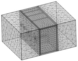
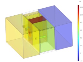
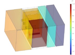
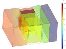
Solving the resonator sound insulation structure model yields the sound field contour plots for different resonance frequencies, as shown in Fig. 3. The sound incidence side of the resonator structure is yellow, and the sound transmission side is blue. This indicates a significant noise reduction effect of the resonator structure, with a clear reduction in noise radiation observed after installing the resonator structure. When sound waves enter the resonator, at frequencies of 100 Hz, 200 Hz, 300 Hz, and 400 Hz, the corresponding designed frequency resonator appears red, indicating the maximum sound pressure level inside the cavity, intense air vibration, and maximum energy consumption, thereby achieving efficient attenuation of the target frequency noise. The data shows that the sound insulation value of the resonator structure model is 95.03 dB at 100 Hz, 94.32 dB at 200 Hz, 70.00 dB at 300 Hz, and 71.61 dB at 400 Hz, demonstrating significant noise reduction. The sound insulation value curve of the structural model at different frequencies is Fig. 4.
Fig. 3Sound radiation contour plots of resonator structures at different frequencies
a) 100 Hz
b) 200 Hz
c) 300 Hz
d) 400 Hz
Fig. 4Sound insulation value curve of the resonator structure
As seen in the figure above, peaks in the sound insulation value curve of the Helmholtz resonator structure occur at 100 Hz, 200 Hz, 300 Hz, and 400 Hz. This indicates that the inherent resonance frequencies of the Helmholtz resonator structure match these peak frequencies, achieving good blocking and attenuation effects on specific frequency sound waves, reflecting the excellent sound absorption capability of the resonator structure. This demonstrates the rationality of the resonator structure design for effective sound insulation and noise control of transformers. During resonance, the vibration of air inside the cavity converts sound energy into other forms of energy, such as heat, through mechanisms like friction between air molecules and viscous resistance, making it difficult for sound waves to propagate through the resonator. This manifests as peaks in the sound insulation curve, signifying outstanding sound absorption and noise reduction effects for the corresponding frequencies, thereby reducing the radiation intensity of low-frequency line-spectrum noise.
2.2. Dynamic vibration absorption design
The Dynamic Vibration Absorber (DVA) is suitable for vibration and noise reduction of power equipment dominated by line-spectrum noise radiation. It is installed on the surface of the sound insulation panel to reduce vibration and consequently lower noise radiation levels, achieving precise control of low-frequency line-spectrum noise.
To verify the noise reduction effect of the DVA, a sound radiation model is established with four DVAs attached to the inner surface of the sound insulation panel via a lumped mechanical system. Each DVA was modeled as a mass-spring-damper system with a damping ratio of 0.05. The installation positions were symmetrically arranged around the center of the sound insulation panel, with specific coordinates (unit: m) as follows: 100 Hz DVA: (0.018, 0.013), 200 Hz DVA: (0.055, 0.013), 300 Hz DVA: (0.055, 0.038), 400 Hz DVA: (0.018, 0.038). The natural frequencies of the DVAs were set to 100 Hz, 200 Hz, 300 Hz, and 400 Hz, respectively, with a mass of 0.05 kg. The stiffness values were defined as: 1.97×10⁴ N/m, 7.90×10⁴ N/m, 1.78×10⁵ N/m, 3.16×10⁵ N/m. The Young’s modulus was set to 2.16×10¹¹ Pa, Poisson’s ratio to 0.28, and the loss factor to 0.01. The sound insulation value curve of the radiation model is shown in Fig. 5.
As seen in the Fig. 5, after installing four DVAs with different natural frequencies on the panel, four peaks appear in the sound insulation curve of the model within the analysis frequency band, showing a clear sound insulation effect. The first peak occurs at 100 Hz. However, the anticipated second, third, and fourth peaks did not appear at 200 Hz, 300 Hz, and 400 Hz, but shifted to 199 Hz, 297 Hz, and 393 Hz. This shift is due to the coupling effect between the installed DVAs and the panel, causing a change in modal behavior and a shift in the effective frequency range. Therefore, the natural frequencies of the DVAs need to be optimized to achieve optimal control of the power equipment's radiated noise.
For controlling the 200 Hz, 300 Hz, and 400 Hz noise radiation of power equipment, the natural frequencies of the DVAs are optimized based on literature. The basic parameters of the optimization model are shown in Table 3.
Table 3Parameters for optimizing the natural frequency of the DVA model
Parameter | Definition |
Objective | Sound insulation value at 200 Hz, 300 Hz, 400 Hz |
Optimized param | Natural frequency of DVA |
Parameter range | 150 Hz-250 Hz; 250 Hz-350 Hz; 350 Hz-450 Hz |
Initial value | 200 Hz, 300 Hz, 400 Hz |
Optimization tolerance | 0.01 |
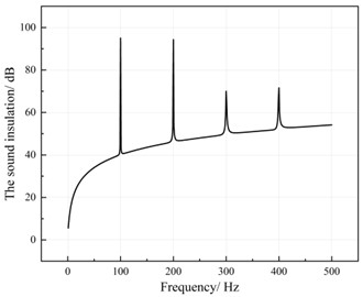
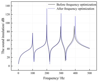
Based on the above parameters, the optimization of the DVA natural frequencies is performed. The system sound insulation value curve after optimizing the DVA natural frequencies is shown in Fig. 6.
As seen in the figure above, after optimizing the natural frequencies of the DVAs, the system sound insulation value reaches its maximum at 100 Hz, 200 Hz, 300 Hz, and 400 Hz, showing a significant improvement compared to before optimization. The optimized DVA natural frequencies precisely match the main noise frequencies of the transformer, inducing resonance and causing the DVA mass to vibrate intensely. The sound insulation panel remains stationary. The energy acting on the panel, causing it to vibrate and radiate noise, is transferred to the DVA. The vibration energy borne by the panel is greatly reduced, and its vibration amplitude decreases sharply. Since vibration amplitude is positively correlated with noise radiation, this results in a substantial reduction in the overall noise radiation from the transformer.
Fig. 5Sound insulation value curve of the panel-DVA structure
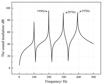
Fig. 6System sound insulation value after DVA natural frequency optimization
2.3. Combined sound insulation structure design
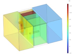
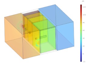
To maximize the sound insulation performance of the structure, the Helmholtz resonance technology and dynamic vibration absorption technology are combined. A “resonator structure-panel-DVA” sound model is established, set with periodic boundaries. The left side of the model is defined as a unit sound pressure input. Simulation calculations yield the sound field contour plots for different resonance frequencies, as shown below:
Fig. 7Sound radiation contour plots of the combined sound insulation structure at different frequencies
a) 100 Hz
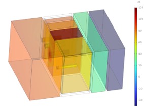
b) 200 Hz
c) 300 Hz
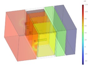
d) 400 Hz
From the figures above, the sound incidence side of the combined structure is orange-yellow. When sound waves enter the resonator, the resonator corresponding to the designed frequency (100 Hz, 200 Hz, 300 Hz, 400 Hz) appears red, indicating the maximum sound pressure level and achieving efficient attenuation of the target frequency noise. After passing through the resonator sound insulation structure, the sound waves appear blue-green, showing a clear sound insulation effect. After continuing through the panel with attached DVAs, the sound waves appear dark blue, indicating excellent sound insulation performance of the combined structure. The data shows that the sound insulation values of the combined structure model are 149.7 dB at 100 Hz, 196.88 dB at 200 Hz, 172.14 dB at 300 Hz, and 169.97 dB at 400 Hz, demonstrating significant noise reduction. The sound insulation value curve of the structural model at different frequencies is shown in Fig. 8.
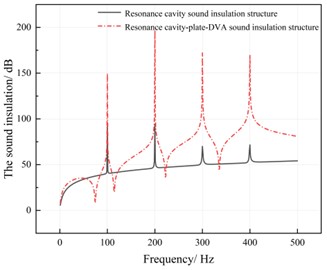
As seen in the Fig. 8, after combining the Helmholtz resonator sound insulation structure with the panel attached with DVAs, its sound insulation performance is greatly enhanced compared to the single resonator structure. The sound insulation value increased by 54.67 dB at 100 Hz, 102.56 dB at 200 Hz, 102.14 dB at 300 Hz, and 98.36 dB at 400 Hz. The Helmholtz resonator structure, based on acoustic resonance principles, strongly absorbs and blocks sound waves of specific frequencies. The panel with attached DVAs controls vibration. The natural frequencies of the DVAs precisely match the main noise frequencies of power equipment like transformers, efficiently consuming the vibration energy responsible for noise radiation under resonant conditions, thereby controlling noise. The synergistic effect of the two technologies significantly enhances the sound insulation performance of the combined acoustic system compared to a single Helmholtz resonator structure, reducing noise from different angles. This verifies the feasibility of the multi-resonance-based sound insulation structure design for power equipment.
Fig. 8Comparison of system sound insulation values for different models
3. Conclusions
This paper conducted a design study on a multi-resonance-based sound insulation structure for power equipment, targeting their low-frequency line-spectrum noise characteristics. Helmholtz resonance sound insulation design, dynamic vibration absorption sound insulation design, and combined sound insulation design were performed separately. Acoustic models were established for optimal design, analysis, and verification, leading to the following conclusions:
1) The Helmholtz resonance design for the sound insulation structure showed that the inherent resonance frequencies of the Helmholtz resonator structure matched the peak frequencies in the sound insulation value curve within the analysis band. This verifies the good sound absorption performance of the resonator structure, its excellent sound absorption and noise reduction effect for corresponding frequency sound waves, and its reduction of low-frequency line-spectrum noise radiation intensity.
2) After the dynamic vibration absorption design for the sound insulation panel, coupling effects caused a shift in the effective frequency of the DVAs. Following frequency optimization, the vibration energy of the panel decreased. Since vibration amplitude is positively correlated with noise radiation, the noise radiation control effect is significant.
3) After integrating Helmholtz resonance technology with dynamic vibration absorption technology in the sound insulation design, both approaches collaboratively reduce noise from different perspectives, demonstrating significant synergistic noise reduction effects. The hybrid acoustic system exhibits substantially enhanced sound insulation performance, achieving transmission loss values of 149.7 dB, 196.88 dB, 172.14 dB, and 169.97 dB at 100 Hz, 200 Hz, 300 Hz, and 400 Hz, respectively. These results represent improvements of 57.5 %, 108.7 %, 145.9 %, and 137.3 % compared to the standalone Helmholtz resonator structure, validating the feasibility of the multi-resonance-based sound insulation design for power equipment.
References
-
X. Wang, B. Yang, J. You, and Z. Gao, “Coarse-fine adaptive tuned vibration absorber with high frequency resolution,” Journal of Sound and Vibration, Vol. 383, pp. 46–63, Nov. 2016, https://doi.org/10.1016/j.jsv.2016.07.030
-
G.-Q. Di, X.-X. Zhou, and X.-W. Chen, “Annoyance response to low frequency noise with tonal components: A case study on transformer noise,” Applied Acoustics, Vol. 91, pp. 40–46, Apr. 2015, https://doi.org/10.1016/j.apacoust.2014.12.003
-
Q. Wang et al., “Dual-function quasi-zero-stiffness dynamic vibration absorber: Low-frequency vibration mitigation and energy harvesting,” Applied Mathematical Modelling, Vol. 116, pp. 636–654, Apr. 2023, https://doi.org/10.1016/j.apm.2022.12.007
-
B. Mohammad Reza, “Mechanics of electrical transmission line robot inspector: pendulum as a dynamic vibration absorber,” in E3S Web of Conferences, Vol. 162, p. 03004, Apr. 2020, https://doi.org/10.1051/e3sconf/202016203004
-
M. R. Jolly and J. Q. Sin, “Passive tuned vibration absorbers for sound radiation reduction from vibrating panels,” Journal of Sound and Vibration, Vol. 191, No. 4, pp. 577–583, Apr. 1996, https://doi.org/10.1006/jsvi.1996.0141
-
J. Ma, J. Wu, M. Geng, B. Ma, and C. Shen, “Optimal analysis on low frequency line spectrum sound control of power equipment using dynamic vibration absorber,” Vibroengineering Procedia, Vol. 41, pp. 117–123, Apr. 2022, https://doi.org/10.21595/vp.2022.22535
-
M. Geng, J. Ma, Y. Jing, Y. Zhao, and L. Wang, “A position optimization strategy of the dynamic vibration absorber for the noise control of the power equipment,” Vibroengineering Procedia, Vol. 47, pp. 16–22, Dec. 2022, https://doi.org/10.21595/vp.2022.23030
-
D. Wu, N. Zhang, C. M. Mak, and C. Cai, “Hybrid noise control using multiple Helmholtz resonator arrays,” Applied Acoustics, Vol. 143, pp. 31–37, Jan. 2019, https://doi.org/10.1016/j.apacoust.2018.08.023
-
S.-H. Seo and Y.-H. Kim, “Silencer design by using array resonators for low-frequency band noise reduction,” The Journal of the Acoustical Society of America, Vol. 118, No. 4, pp. 2332–2338, Oct. 2005, https://doi.org/10.1121/1.2036222
-
J. Ma et al., “Research on noise reduction methods for indoor substations based on resonant sound absorption,” Vibroengineering Procedia, Vol. 54, pp. 167–173, Apr. 2024, https://doi.org/10.21595/vp.2024.24080
About this article

The authors have not disclosed any funding.
The datasets generated during and/or analyzed during the current study are available from the corresponding author on reasonable request.
The authors declare that they have no conflict of interest.
