Abstract
This study explains the challenges of reconstructing a continuous beam bridge and its effects on the performance of adjacent structures. Combined in-situ demolition and modification of continuous beam bridges with the new construction of steel truss arch bridges, an integrated construction method is established. Taking a bridge as a construction platform, the temporary fixation technology is used for the tie beam hook. Various erection techniques of the bridge and tie beam construction support frame, as well as the construction techniques of Truss steel arch and wind bracing are studied and explored. In addition, the method of simultaneous disassembly and construction methods of crossbeams are also studied. Finally, a new technology is developed to reconstruct Truss arch bridge on continuous beam bridges.
1. Introduction
In the regulation of inland waterways, bridges that span these waterways should satisfy the requirements of the waterway planning, especially in terms of navigational clearance width and height. Most inland river bridges are multi-span structures, and piers in the river channel can obstruct navigational capacity. The main solution method is to demolish the multi-span bridges with piers and construct new single-span bridges at the original locations [1-3]. However, the risks associated with the demolition of bridges are difficult to predict and may lead to safety accidents.
The construction safety of bridge reconstruction has always been a prominent topic. Zu et al. [4] focused on the CRTS II ballast less track high-speed railway simply supported beam bridges and developed a sample database of post-earthquake residual track geometric irregularities based on the randomness of earthquakes. Gao et al. [5] studied the replacement of bearings for a continuous curved bridge in Lin’an, Zhejiang, China. They proposed a design scheme, construction technology, and a monitoring technology for replacement without interrupting traffic. Han et al. [6] studied a new type of corrosion-resistant steel A709-50CR for replacing girders. They conducted a dual objective optimization based on reliability and risk on a multi beam carbon steel bridge to determine the optimal timing and selection for replacing carbon steel beams. Seyed et al. [7] analyzed the effects of different alternatives for the upper and lower structural systems on the progressive collapse procedure after verifying the bridge collapse procedure. Mashhadi et al. [8] compared the life cycle cost of reinforcing steel bridges through post-installed shear connectors with the life cycle cost of bridge reconstruction. Zhu et al. [9] conducted an experiment on the application of UAV-based LiDAR-RGB data fusion in bridge reconstruction to evaluate its effectiveness in monitoring bridge construction. It is evident that the above studies on bridge reconstruction mainly focus on the application of new technologies, and lack a comprehensive summary of construction techniques under complex working conditions, especially on in-situ reconstruction of bridges.
The main objectives of this study are: 1) To present the integrated construction method for in-situ reconstruction of a continuous girder bridge; 2) To detail the key technologies used for load reduction and reinforcement of bridges and construction of new steel truss arch bridges; 3) To discuss the practical implementation and safety considerations based on the Yanpingtang Bridge case.
2. Project overview
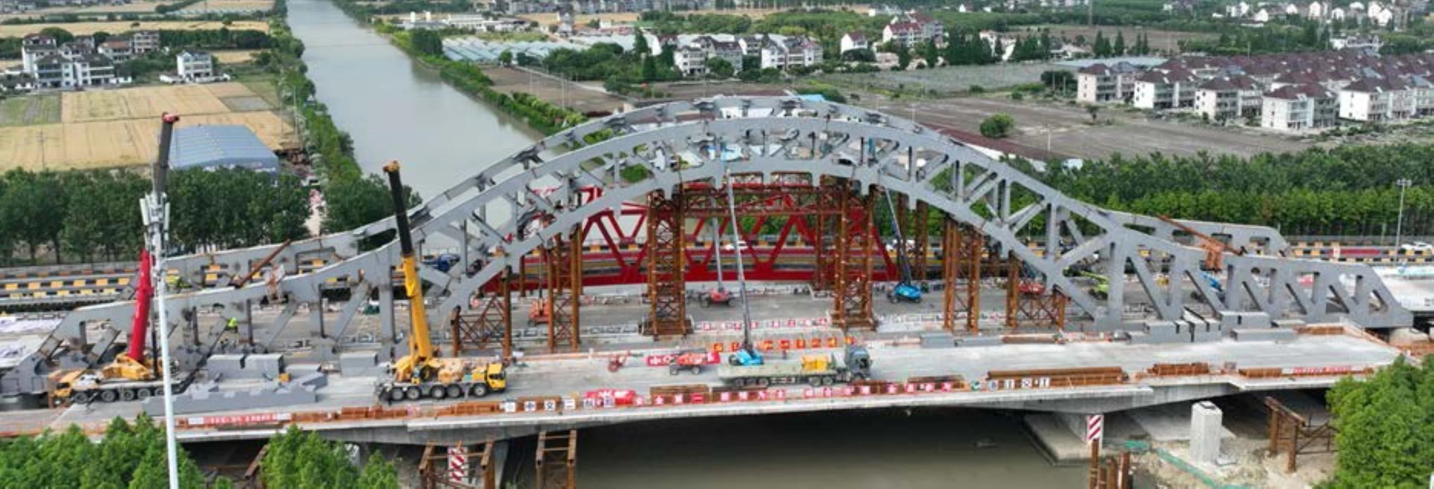
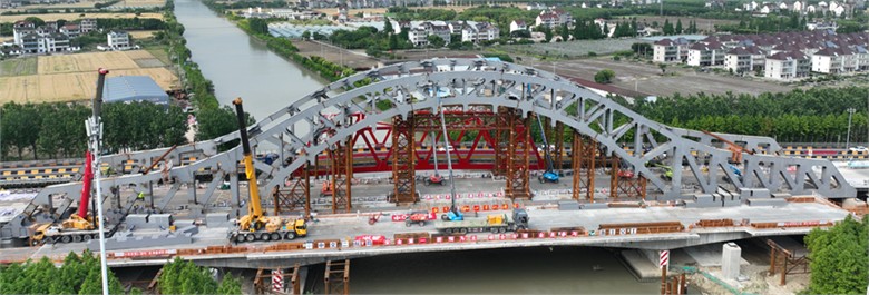
The project is located on Provincial Highway 07 in Pinghu, Jiaxing. The designed maximum navigable water level is 1.96 m, and the original bridge has a navigational clearance of 5.5 m and a height of less than 7 m. This configuration renders it inadequate to meet current requirements. Therefore, this bridge will be demolished and replaced with a new steel truss arch bridge. These demolished structures include the main bridge and the 20-meter approach bridges on both sides. The construction site is shown in Fig. 1. In this project, this bridge was utilized as a construction platform. A support structure was erected at the mid-span to facilitate the construction of the central 45-meter section of the new truss arch bridge. After the upper arch ribs of the main span of the new bridge were completed, the mid-span girders of this bridge were dismantled in sections, while the mid-cross beams of the new bridge were installed at the same time. After dismantling the mid-span of this bridge, the side spans were removed. Deck demolition mainly involves cutting and removes the flanges, top slabs, web slabs, and bottom slabs of the bridge.
Fig. 1Construction site of the project
3. Key construction technologies
3.1. Load reduction and reinforcement of the bridge
To prevent overloading during construction, the following measures were implemented (see Fig. 2):
(1) A milling machine was utilized to remove asphalt from the bridge deck, thereby reducing the load by 3.3 tons per meter.
(2) The guardrails on both sides were horizontally cut, resulting in a load reduction of 1 ton per meter.
(3) Steel pipe columns were installed under the bridge for reinforcement to support the new loads generated during the construction.
3.2. Installation of the support structure
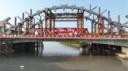
After the assembly of side-span steel truss arch was completed, the lower brackets, side stringers, upper brackets, and end segment of the main-span steel truss arch were installed on the main-span side of the side-span steel truss arch from the bottom to the top. A stiffener was installed on the web, and another stiffener was placed on the top/bottom plates of the side-span and main-span steel truss arch segments. For the side and intermediate stringer segments, two stiffeners were installed on the webs, and one stiffener was placed on the top/bottom plates. First, approach spans were installed on both ends of this bridge deck, followed by pile driving and the erection of temporary supports. Then multiple segments of the side-span steel truss arch were sequentially assembled on the temporary supports. This operation was carried out from the lower chord to the upper chord of the arch rib to complete the closure of the side-span steel truss arch. Lower brackets were installed on the main-span of the completed side-span steel truss arch. Side stringers were installed on the top of the lower brackets near the bridge deck. Finally, the upper brackets were mounted on the top of the side stringers and the far side (opposite the deck) of the lower brackets, and then the end segment of the main-span steel truss arch was installed on the upper brackets. The support system is shown in Fig. 3.
Fig. 2Milling site conditions
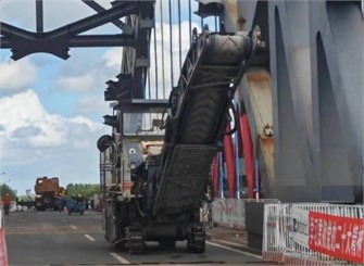
a) Milling machine on site

b) Road surface after milling
Fig. 3Support system
3.3. Tie beam construction
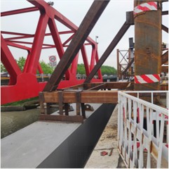
After installing a cantilevered deck support on the bridge deck, the segments in the middle tie beam were lifted to the closure position using the cantilever. The segments were adjusted to complete the closure of the tie beam. Specifically, a cantilevered deck support was installed on the bridge deck, and steel wire ropes suspended on the cantilever were used as hooks to temporarily fix multiple intermediate beams. This allows for the adjustment and overall connection of segments during the temporary fixation of middle and side tie beams. After the closure of the tie beam, the connection between the cantilever and the middle tie beam was removed. The on-site situation is shown in Fig. 4.
3.4. Construction of main span steel truss arch
The middle segments of the main-span steel truss arch were erected on the upper support and deck support to close the main-span steel truss arch. According to the sequence from the side spans to the mid-span, the lower chords of multiple middle segments of the main-span steel truss arch were symmetrically erected on the upper and deck supports. Subsequently, the upper chords of these segments were symmetrically erected on the lower chords, thereby completing the closure of the main-span steel truss arch.
Fig. 4Connecting the tie beam to the cantilevered deck support
3.5. Installation of temporary wind bracing and hangers
Temporary wind bracing and hangers were installed. After the upper support and deck support were removed, the hangers were tensioned, and the lower support was dismantled. Specifically, temporary wind bracing was symmetrically installed between the main-span steel truss arches on both sides of the bridge, following a sequence from the mid-span to the side spans. After the hangers were installed, the upper and deck supports were removed, the hangers were tensioned three times, and the lower support was dismantled.
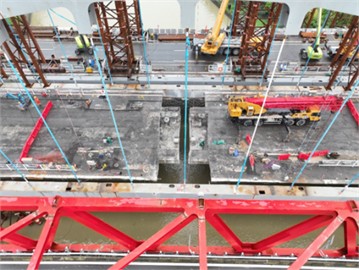
3.6. Removal of the bridge deck and installation of cross beams
The closure segment of the bridge deck was removed first, and then the middle cross beams of the new bridge were installed. The cutting sequence for the bridge deck is organized as: (1) side flanges, (2) middle top plate, (3) bottom plate, and (4) side webs. The weight of each piece is less than 10 tons. In addition, the legs of the 70 ton crane should not extend to Building 8 and should be kept as far away as possible from the middle of the span to minimize overturning moment. The parameters of the closure segment are shown in Table 1.
According to the symmetrical strategy, the concrete at the mid span was cut into 3-meter-long segments. After each segment of the concrete beam was cut, a cross beam was installed. The maximum weight of the cross beam was 25 tons. A 100-ton crane with a rotation radius of 9 meters, a boom length of 12 meters, and a rated lifting capacity of 27 tons was utilized to meet the requirements of lifting.
Table 1Parameters for the closure segment
Closure segment | Elements | Area (m2) | Length (m) | Weight (T) |
Flange | 1.84 | 2 | 9.568 | |
Top plate | 1.88 | 2 | 9.776 | |
Bottom plate | 1.66 | 2 | 8.632 | |
Web | 1.86 | 2 | 9.672 |
After dismantling the mid-span closure segment, the first middle cross beam was installed using two 70-ton cranes. The outriggers with a counterweight of 1.9 tons, a radius of 10 meters, a boom length of 20 meters, and a lifting capacity of 16.2 tons were located at the end of Block 7. The calculated load was 25.9 tons, and the middle cross beam weighs 19.5 tons. Then the main span segments (8-1) were gradually removed, and the middle cross beams of the new bridge were installed at the same time.
Fig. 5Removal of the bridge deck
4. Conclusions
The technology of reconstructing a continuous girder bridge into a steel truss bridge is studied. To facilitate the construction of the new bridge, the following measures should be implemented: A milling machine should be used to remove the bridge deck asphalt, thereby reducing the load by an average of 3.3 tons per meter. In addition, the guardrails on both sides should be horizontally cut to reduce the load by an average of 1 ton per meter. Steel pipe columns should be installed under the bridge for reinforcement to meet the construction load requirements of the new bridge.
References
-
G. Qin, Y. Zhou, K. Hu, D. Han, and C. Ying, “Automated reconstruction of parametric BIM for bridge based on terrestrial laser scanning data,” Advances in Civil Engineering, Vol. 2021, No. 1, p. 88993, Jan. 2021, https://doi.org/10.1155/2021/8899323
-
M. Fu, Y. Liang, Q. Feng, B. Wu, and G. Tang, “Research on the application of multi-source data analysis for bridge safety monitoring in the reconstruction and demolition process,” Buildings, Vol. 12, No. 8, p. 1195, Aug. 2022, https://doi.org/10.3390/buildings12081195
-
Q. Huang, X. Wu, Y. Zhang, and M. Ma, “Proposed new analytical method of tower load in large-span arch bridge cable lifting construction,” Applied Sciences, Vol. 12, No. 18, p. 9373, Sep. 2022, https://doi.org/10.3390/app12189373
-
L. Zu et al., “Time-frequency characteristics investigation and numerical reconstruction of seismic-induced track irregularity for high-speed railway bridge,” Structures, Vol. 58, p. 105359, Dec. 2023, https://doi.org/10.1016/j.istruc.2023.105359
-
H. Gao, J. Jian, B. Li, Y. Sun, and H. Liu, “Design, construction and monitoring of continuous curved box girder bridge during bearing replacement-case study,” Structure and Infrastructure Engineering, pp. 1–25, Oct. 2023, https://doi.org/10.1080/15732479.2023.2266725
-
X. Han, D. Y. Yang, and D. M. Frangopol, “Optimum maintenance of deteriorated steel bridges using corrosion resistant steel based on system reliability and life-cycle cost,” Engineering Structures, Vol. 243, p. 112633, Sep. 2021, https://doi.org/10.1016/j.engstruct.2021.112633
-
A. Seyed Khoei, R. Akbari, S. Maalek, and A. Gharighoran, “Assessment of design and retrofitting solutions on the progressive collapse of Hongqi bridge,” Shock and Vibration, Vol. 2020, pp. 1–13, Sep. 2020, https://doi.org/10.1155/2020/4932721
-
A. H. Mashhadi, A. R. G. Azad, and M. Tavakolan, “Life cycle cost comparison of strengthening a steel bridge using post-installed shear connectors with bridge reconstruction,” International Journal of Construction Management, Vol. 23, No. 8, pp. 1311–1322, Jun. 2023, https://doi.org/10.1080/15623599.2021.1969323
-
Y. Zhu, J. C. Brigham, and A. Fascetti, “LiDAR-RGB data fusion for four-dimensional UAV-based monitoring of reinforced concrete bridge construction: case study of the fern hollow bridge reconstruction,” Journal of Construction Engineering and Management, Vol. 151, No. 1, p. 05024, Jan. 2025, https://doi.org/10.1061/jcemd4.coeng-15411
About this article

The authors have not disclosed any funding.
The datasets generated during and/or analyzed during the current study are available from the corresponding author on reasonable request.
The authors declare that they have no conflict of interest.
