Abstract
The aim of this research is to scientifically substantiate the operating conditions of small and medium-power auxiliary asynchronous electric motors currently in use on mainline electric locomotives of the VL60, VL80, and Ermak 3ES5K types. The goal is to draw conclusions based on scientific research, such as evaluating the operational efficiency of auxiliary asynchronous electric motors and creating the possibility to predict their service life based on the assessment results. This, in turn, will enable timely maintenance of auxiliary engines in locomotives.
Highlights
- When studying asynchronous electric motors, the use of electromagnetic differential equations, primarily considering instantaneous electromagnetic phase quantities, clearly demonstrates the motor's instantaneous operating state.
- The effectiveness and accuracy of the system were tested using a simulation model and compared with the results of experimental studies. According to the comparison results, after modernization, the efficiency of auxiliary asynchronous electric motors in electric locomotives increased by 6.8%.
- . To obtain the overall result, the superposition method should be applied. This requires adding the instantaneous values of the currents obtained in the same corresponding marked phases of the stator and rotor.
1. Introduction
Increasing the operational reliability of asynchronous electric motors depends on the operating principles of each of its electrical and mechanical components. From this perspective, enhancing the reliability of asynchronous electric motors directly leads to an increase in their service life. In this regard, the method of symmetrical components, developed by the American scientist C.L. Fortescue in the 1920s, became popular. The development of this method is described in detail in the works of Yu.S. Chechet and I.M. Kamen. In this approach, the principle of superposition is applied to study electrical machines using the method of symmetrical components, and the phase currents are separated into direct and reverse sequence components, forming circular rotating fields. In the 1950s, B. Geller and V. Gamat demonstrated that it is possible to account for high-harmonic magnetic fields, which can cause additional torques and losses, resulting in the deterioration of mechanical characteristics while improving the overall performance of an asynchronous electric machine. Y.B. Danilevich and E.G. Kasharskiy examined the issue of additional losses occurring in asynchronous motors due to the presence of high-harmonic magnetic fields in the air gap, which leads to a decrease in the efficiency of electric machines.
The aforementioned methods for studying asynchronous electrical machines are based on the symmetry of the motor rotor's electrical circuit. However, the manufacturing technology of the rotor winding in the production of the auxiliary asynchronous electric motor ANE-225 is compromised, which can lead to an asymmetrical distribution of currents in the rotor slot bars. In auxiliary asynchronous motors of the ANE-225 type used in electric locomotives, the electrical circuit of the rotors is asymmetrical due to a fundamental violation of their manufacturing technology. Therefore, to study the operation of auxiliary asynchronous electric motors in electric locomotives with rotor defects, a methodology is required that takes into account the uneven distribution of currents in the short-circuited rotor slots [1-3].
2. Methodology
Before investigating the operation of short-circuited rotors in auxiliary asynchronous electric motors of mainline electric locomotives, it is necessary to develop a system of equations corresponding to the physical laws of this motor in both damaged and undamaged states. When creating this physical system, equations are formulated for the instantaneous voltage drop and magnetic flux acting on the copper stator windings and the aluminum rods of the rotor in an asynchronous motor [4].
The voltage balance equations in the stator and rotor phases of an auxiliary asynchronous electric motor are written in various forms. In this model, based on the laws of electromagnetic induction, the improvement of the method for modeling instantaneous electromagnetic phase quantities for each rotor rod is expressed by the following equation.
For stator windings:
For rotor shafts:
where , , – instantaneous values of phase voltages at the terminals, – phase current in A (a), () – magnetic flux in phase A (a), () – active resistance in the stator phase (a-rotor phase), , , – instantaneous values of voltages at the terminals of stator winding phases.
Let us consider the expression that represents the instantaneous electromagnetic phase quantities in the stator windings of this asynchronous motor and its harmonic variation in the AC circuit with respect to the active resistance:
If the voltage change in the stator windings of an auxiliary asynchronous electric motor follows the law , and the current change follows the law , then represents the phase shift between voltage and current in this part of the circuit, and is called the power factor for this circuit.
The voltage supplied to the asynchronous electric motor can be written as follows, based on Eq. (3), in terms of its distribution across the phases of the stator windings:
The influence of the magnetic flux in the engine phases on the stator windings is expressed by the following equations:
where, , , represent the voltages supplying the stator phases; , , , , , , current strength and magnetic flux coupling in the stator (rotor) phases.
The influence of the magnetic flux in the stator phases on the rotor windings is expressed by the following equations [5]:
By incorporating the differential equations for magnetic flux in the stator and rotor, developed for auxiliary asynchronous electric motors in electric locomotives, into the physical model created using MatLab Simulink software, we can obtain the following diagram.
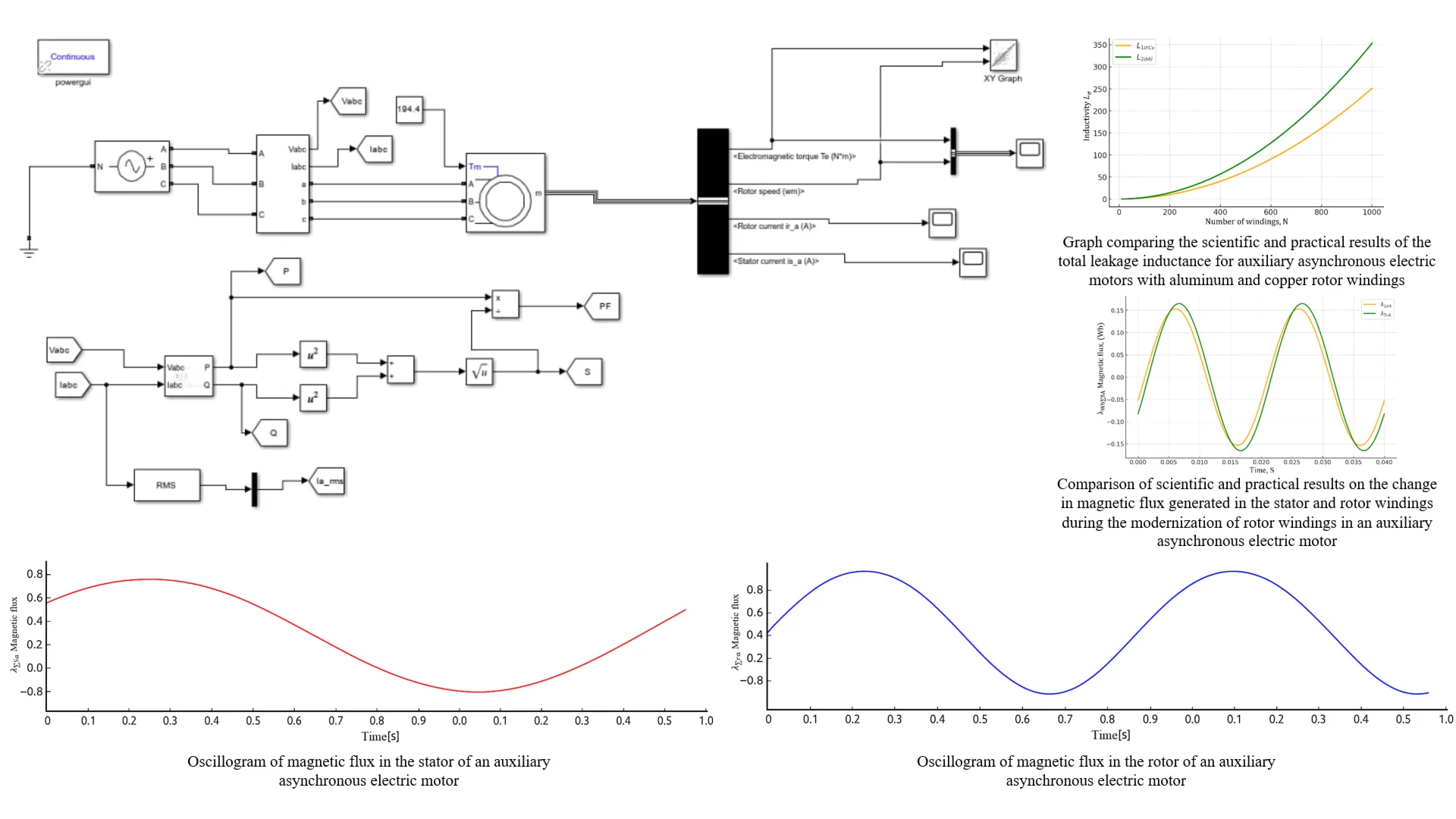
Fig. 1Oscillogram of magnetic flux in the stator of an auxiliary asynchronous electric motor
The graph depicts – the magnetic flux of the stator phase as a function of time (). This condition indicates a stable electromagnetic state. Such a change occurs as a result of balanced stator phase currents. In physical terms, this graph illustrates the rotation process of the magnetic field and the continuous exchange of electromagnetic energy [6-8].
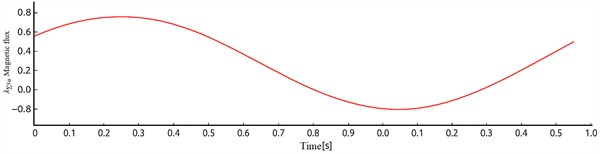
This graph illustrates the temporal variation of magnetic flux in the rotor phase of an auxiliary asynchronous electric motor in electric locomotives. The flux changes in a sinusoidal pattern. As evident from the graph, the magnetic flux exhibits a sinusoidal variation. One cycle 0.5 s → 2 Hz. This represents the formation of a rotating magnetic field in the rotor of the asynchronous motor and depicts the process of electromechanical energy conversion [9-11].
Fig. 2Oscillogram of magnetic flux in the rotor of an auxiliary asynchronous electric motor
In this case, if the functions of the stator and rotor windings are known, their leakage inductance is determined using the following formulas:
When the rotor windings of an asynchronous motor are made of aluminum and copper, its total leakage inductance:
where, – leakage inductance in the stator winding field, – leakage inductance in the rotor winding field, – the mutual inductance between the stator and rotor, – total resistance in the phases of the stator windings, – the reduced resistance in the rotor phases.
This model is constructed taking into account the following considerations:
1) The electric machine has a uniform air gap. Therefore, higher spatial harmonics of the magnetic field are not taken into account in this model.
2) All parameters are linear.
3) The source voltages are sinusoidal.
The basic model under consideration, in addition to the main nominal operating modes of the engine, allows for the study of source voltage asymmetry, but has the following drawbacks. In the presence of a reverse rotating field (asymmetric source), the current displacement effect begins to manifest in the rotor bars. In the given set of equations, this effect cannot be properly accounted for separately for reverse fields. This also applies to higher time harmonics of the source voltage, as the current displacement effect is most pronounced in them [12].
3. Results
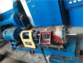
To verify the adequacy of the simulation model developed based on the mathematical model against the test bench results, we will examine the schematic of the physical model device for the test bench. In this setup, a DC motor is primarily connected to an asynchronous motor as a load through a coupling. During the testing process, the DC motor is connected as a load to both types of asynchronous motors (Fig. 3).
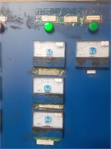
The circuit shown in Fig. 3 is powered by a three-phase 220/380 V 50 Hz voltage supply. When the “Common Source” button is pressed, the K1 relay activates, and the three-phase voltage is transmitted through the K1.3 contacts to the single-phase voltage regulators KR1, KR2, KR3 and the FT1 phase distributor. The first two regulators are used to set the required voltage levels in phases A and B at phase angles of 0° and 120°. The phase distributor is designed to provide the required phase angle at a constant voltage level in phase C. This is intended to supply various levels of asymmetrical power to the AD motor. The KR3 voltage regulator is designed to adjust the excitation voltage of the DTG DC generator to change the load on the motor. This voltage is rectified by the D1-4 diode bridge, filtered by the Kon. capacitor, and supplied to the generator’s excitation winding. Thus, when K1.3 is activated, the initial power supply to the aforementioned regulators is provided to adjust the required voltage levels. To start the machine, the “Start Motor” button is pressed, after which the K2 relay activates and supplies power to the tested asynchronous motor through its K2.3 contacts. The motor is run at idle for 3-5 minutes, and the idle current is checked using devices D1, D2, D3. During this test, the current in the motor's stator phases was as follows: We can see that the stator current of the tested copper rotor asynchronous motor is equal to iSA = 93 A, iSB = 95 A, iSC = 97 A. The results obtained from the auxiliary asynchronous motor in the test are almost identical to those obtained from the above simulation model. This device allows for recording not only phase currents and voltages but also consumed active and reactive power, phase angles of currents and voltages, and higher harmonics of the source voltage. All this information is stored in memory and sent to a computer for further analysis. This is primarily used to verify the adequacy of scientific research and the consistency of the work performed. All this information is stored in memory and sent to the computer for further review [13]. In Fig. 3(b), signals from the sensors shown in Fig. 4(a) can be obtained during the testing process of an auxiliary asynchronous electric motor of the ANE-225-4 type. Fig. 4(c) illustrates the installation setup on a test bench where an asynchronous electric motor and a DC generator are connected via a coupling. Fig. 3(b) and 3(c) were captured by researchers on June 30, 2025, at the testing control station located in the electrical machinery workshop of JSC “Uztemiryulmashta’mir”.
Fig. 3Test stand: a) physical model schematic; b) measuring device; c) AC and DC motor
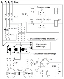
a)
b)
c)
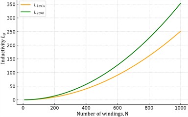
In the research work, it is necessary to compare the theoretical results obtained from the current aluminum state of the rotor windings of the auxiliary asynchronous electric motor under study and its structure with copper rings and rods after modernization with the results of experimental tests. We will compare the total leakage inductance of the auxiliary asynchronous electric motor when its rotor windings are made of aluminum and copper with the results obtained from experimental tests (Fig. 4(a)).
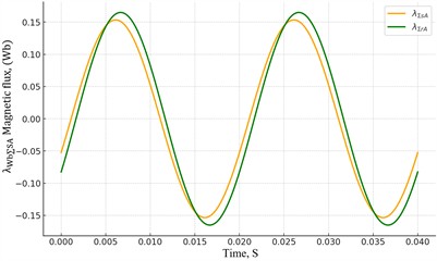
Additionally, the differential equations of magnetic flux in the stator and rotor, written for auxiliary asynchronous electric motors in electric locomotives, were compared with experimental results. The theoretical results obtained from the physical model using MatLab Simulink software were compared with the experimental data in Fig. 4(b).
Fig. 4 graphically illustrate the processes occurring in the rotor of an auxiliary asynchronous electric motor (for example, ANE-225), based on data obtained from a specially developed experimental stand. Using this stand, signals related to parameters such as voltage, current, magnetic flux, and rotational speed in both the stator and rotor circuits were measured. Detailed information about the sensors used in data measurement is provided in Table 1. The comparison results show that when the rotor windings of auxiliary asynchronous electric motors in electric locomotives are made of copper instead of aluminum, the magnetic flux generated in the stator and rotor windings increases by 23 %.
Fig. 4Comparing research results: a) graph comparing the scientific and practical results of the total leakage inductance for auxiliary asynchronous electric motors with aluminum and copper rotor windings; b) comparison of scientific and practical results on the change in magnetic flux generated in the stator and rotor windings during the modernization of rotor windings in an auxiliary asynchronous electric motor
a)
b)
Table 1Sensors used for measurement
Sensor type | Measurement parameter | Operating range | Sensitivity | Accuracy (uncertainty) |
Current transformer | Phase current (A) | 0-20 A | 1 V/A | ±1.5 % |
Voltage sensors | Phase voltage (V) | 0-400 V | 10 mV/V | ±1 % |
Piezoelectric vibration sensor (PCB 352C33) | Oscillatory acceleration (m/s2) | 0-5000 Hz | 100 mV/g | ±2 % |
Optical tachometer | Rotor speed (rpm) | 0-6000 | 0.1 V/100 rpm | ±0.5 % |
The sensors are connected to the data acquisition system (DAS) through an analog-to-digital converter (ADC). Measurements are conducted on separate channels for each phase. The sensor sensitivity and measurement system uncertainty have been pre-calibrated, with the overall measurement uncertainty of the system not exceeding ±2-3 %.
Table 2Comparison of numerical and experimental results
Parameter | Mathematical model (calculation) | Result of the experiment | Difference (%) |
Magnetic flux, | 0.058 | 0.056 | 3.4 |
Scattering inductance, | 0.0142 | 0.0137 | 3.5 |
Rotation speed, rpm | 2950 | 2900 | 1.7 |
Power factor () | 0.84 | 0.81 | 3.6 |
The difference between the numerical and experimental results is less than 5 %, which confirms the adequacy of the developed mathematical model. The disadvantages of the presented methods are as follows:
1) The placement of sensors may not fully detect mechanical vibrations.
2) Electromagnetic noise affects the measurement results.
3) Under asymmetrical power supply conditions, the linearity of the model is not fully maintained.
4) High-speed dynamic oscillations of the rotor disrupt the smoothness of the signal.
5) The model does not take into account the effects of shock absorption and heat.
4. Conclusions
Therefore, to eliminate this shortcoming, it is necessary to implement the following measures:
1) Calculations for the main harmonic of the source voltage and other higher harmonics should be performed separately. It is important to maintain the initial phases of the source voltages for all harmonics.
2) To obtain the overall result, the superposition method should be applied. This requires adding the instantaneous values of the currents obtained in the same corresponding marked phases of the stator and rotor.
3) The current displacement effect is accounted for by introducing the coefficient Kr, which increases the resistance of the rotor winding. This coefficient depends on the slip for the corresponding harmonic of the forward or reverse sequence voltage.
The research work thoroughly examined the change of rotor bars and rings in auxiliary asynchronous electric motors used in locomotives from aluminum to copper material, and possible malfunctions were comprehensively studied. Based on the results obtained from the research work, the following conclusions represent the scientific novelty of the research:
– A mathematical model has been developed that allows calculating the electrodynamic parameters of the motor using differential equations based on the laws of electromagnetic induction for transient processes occurring in auxiliary asynchronous electric motors;
– When studying asynchronous electric motors, the use of electromagnetic differential equations, primarily considering instantaneous electromagnetic phase quantities, clearly demonstrates the motor's instantaneous operating state. Therefore, it is possible to investigate potential malfunctions in the electric motor with high accuracy.
– The effectiveness and accuracy of the system were tested using a simulation model and compared with the results of experimental studies. According to the comparison results, after modernization, the efficiency of auxiliary asynchronous electric motors in electric locomotives increased by 6.8 %.
Based on the obtained scientific research innovations, it is possible to achieve high-performance approaches, such as improving the technical characteristics of asynchronous motors in mainline electric locomotives VL60, VL80, and Ermak 3ES5K, extending their service life, increasing operational reliability, and developing new types of repairs in the production process.
References
-
O. Ergashev, O. Kasimov, S. Djamilov, S. Azimov, and Z. Keldibekov, “Improvement of diagnostics of traction electrical motors of railway rolling stock,” in Problems in the Textile and Light Industry in the Context of Integration of Science and Industry and Ways to Solve Them: PTLICISIWS-2, Vol. 3045, p. 050041, Jan. 2024, https://doi.org/10.1063/5.0197378
-
O. R. Khamidov, I. S. Kamalov, and O. T. Kasimov, “Diagnosis of traction electric motors of modern rolling staff using artificial intelligence,” in The Third International Scientific Conference Construction Mechanics, Hydraulics and Water Resources Engineering (CONMECHYDRO 2021 AS), Vol. 2612, p. 060018, Jan. 2023, https://doi.org/10.1063/5.0125345
-
S. Jamilov, O. Ergashev, M. Abduvaxobov, S. Azimov, and S. Abdurasulov, “Improving the temperature resistance of traction electric motors using a microprocessor control system for modern locomotives,” in E3S Web of Conferences, Vol. 401, p. 03030, Jul. 2023, https://doi.org/10.1051/e3sconf/202340103030
-
O. E. Ergashev and O. R. K. N. K. T. O. T. T. M. E. Abduvakhabov, “Increasing the durability of gear transmissions of asynchronous torsion electric motors,” Web of Scientist: International Scientific Research Journal, Vol. 3, No. 10, pp. 1030–1036, 2022, https://doi.org/10.17605/osf.io/makvn
-
S. F. Jamilov, S. A. Samatov, A. M. Yusufov, S. M. Azimov, and S. X. Abdurasulov, “Analysis of reliability indicators of locomotive traction motors,” in Railway Rolling Stock: Problems, Solutions, Prospects, pp. 145–150, 2023.
-
S. Jamilov, “TSTU modern temperature sensors for the assessment of the permissible thermal state of electric traction machines of a locomotive tractor,” Acta of Turin Polytechnic University in Tashkent, Vol. 13, No. 1, pp. 41–44, 2023.
-
O. Kasimov, S. Fayzibayev, A. Djanikulov, and S. Mamayev, “Numerical studies for estimation of temperature fields in bandage material during locomotive braking,” in Asia-Pacific Conference on Applied Mathematics and Statistics, Vol. 2471, p. 030025, Jan. 2022, https://doi.org/10.1063/5.0089548
-
A. T. Djanikulov and U. I. Safarov, “Correction of ted field weakening switching diagram for mainline diesel locomotives of TED type,” in E3S Web of Conferences, Vol. 401, p. 01071, Jul. 2023, https://doi.org/10.1051/e3sconf/202340101071
-
A. T. Djanikulov and U. I. Abdulatipov, “Torsional oscillations of armature shaft of generator of main diesel locomotive in diesel start-up mode,” in E3S Web of Conferences, Vol. 401, p. 01072, Jul. 2023, https://doi.org/10.1051/e3sconf/202340101072
-
A. Yusufov, O. Khamidov, N. Zayniddinov, and S. Abdurasulov, “Prediction of the stress – strain state of the bogie frames of shunting locomotives using the finite element method,” in E3S Web of Conferences, Vol. 401, p. 03041, Jul. 2023, https://doi.org/10.1051/e3sconf/202340103041
-
O. Khamidov and D. Udalova, “Technical and economic efficiency of intelligent data analysis on the railways of the uzbekistan republic,” in Lecture Notes in Networks and Systems, Cham: Springer International Publishing, 2022, pp. 230–239, https://doi.org/10.1007/978-3-030-96380-4_26
-
S. Abdurasulov, N. Zayniddinov, O. Khamidov, A. Yusufov, and S. Jamilov, “Stress-strain state analysis of cross beam of main frame of industrial electric locomotives PE2M and PE2U,” in The 3rd International Symposium on Civil, Environmental, and Infrastructure Engineering (ISCEIE) 2024, Vol. 3317, p. 060011, Jan. 2025, https://doi.org/10.1063/5.0266927
-
Z. Mukhamedova et al., “Calculating the fatigue strength of load-bearing structures of special self-propelled rolling stock,” Scientific Reports, Vol. 14, No. 1, p. 14, Aug. 2024, https://doi.org/10.1038/s41598-024-70169-0
About this article

The authors have not disclosed any funding.
The datasets generated during and/or analyzed during the current study are available from the corresponding author on reasonable request.
The authors declare that they have no conflict of interest.
