Abstract
The research work focuses on scientifically substantiating the operating conditions of small and medium-power auxiliary asynchronous electric motors used in mainline electric locomotives under JSC “Uzbekistan Railways”. The aim is to provide a scientific basis for the operational efficiency of auxiliary asynchronous electric motors and, based on the research findings, to conduct a practical investigation of their service life. This, in turn, will enable timely maintenance of auxiliary asynchronous electric motors in locomotives. Additionally, it will contribute to improving the performance indicators of auxiliary asynchronous electric motors.
Highlights
- A mathematical model was developed that enables the calculation of the motor's electrodynamic parameters using differential equations based on electromagnetic induction laws for transient processes occurring in auxiliary asynchronous electric motors.
- The method for modeling instantaneous electromagnetic phase quantities of an asynchronous electric motor was improved based on electromagnetic induction law, taking into account the change from aluminum rods and rings to copper construction in the rotor slots.
- The scattered magnetic flux occurring in the stator, rotor, and between the stator and rotor when changing aluminum rods and rings in the rotor slots to copper material was simulated using MatLab Simulink software, and the final conclusions were compared.
1. Introduction
Before investigating the operation of short-circuited rotors in auxiliary asynchronous electric Before investigating the operation of short-circuited rotors in auxiliary asynchronous electric motors of mainline electric locomotives, it is necessary to develop a system of equations corresponding to the physical laws of this motor, both in the presence and absence of damage. When constructing this physical system, equations are formulated for the instantaneous voltage drop and magnetic flux acting on the copper stator windings and aluminum rods of the rotor in an asynchronous motor. Additionally, studies by several foreign scientists on replacing cast aluminum rods and rings in the rotors of auxiliary asynchronous electric motors with copper rods and rings have been examined. In particular, A. I. Zaysev’s method for finding the relationship between the forward and reverse magnetizing forces of a short-circuited rotor allows determining the asymmetry coefficient of the rotor circuit when one or more rods are disconnected. Our research aims to further improve this method by increasing reliability, taking into account changes in the resistance of the entire circuit, not just when breaks occur in individual parts of the aluminum rods in the rotor slot [1].
Writing the differential voltage equilibrium equations for the stator windings of an asynchronous motor in phase coordinates has several advantages:
– All quantities in the system of equations have their own physical meaning and actual values.
– This structure of equations allows accounting for all types of asymmetries in winding parameters and supply voltages.
– It enables the calculation of electromagnetic and electromechanical processes in static and dynamic operating modes when supplied from networks and sources with non-sinusoidal output voltage.
2. Methodology
The voltage equilibrium equations for the stator and rotor phases of auxiliary asynchronous electric motors are expressed in various forms. In this model, the method of simulating instantaneous electromagnetic phase quantities for each stator and rotor is improved based on Kirchhoff's second law, electromagnetic induction, and Ohm's law for a part of the circuit. Let us examine the expression that represents the instantaneous electromagnetic phase quantities in the stator windings of this asynchronous motor and its harmonic variation in the alternating current circuit along the active resistance (Fig. 1).
Fig. 1Instantaneous values for a part of the electrical circuit in an auxiliary asynchronous electric motor
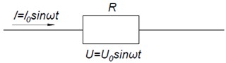
Let’s examine the harmonic oscillations of the current passing through a section of the circuit and its voltage [2]-[4]:
If the voltage change in the stator windings of an auxiliary asynchronous electric motor follows the law , and the current change follows the law , then – represents the phase shift between voltage and current in this part of the circuit, and is called the power factor for this circuit.
Using the harmonic expressions mentioned above, we will examine the instantaneous power value for asynchronous auxiliary electric motors:
The average value of engine power over one cycle, that is, within the time interval :
In active resistance, there is no phase shift between current and voltage changes, i.e., .
The average power during one cycle in active resistance is expressed as follows:
The current and voltage supplied to the stator of an asynchronous electric motor are expressed as follows:
where, , , and , , represent the effective values of sinusoidal (or cosinusoidal) alternating current voltage and current intensity, respectively. These are the root mean square values over one period:
The voltage supplied to the asynchronous electric motor can be written as follows, based on expression (8), in terms of its distribution across the phases of the stator windings:
Therefore, based on Kirchhoff’s second law and electromagnetic laws for asynchronous motors, the voltage applied to the terminals of an auxiliary asynchronous electric motor can be expressed using the formulas and Eq. (6) as follows [5]:
The current strengths and magnetic flux linkages in the stator (rotor) phases are denoted as , , , , , (, , , , , ).
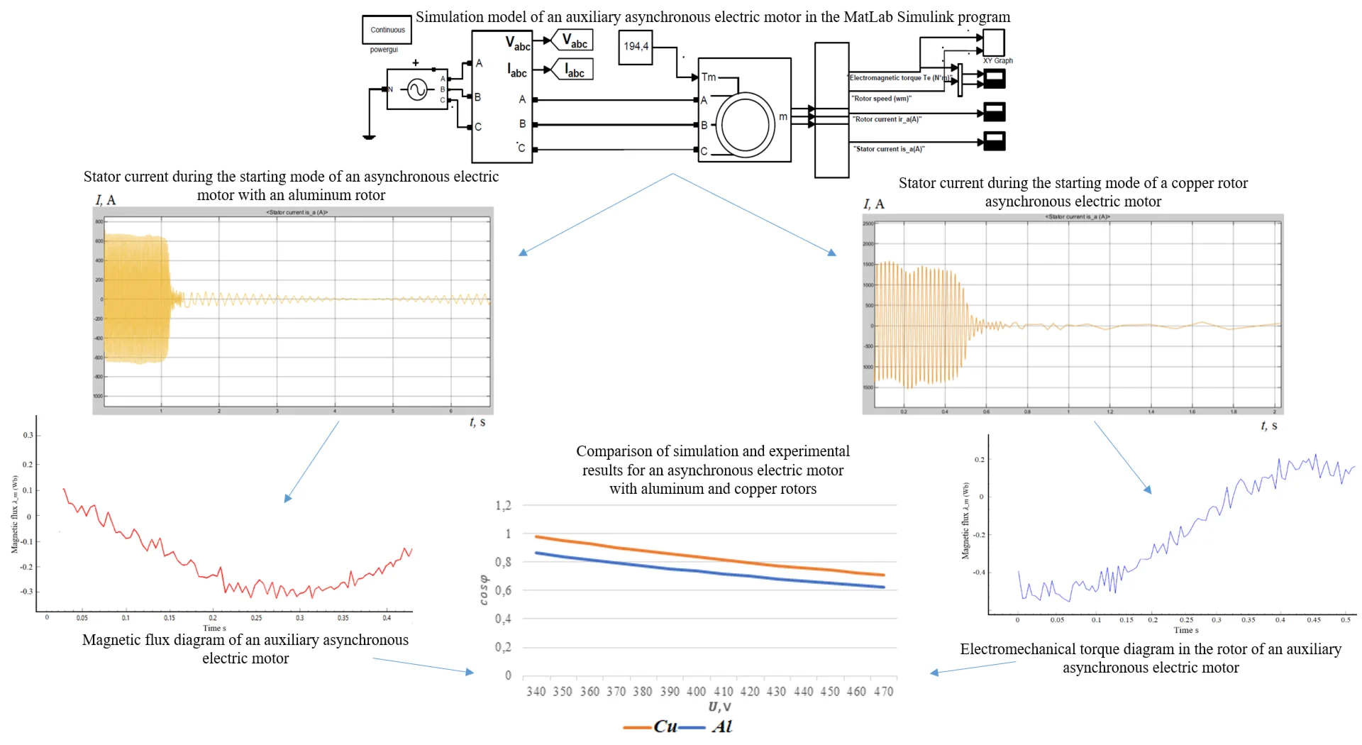
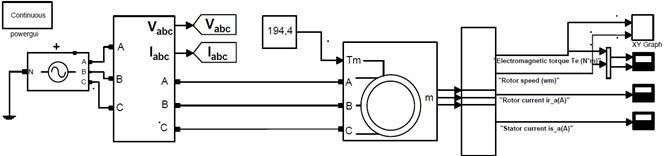
Based on the differential equations compiled on the basis of electromagnetic laws, a simulation model of an auxiliary asynchronous motor was developed in the MatLab Simulink software. In Fig. 2, we can see an emotional model that allows us to analyze the engine [6]
Fig. 2Simulation model of an auxiliary asynchronous electric motor in the MatLab Simulink program
The values obtained from the software and the results of experimental studies are presented in Table 1.
Table 1Comparison of experimental results obtained from an asynchronous motor with an aluminum rotor against the results of the simulation model
Parameters | Stator current | |||||
On the test stand | In an imitation model | On the test stand | In an imitation model | On the test stand | In an imitation model | |
Experiments | 1 | 2 | 3 | |||
iSA | 93 | 92.5 | 94 | 93,8 | 95 | 91 |
iSB | 95 | 94 | 96.5 | 94 | 98 | 95 |
iSC | 97 | 95 | 96 | 93 | 99 | 97 |
iSmax % | 1.015 | 1.02 | 1.032 | |||
Results obtained from the relative error of an asynchronous motor with an aluminum rotor: by the measured stator current – 1.025 %.
Results obtained from the relative error of a copper rotor asynchronous motor: for the measured stator current – 1.013 %.
During the testing of asynchronous motors at the control station, the deviation of the SI parameters in the nominal mode from the established values must not exceed 3 % for current, as stipulated by the requirements of GOST 11828-86 [5]. To determine the adequacy of the results from the simulation model developed based on a mathematical model compared to the results obtained on the test bench, the schematic of the physical model test bench device was examined.
Table 2Comparison of experimental results obtained from a copper rotor asynchronous motor with the results of the simulation model
Parameters | Stator current | |||||
On the test stand | In an imitation model | On the test stand | In an imitation model | On the test stand | In an imitation model | |
Experiments | 1 | 2 | 3 | |||
iSA | 315 | 320 | 298 | 295 | 277 | 275 |
iSB | 320 | 310 | 292 | 285 | 289 | 285 |
iSC | 305 | 300 | 287 | 280 | 294 | 290 |
iSmax % | 1.02 | 1.01 | 1.011 | |||
Fig. 3Stator current during the starting mode of an asynchronous electric motor with an aluminum rotor
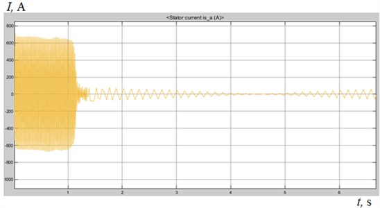
Analysis of the starting process of auxiliary asynchronous electric motors with aluminum rotors. Figure 3 shows the graph of stator current changes during the starting and nominal operating modes of auxiliary asynchronous electric motors with aluminum rotors installed on electric locomotives. For an ANE-225-4 type asynchronous electric motor, the nominal electric current generated in the stator windings is 119 A. Graphical analysis reveals that the current observed when starting the motor is significantly higher than the nominal current, with a considerable difference between them.
It is known that, according to the operating characteristics of asynchronous electric motors, the starting current is typically 4-6 times greater than the nominal value [7]. For this reason, it has been noted that the starting current in the stator of the ANE-225-4 type asynchronous motor with an aluminum rotor reaches 600-660 A. As evident from the graph, during the startup process, the stator current decreases for approximately 1-1.3 seconds before reaching the nominal value.
Analysis of auxiliary asynchronous electric motors with copper rotors. For this motor, Eqs. (10-11), used in the simulation of an asynchronous electric motor with an aluminum rotor, were also applied through the asynchronous motor block in the MATLAB/Simulink software environment. However, adapted coefficients were added to the formulas, taking into account the specific electromagnetic properties of the copper-rotor asynchronous motor.
According to the results of the simulation model, Fig. 4 illustrates the change in stator current during the starting and nominal operating modes of auxiliary asynchronous electric motors with copper rotors in electric locomotives. Due to the rotor windings being made of copper, an increase in the starting current up to 1500-1550 A is observed in these motors. The nominal current value is 119 A. Based on the graph analysis, the starting current in the stator of an asynchronous electric motor with a copper rotor decreases over approximately 0.5 seconds, reaching its nominal value. The conclusions drawn from the results of this simulation can be briefly summarized in Table 3.
Fig. 4Stator current during the start-up mode of a copper rotor asynchronous electric motor
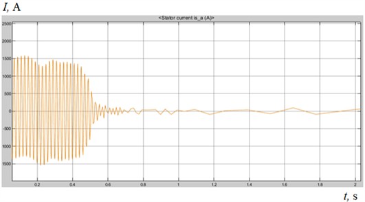
Table 3Comparison of stator current indicators for auxiliary asynchronous electric motors with aluminum and copper rotors
Indicators | Aluminum rotary ANE-225-4 | Copper rotary ANE-225-4 |
Nominal stator current, A | 119 | 119 |
Starting current, A | 600-660 | 1500-1550 |
Time to reach nominal current, s | 1.0-1.3 | ≈ 0.5 |
Threat of heat generation | High | Lower |
Isolation service life | Relatively short | Extended |
Overall operational efficiency | Average | High |
The effect of magnetic flux in the engine phases on the stator windings is expressed by the following equations [7]:
The effect of the magnetic flux in the stator phases on the rotor windings is expressed by the following equations [8]-[10]:
where – leakage inductance in the stator winding field; – leakage inductance in the rotor winding field; – mutual inductance between the stator and rotor.
By incorporating the differential equations of magnetic flux in the stator and rotor, developed for auxiliary asynchronous electric motors in electric locomotives, into the physical model created using MatLab Simulink software, we can obtain the following diagram.
Fig. 5Operating diagrams of an auxiliary asynchronous electric motor
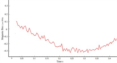
a) magnetic flux diagram of an auxiliary asynchronous electric motor
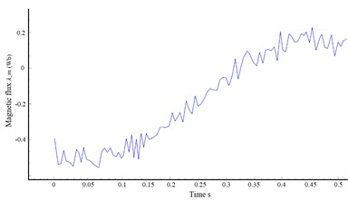
b) Electromechanical torque diagram in the rotor of an auxiliary asynchronous electric motor
Here, USA, USB, USC represent the voltages supplying the stator phases in the auxiliary power circuit of the electric locomotive. The value of this voltage ranges from 280-470 V during operation, with a nominal value of 380 V.
The auxiliary asynchronous electric motor with a short-circuited rotor was installed on a test bench before and after modernization, and control tests were conducted to measure its maximum vibration levels and temperature indicators. The results of these tests are presented in the following Table 4.
Table 4Results obtained for vibration levels and temperature indicators during testing of the ANE-225 electric motor (No. 021) on a test bench at a maximum load current of I= 119 A
No | Before modernization | After modernization | ||
, minute | , °C | , mkm | , °C | , mkm |
0 | 30 | 0 | 30 | 0 |
10 | 37 | 0,15 | 32 | 0,11 |
20 | 42 | 0,19 | 32,9 | 0,15 |
30 | 46 | 0,23 | 33,5 | 0,18 |
40 | 51 | 0,26 | 34,7 | 0,19 |
50 | 57 | 0,3 | 35,9 | 0,2 |
60 | 63 | 0,32 | 37 | 0,22 |
As part of scientific and practical work, to verify the improvement of the short-circuited rotor of the ANE-225-4 electric motor (No. 021), several parameters of the auxiliary asynchronous electric motor were tested in the control and testing area of the Repair and Assembly Shop at JSC “Uztemiryo’lmashta’mir”. The results showed that the vibration indicator of the asynchronous electric motor during operation was 0.13-0.22 μm (up to 0.38 μm as per the test manual), and the temperature in the stator, rotor, and bearing units was 33-37°C (up to 70-80 °C according to the test instructions). Based on these test results, the final conclusion of the test commission members deemed the ANE-225-4 electric motor No. 021 fit for service.
3. Results
This model is constructed taking into account the following considerations:
1) The electric machine has a uniform air gap. Therefore, higher spatial harmonics of the magnetic field are not taken into account in this model.
2) All parameters are linear.
3) The source voltages are sinusoidal.
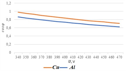
In the research work, graphical comparisons were conducted between simulation and experimental results to more accurately discuss the model’s assumptions and limitations, as well as to enhance interpretability. The power factor was determined for both aluminum-rotor and copper-rotor induction motors.
Based on current technical requirements, the power factor for the aluminum-rotor motor was found to be 0.77, while for the copper-rotor asynchronous motor, it was 0.87. The efficiency of an induction motor (IM) with an aluminum rotor, according to the engine technical specifications, is 90.2 %. The efficiency of an induction motor with a copper rotor, taking into account individual losses, is 95 %.
Fig. 6Comparison of simulation and experimental results for an asynchronous electric motor with aluminum and copper rotors
4. Conclusions
The research work thoroughly examined the replacement of aluminum rotor bars and rings with copper material in auxiliary asynchronous electric motors used in locomotives, and extensively investigated potential malfunctions that may occur. Based on the results obtained from the research work, the following conclusions represent the scientific novelty of the research:
– A mathematical model was developed that enables the calculation of the motor's electrodynamic parameters using differential equations based on electromagnetic induction laws for transient processes occurring in auxiliary asynchronous electric motors.
– The method for modeling instantaneous electromagnetic phase quantities of an asynchronous electric motor was improved based on electromagnetic induction law, taking into account the change from aluminum rods and rings to copper construction in the rotor slots.
– The scattered magnetic flux occurring in the stator, rotor, and between the stator and rotor when changing aluminum rods and rings in the rotor slots to copper material was simulated using MatLab Simulink software, and the final conclusions were compared.
– The effectiveness and accuracy of the system were tested using a simulation model and compared with experimental research results. According to the comparison results, after modernization, the efficiency of auxiliary asynchronous electric motors in electric locomotives increased by 6.8 %.
Based on the obtained scientific research innovations, it is possible to achieve highly effective approaches such as improving the technical characteristics of asynchronous motors in VL60, VL80, and Ermak 3ES5K mainline electric locomotives, extending their service life, increasing operational reliability, and mastering new types of repairs in the production process.
References
-
A. I. Zaytsev, “Study of the influence of rotor rod defects on the operation of an asynchronous short-circuited electric motor and development of a method for their detection,” Tomsk, 1967.
-
A. I. Voldeck, Electric Machines. Leningrad: Energy, 1978.
-
A. V. Ivanov-Smolensky, Electric Machines. Moscow: MEI Publishing House, 2004.
-
A. V. Ivanov-Smolensky, Y. V. Abramkin, A. I. Vlasov, and V. A. Kuznetsov, Universal Method for Calculating Electromagnetic Processes in Electrical Machines. Moscow: Energoatomizdat, 1986, pp. 87–124.
-
O. E. Ergashev, O. T. Kasimov, M. E. Abduvahobov, B. T. Kulmanov, and S. T. Samatov, “Development of a mathematical model for calculating the resistance generated when the rotor rods and rings of auxiliary asynchronous electric motors are made of various materials,” Acta of Railway Transport: Current Issues and Innovations, pp. 108–116, 2021.
-
O. T. Kasimov, O. E. Ergashev, S. B. Namozov, B. T. Kulmanov, Z. O. Keldibekov, and F. S. Khusniddinov, “Calculation of the technical condition of short-circuited rotors in auxiliary asynchronous electric locomotive engines,” Intellectual Property Agency under the Ministry of Justice of the Republic of Uzbekistan, DGU 35097, Mar. 2024.
-
O. R. Khamidov, I. S. Kamalov, and O. T. Kasimov, “Diagnosis of traction electric motors of modern rolling staff using artificial intelligence,” in The 3rd International Scientific Conference Construction Mechanics, Hydraulics and Water Resources Engineering (CONMECHYDRO 2021 AS), Vol. 2612, p. 060018, Jan. 2023, https://doi.org/10.1063/5.0125345
-
S. Jamilov, O. Ergashev, M. Abduvaxobov, S. Azimov, and S. Abdurasulov, “Improving the temperature resistance of traction electric motors using a microprocessor control system for modern locomotives,” in E3S Web of Conferences, Vol. 401, p. 03030, Jul. 2023, https://doi.org/10.1051/e3sconf/202340103030
-
O. E. Ergashev, M. E. Abduvakhabov, O. R. Khamidov, N. K. Tursunov, and O. T. Toirov, “Increasing the durability of gear transmissions of asynchronous torsion electric motors,” Web of Scientist: International Scientific Research Journal (WoS), Vol. 3, No. 10, pp. 1030–1036, 2022.
-
O. Ergashev, O. Kasimov, S. Djamilov, S. Azimov, and Z. Keldibekov, “Improvement of diagnostics of traction electrical motors of railway rolling stock,” in Problems in the Textile and Light Industry in the Context of Integration of Science and Industry and Ways to Solve Them: PTLICISIWS-2, Vol. 3045, p. 050041, Jan. 2024, https://doi.org/10.1063/5.0197378
-
V. V. Shevchenko, M. I. Goryushkin, and I. Y. Lizan, “Comparison of the characteristics of an asynchronous motor with a short-circuited rotor when replacing the rotor winding material and proposals for their improvement,” 2014.
About this article

The authors have not disclosed any funding.
The datasets generated during and/or analyzed during the current study are available from the corresponding author on reasonable request.
The authors declare that they have no conflict of interest.
