Abstract
Strike-slip fault misalignment can lead to stress concentration, fissure development, and slip instability in overlying soil layers, triggering geologic hazards such as surface displacement, landslides, and rock formation deformation, causing severe damage to buried infrastructure. In cross-regional energy transmission projects, stress concentration and deformation failure induced by fault movement in cross-fault buried pipelines critically threaten the safe transmission of oil and gas. As the scale of oil and gas pipeline construction in China expands, pipelines inevitably cross fault zones, increasing rupture risk and necessitating investigation of fault misalignment mechanisms and pipeline mechanical response. This study employs three-dimensional nonlinear finite element analysis to investigate the mechanical response of X80 buried pipelines under strike-slip fault action. A comprehensive pipe-soil interaction model incorporating the Ramberg-Osgood constitutive relationship and Mohr-Coulomb soil plasticity is developed using ABAQUS software. The research systematically examines the effects of fault displacement (0.5-2.5 m), pipeline wall thickness (18.4-32.1 mm), internal pressure (0-12 MPa), and pipe-soil friction coefficient (0.3-0.6) on pipeline stress and strain responses. Key findings include: (1) a characteristic bimodal von Mises stress distribution occurs at approximately ±20 m from the fault plane, with secondary peaks at ±10 m; (2) stress and strain increase nonlinearly with fault displacement, with diminishing increments as the material enters the plastic regime; (3) increasing wall thickness from 18.4 mm to 32.1 mm reduces maximum tensile strain by approximately 50 %; (4) internal pressure and friction coefficient effects are significant only below the 2 m fault displacement threshold. The results provide quantitative guidelines for wall thickness selection and protective measure implementation for cross-fault pipeline design, ensuring safe operation during service life.
Highlights
- A nonlinear pipe–soil coupled finite element framework is established to quantify the deformation mechanism of X80 pipelines crossing strike-slip faults.
- Fault displacement governs pipeline failure evolution, producing nonlinear stress–strain growth and characteristic bimodal stress concentration zones.
- Optimized wall thickness design significantly mitigates fault-induced deformation, providing a practical strategy for resilient cross-fault pipeline systems.
1. Introduction
In cross-regional energy transmission networks, buried pipelines are the core means of efficiently transporting oil and gas resources, and their safe operation is directly related to national energy security and socio-economic stability. However, China has active geological tectonic activity, with geological disasters characterized by high occurrence frequency, wide distribution, and severe impact. Among these, strike-slip fault movements can cause stress concentration, fissure development, and sliding instability in overlying soil layers, thereby triggering surface displacements, landslides, and other disasters, posing a serious threat to buried pipelines crossing fault zones [1-3]. Statistics show that pipeline ruptures caused by fault displacements account for over 35 % of all pipeline failures related to geological disasters globally. Such incidents often result in significant property losses and environmental risks. As the scale of oil and gas pipeline construction in China continues to expand, major projects such as the West-to-East Gas Pipeline and the China-Russia Eastern Route Pipeline inevitably cross multiple active fault zones. The issues of stress concentration and deformation failure in pipelines under fault movement have become increasingly prominent, making targeted research into the mechanical response mechanisms essential [4], [5].
In recent years, domestic and international scholars have conducted a series of studies on the mechanical response of pipelines under faulting. In 2018, Hasan et al. [6], [7] found through experiments and numerical simulations that the bending strain of buried pipelines crossing reverse faults increases with burial depth, and bending strain dominates near reverse faults. The Vasileios team [8], [9] confirmed that installing flexible joints near faults can significantly reduce strain and protect pipelines from fault displacement damage. They also proposed a three-step analysis method for seismic engineering frameworks, which quantifies the randomness of fault movement, evaluates pipeline mechanical behavior, and combines seismic hazard and structural analysis results to assess pipeline risk using strain hazard curves. Gersena et al. [10] used a continuous model method to study the mechanical response of buried pipelines under strike-slip faults, analyzing local buckling regions through sub-models to precisely assess the interaction between the pipeline-soil system and deformation, displacement, and load characteristics; Visage et al. [11] utilized sandbox experiments and digital image correlation technology to observe the dynamic evolution of strike-slip fault deformation, establishing criteria for identifying fault activity mechanics and elucidating the spatial distribution patterns of rupture zones at different stages; Jafarzadeh et al. [12] found that in earthquake-induced landslides, the critical deformation of pipelines at the toe and slope face decreases with increasing burial depth, while the critical deformation at the slope crest increases nonlinearly with burial depth. Pany [13] employed a nonlinear finite element method to analyze the mechanical performance of circular, elliptical, and obround open-ended pressure vessels under internal pressure. Through a systematic parametric study, the variation patterns of equivalent stress, characteristics of non-uniform deformation, and performance differences among different shapes were revealed. Pany [14] utilized nonlinear finite element analysis combined with measured profile modeling to investigate strain discrepancies in the membrane region of HSLA 15CDV6 cylindrical pressure vessels. By comparing pressure test data with finite element results, it was found that geometric deviations in the shell profile lead to increased circumferential strain. Through mathematical modeling, the mechanism of stress concentration and reduced safety margin in deviated regions was elucidated, providing an analytical basis for local profile control and safety assessment of pressure vessels. Pany and Rao [15] investigated the large-amplitude free vibration characteristics of spring-hinged homogeneous beams by refining existing methods. Through deriving a polynomial function that satisfies boundary conditions and performing nonlinear static analysis, they validated results against the elliptic integral method. Subsequently, the fundamental frequency and nonlinear-to-linear period ratio under varying spring stiffnesses and tip slopes were calculated, providing an effective analytical approach for the first large-amplitude vibration study of such beams.
Wu et al. [16] constructed a simplified model of a beam-spring tunnel spanning a fault to investigate the effects of parameters such as tunnel cross-section and friction angle of the fault zone surrounding rock on deformation; Li [17] established a three-dimensional model of a strike-slip fault using the Tanlu Fault as an example, revealing the deformation patterns of the ground surface during an earthquake under multi-parameter coupling; Liu et al. [18] established a mechanical model of an X80 hydrogen pipeline buried beneath a strike-slip fault, clarifying the effects of fault displacement and internal pressure on pipeline failure; Wang [19], [20] used a numerical model of a pipe-soil system under a strike-slip fault to study the effects of parameters such as internal pressure, burial depth, and pipe diameter on the strain evolution of pipes made of different materials; Zhang et al. [21] used the discrete element method to simulate the displacement of a tunnel crossing faults of different inclinations and types, and proposed a displacement distribution pattern; Zhang [22] conducted tunnel model tests across different fault types to analyze failure patterns and mechanisms and derive calculation methods for hinged reinforcement measures against fault movement; Liu Yongkai [23] proposed a theoretical analytical method for high-strain subsea pipelines under strike-slip faults, considering the strain hardening effect of steel and axial thermal stress. Gan et al. [24] proposed an ontology-based knowledge graph construction method to enhance the resilience of underground structures under complex disasters. By integrating fault tree and event tree analyses, a multi-level knowledge system was established. This framework includes application, rule, pattern, and data layers, with visualization and scenario applications implemented based on Neo4j, thereby providing methodological support for intelligent decision-making in resilience enhancement. Tao et al. [25] investigated the impact of generative AI anxiety on marketers’ usage intention based on social cognitive theory. Through analysis of survey data, it was found that privacy, bias, and opacity anxieties negatively affect usage intention by undermining trust in AI, while AI self-efficacy significantly mitigates this negative effect. This provides theoretical foundations and practical insights for organizations to address AI anxiety and promote technology adoption.
Despite the aforementioned progress, three critical gaps remain in understanding the mechanical response of X80 pipelines under strike-slip faulting: (1) existing models inadequately capture the nonlinear pipe-soil interface behavior under large displacement scenarios, particularly in describing local instability and stress gradient distribution; (2) systematic research on the coupled influence mechanisms of key parameters including fault displacement, pipeline wall thickness, internal pressure, and soil-pipeline friction coefficient is lacking, and the quantitative relationships between parameter variations and pipeline stress-strain responses remain unclear; (3) research on the failure critical states of high-grade pipeline steels like X80 under complex fault loads is insufficient, making it difficult to provide precise parameter optimization basis for engineering design. This study addresses these gaps through comprehensive finite element analysis.
Based on this framework, this study considers X80 buried pipeline subjected to strike-slip fault movement as the research object and employs finite element numerical simulation to systematically investigate the effects of fault displacement, pipeline wall thickness, internal pressure, and soil friction coefficient on the stress-strain responses of the pipeline. Compared with previous studies, this work advances the state of the art by implementing a comprehensive nonlinear contact model that captures the full complexity of pipe–soil interaction, systematically quantifying the influence of burial depth through parametric analysis, and establishing critical relationships between fault dip angle and pipeline stress concentration. By elucidating the underlying mechanisms associated with these key parameters, the study clarifies the critical failure conditions of pipelines under fault displacement. The findings provide a scientifically sound theoretical basis for the design optimization and construction protection of cross-fault buried pipelines, thereby ensuring the safe and stable operation of oil and gas pipelines throughout their service life.
2. Pipe-soil interaction model
2.1. Selection of pipe-soil interaction model
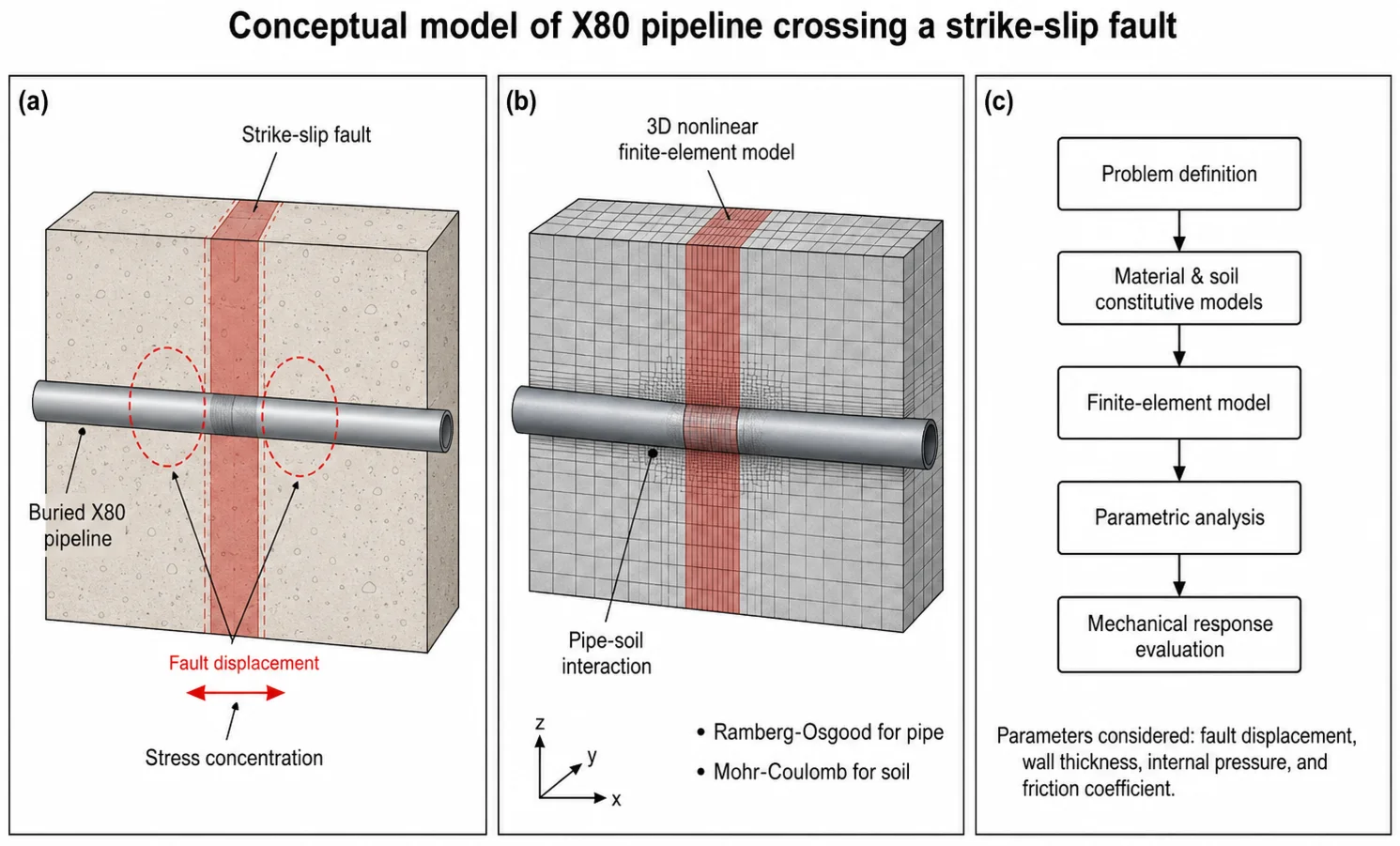
When a buried pipeline crosses an active strike-slip fault zone, the differential ground movement forces the pipeline to accommodate significant lateral displacement. As shown in Fig. 1, the fault displacement induces bending deformation in the pipeline, with stress concentration regions developing on both sides of the fault plane. To accurately simulate this complex deformation behavior, an appropriate pipe-soil interaction model must be selected.
Fig. 1Schematic diagram of buried pipeline under strike-slip fault action
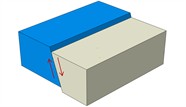
a) Normal fault
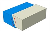
b) Reverse fault
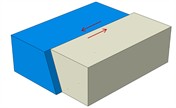
c) Strike-slip fault
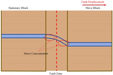
d) Effect of faulting on buried pipeline
Pipe-soil interaction model is a key tool to simulate the mechanical response of underground pipeline and surrounding soil, commonly used soil spring model, PSI cell model and nonlinear contact model as in Fig. 2, the three due to different simplification ideas and technical paths, there are differences in accuracy and efficiency.
The soil spring model equates the soil as an array of discrete springs, characterizes the soil properties by the spring stiffness, does not need a solid soil model, and transforms the surrounding soil into a 3D elastic-plastic spring by adjusting the parameters to simulate the soil properties and fault displacement effects. However, it does not take into account the deformation characteristics of the soil body under load, and it is difficult to accurately describe the details of the pipe-soil contact surface response.
The PSI unit model relies on the ABAQUS platform, with one side of the unit discretized to characterize the soil action domain, and the other side of the unit is co-nodal with the pipe wall, which eliminates the process of contact interface presetting and simplifies the contact process by integrating the interface contact effect with the soil body's intrinsic response. The computational efficiency is high, but it is difficult to accurately describe the local instability of the pipe wall, and it is also unable to completely characterize the stress gradient distribution of irregular cross-section members.
Fig. 2Pipe-soil interaction model
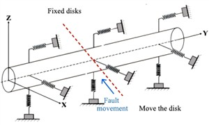
a) Pipeline-earth spring
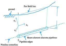
b) PSI unit
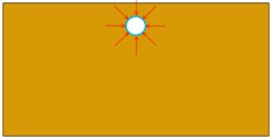
c) Pipe-soil interaction
The nonlinear contact model is based on discrete pipe units and surrounding rocks to construct a full-domain coupling system, which comprehensively takes into account the geometric nonlinearity of the pipe, the large deformation of the structure and the nonlinearity of the contact interface. The commonly used surface contact algorithm can accurately reproduce the relative slip and contact stress transfer during fault misalignment, with non-invasive constraints (allowable detachment) in the normal direction and frictional slip penalty function in the tangential direction. Compared with the traditional model, it can more realistically reflect the dynamic coupling mechanism, improve the accuracy of stress field solution, and provide reliable support for pipeline deformation damage analysis.
2.2. Pipe failure criteria
The failure of buried pipelines can be classified into two basic categories: the stress-controlled failure criterion is determined by monitoring the maximum stress state of the pipe body, and the loss of load-bearing capacity is determined when the working stress on the pipe body breaks through the threshold of plastic deformation of the material (i.e., the fourth yield criterion); and the strain-controlled failure criterion focuses on monitoring the deformation response, and when the value of the axial tensile or compressive strains reaches the threshold of the critical plastic strains, it is destructive deformation of the structure is recognized.
2.2.1. Stress-based failure criteria
The fourth strength theory, also known as the von Mises yield criterion or maximum distortion energy criterion, is adopted in this study as it provides accurate prediction of yielding under multiaxial stress states typical of buried pipelines subjected to combined internal pressure, soil loading, and fault displacement. According to Von Mises stress yielding criterion, pipe yielding occurs as the pipe reaches a certain value of the maximum equivalent stress can be determined, the expression is:
where , , are pipe principal stress in three directions / MPa; is pipeline yield stress / MPa; is permissible stress of pipeline/MPa; is design coefficient; is design coefficient of welding seam.
According to GB50251-2015 [26] Design Code for Gas Transmission Pipeline Engineering’, the strength design coefficient of 0.9 corresponds to Class II pipeline design requirements applicable to cross-country transmission lines. The weld joint coefficient of 1.0 indicates that all circumferential and longitudinal welds undergo 100 % radiographic inspection, ensuring weld strength equivalent to the parent material. Given that the project adopts X80 grade pipeline steel (yield limit 541 MPa), the allowable stress is calculated as: 0.9×1.0×541 = 486.9 MPa. When the peak von Mises stress of the pipe body exceeds 486.9 MPa, the pipeline is determined to have reached the bearing limit state.
2.2.2. Strain-based failure criteria
Strain-based design is widely adopted for assessing pipeline integrity under large deformation conditions. Table 1 summarizes the tensile strain limits specified in major international codes. CSA Z662-2011, DNV-OS-F101, and ASCE-2005 commonly adopt 2 %-2.5 % as the critical tensile strain threshold. The Chinese standard GB/T 50470-2017 [27] employs a calculation-based approach, where the allowable strain is determined through fracture mechanics analysis considering weld defect geometry, material toughness, and hoop stress ratio.
In this study, the 2 % tensile strain limit is adopted as the design criterion, consistent with international practice. This design limit differs from the ultimate strain capacity ( 3 % for X80): the former provides a conservative engineering threshold, while the latter represents material failure capacity.
Table 1Pipeline tensile strain design guidelines [5]
Code or guideline | Strain limit (%) |
Canadian Standards Association CSAZ662-03-2011 | 2.5 |
Classification Society DNVOS-F101 | Cumulative plastic strain may exceed 2.0 |
American Society of Civil Engineers ASCA-2005 | 2.0 |
GB/T 50470-2017 | Calculation based |
3. Finite element modeling of buried pipelines across traveling slip faults
To better reveal the mechanical response characteristics of X80 pipeline under the action of strike-slip faults, the technical approach adopted in this paper is as follows Fig. 3.
Fig. 3Technology Roadmap

3.1. Pipeline material structural modeling
X80 grade steel was selected for this study due to its widespread application in modern high-pressure, long-distance gas transmission pipelines, including the China-Russia Eastern Route Pipeline. Compared to lower grades (X42-X70), X80 offers superior yield strength (≥ 555 MPa) and tensile strength (≥ 625 MPa), enabling higher operating pressures and reduced wall thickness requirements. Its balanced combination of strength, toughness, and weldability makes it the preferred material for cross-fault pipeline applications.
3.1.1. Ramberg-Osgood intrinsic curve
In the geological tectonic zone, with the fault, along with the cumulative growth of the amount of dislocation, the buried pipeline in the adjacent area of the fracture zone to form a bimodal deformation concentration area. When the stress on the pipeline exceeds the yield strength, the material constitutive behavior enters the stage of strain intensification, and its stress-strain evolution path significantly deviates from the linear elastic constitutive framework. According to the relevant regulations of GB/T50470-2017 “Seismic Code for Oil and Gas Transmission Pipeline Line Engineering Technology” in China. It is recommended to give priority to the use of triple folding model for the pipe system crossing the section of active fracture zone for the constitutive model or Ramberg-Osgood constitutive model:
where is yield offset; is pipe yield stress; is strain hardening index; is modulus of elasticity of the steel pipe; is strain; is stress.
In the absence of measured data for , , and , the corresponding values may be determined based on Table 2.
Table 2Parameters of Ramberg-Osgood equation
Steel grade | (MPa) | ||
X80 | 530 | 0.981 | 20.12 |
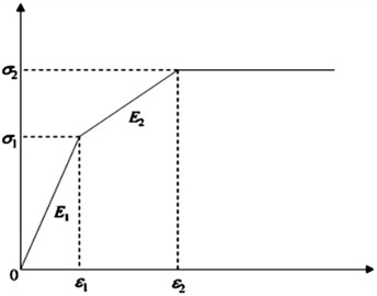
3.1.2. Trifold intrinsic model
At the beginning of displacement loading, the pipe structure is in a small deformation stage, conforming to linear elasticity with stable elastic modulus and proportional stress-strain relationship. When soil misalignment displacement exceeds the critical value, the pipe enters the plastic development stage, where the growth rate of plastic strain increases significantly and the structure continues to accumulate irreversible deformation until failure. For the trilinear model, and correspond to the yield point (elastic limit), while and characterize the ultimate/failure threshold. represents the elastic modulus in the elastic stage, and corresponds to the stiffness in the elastic-plastic stage. The 2 % design strain limit provides a safety margin below the material’s 3 % () ultimate strain capacity.
The pipeline parameters used in this study are for X80 steel pipe with elastic modulus 2.1×10⁵ MPa, Poisson’s ratio 0.3, and density 7850 kg/m3. For the trilinear model, X80 parameters are: 0.0026, 2.1×10⁵ MPa, = 541 MPa, 0.030, = 2061 MPa, = 597 MPa.
Table 3Performance parameters of commonly used steel materials
Steel grade | Elastic region | Plastic zone | ||||
Strain | Modulus (MPa) | Stress (MPa) | Strain | Modulus (MPa) | Stress (MPa) | |
X80 | 0.0026 | 2.1×10⁵ | 541 | 0.030 | 2061 | 597 |
Fig. 4The Ramberg-Osgood principal configuration
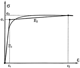
Fig. 5Triple folded line of sight eigen fig
3.2. Soil modeling of strike-slip faults
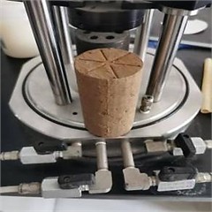
Soil samples from the China-Russia Eastern Route project site were analyzed to obtain relevant soil material parameters through in-situ testing (Fig.6). The soil type is classified as silty clay from the sliding zone. Laboratory testing included triaxial compression tests and direct shear tests following Chinese standards. The specific parameters measured are shown in the Table 4 and Table 5. A parametric study on soil stiffness was conducted with E ranging from 15 to 60 MPa, covering typical conditions along the pipeline route from soft clays to dense gravels. Results showed that softer soils reduce pipe stress by allowing greater pipe-soil relative displacement, while stiffer soils increase stress concentration.
Table 4Relevant parameters of soil
Soil | Density / kg/m3 | Modulus of elasticity / MPa | Poisson’s ratio | Cohesion / KPa | Angle of internal friction / ° |
Sliding zone | 1870 | 32.5 | 0.3 | 30.4 | 27.6 |
Table 5Relevant parameters of spring
Equivalent soil spring stiffness | Axial / KN/m/m | Lateral / KN/m/m | Vertical upward / KN/m/m | Vertical downward / KN/m/m |
22937 | 2304 | 5159 | 13546 | |
Note: Equivalent spring stiffness calculated based on ASCE Guidelines for burial depth 1.5 m and pipe diameter 1422 mm, provided for reference comparison with soil spring models. | ||||
Fig. 6Soil material parameters. Photo by the author Pengcheng Pei
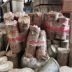
a) Soil samples collected on site
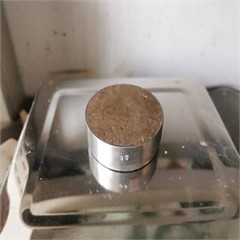
b) Ring knife method
c) Soil triaxial experiment
3.3. Finite element modeling
The three-dimensional nonlinear finite element model was developed using ABAQUS software. The geotechnical medium employs C3D8R type three-dimensional continuum elements (8-node linear brick with reduced integration, 3 degrees of freedom per node), which are higher-order elements with geometric nonlinear analysis capability that can accurately simulate large-strain conditions and meet the mechanical response requirements of this study. The structural parameters of the pipe system refer to the engineering parameters of the China-Russia cross-country X80 gas pipeline, with nominal diameter 1422 mm and design wall thickness 25.7 mm, giving / = 55.3 which is within the thin-shell regime (/ > 20). The S4R shell element is selected for the pipe body (4-node doubly curved shell with reduced integration, 6 degrees of freedom per node), which can effectively characterize the mechanical behavior of the pipe under complex loads including axial tension, shear, and torsion.
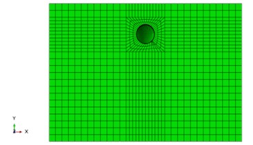
Based on preliminary analysis, the fault influence zone is mainly distributed within 40 m on both sides of the fault trace. Combined with the requirements of the “Technical Specification for Seismic Resistance of Oil and Gas Transmission Pipeline Engineering” that the X-axial soil computational domain needs to be ≥ 60 D, the final geotechnical computational domain is set to 100 m (L)×20 m (W)×10 m (H). A sensitivity analysis confirmed that 10 m depth is adequate, with stress influence extending only to approximately 6 m depth for the displacement range studied, and negligible displacement (< 0.1 % of fault displacement) observed at domain boundaries. The mesh consists of approximately 45,000 elements for the pipe and 180,000 elements for the soil. Mesh encryption is implemented in the circumferential region of the pipe wall and fault contact zone, with mesh transition ratio controlled within 1:3 to ensure accurate capture of stress concentration effects.
The Ramberg-Osgood constitutive model is adopted for X80 steel behavior, while Mohr-Coulomb plasticity is used for soil modeling. Pipeline self-weight is included in the analysis. Boundary conditions include: fixed base (all degrees of freedom constrained), symmetric lateral boundaries, and fault displacement applied as uniform lateral displacement on the bottom boundary within 40 m of the fault plane. This simplified uniform displacement model is a standard engineering approximation used in many published studies. The geometric topology and mesh system of the established finite element model are shown in Fig. 7-8.
The following key assumptions are made in this study: (1) Quasi-static fault movement – justified for slow fault creep scenarios; dynamic analysis would be required for seismic loading. (2) Homogeneous soil properties – the soil parameters represent average conditions; parametric study on soil stiffness addresses spatial variability. (3) Uniform fault displacement distribution – this is a standard engineering approximation; more realistic displacement profiles would shift peak locations but preserve the bimodal pattern. (4) Temperature effects neglected - the analysis focuses on mechanical loading; thermal expansion effects should be considered in future work. (5) Shell element adequacy – for / = 55.3, shell theory is appropriate for global response, though local buckling may require solid elements or sub-modeling for detailed analysis.
Fig. 7Soil finite element model
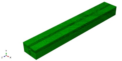
Fig. 8Left view of soil body
3.4. Validation of finite element model for buried pipeline crossing strike-slip fault
To verify the accuracy of the finite element model for pipelines subjected to fault action, a comparative validation was conducted. Asghar Vatani Oskouei (2019) [28] performed systematic experimental investigations on buried pipeline systems in strike-slip fault zones, revealing the failure mechanisms of pipelines under fault displacement loading. In this study, a three-dimensional finite element model was established using identical parameters, and the axial strain of the pipeline was extracted. The numerical simulation results were compared with existing experimental data to validate the accuracy of the finite element model.
Fig. 9Validation of pipeline axial strain: numerical vs. experimental results
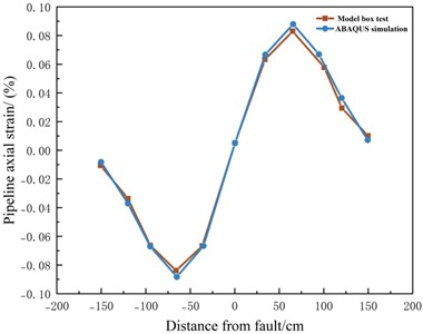
A numerical model was developed based on the experimental configuration, and the calculated pipeline axial strains were compared with the measured experimental data. The comparison results are shown in Fig. 9 The numerical predictions are slightly higher than the experimental observations; however, the overall discrepancy remains small. The results demonstrate good agreement between the numerical solution and experimental data, thereby validating the effectiveness of the modeling approach adopted in this study.
4. Analysis of pipeline mechanical response law under the action of strike-slip faults
4.1. Effect of fault misalignment volume
Under geological hazards such as fault dislocation, the pipe-soil interaction is significantly intensified, resulting in stress concentration, plastic deformation, and non-uniform response characteristics in local regions of buried pipelines [29-33]. With the increase of fault displacement, the soil-pipe interaction intensifies, as evidenced by the significant increase in pipeline stress and strain shown in Figs. 12-16. Under the soil constraint, the pipeline in the neighboring region of the fault undergoes significant plastic deformation, while the pipeline in the distal region shows only a small displacement response due to the synergistic movement with the soil body. Under different stagger conditions, the interaction between the soil and the pipe triggers the pipe deformation to show a gradient increasing trend, and the specific stress distribution characteristics as shown in the numerical simulation part of the results are shown in the following Figs. 10, 11.
Fig. 10Displacement of fault layer 0.5 m (Stress unit MPa)
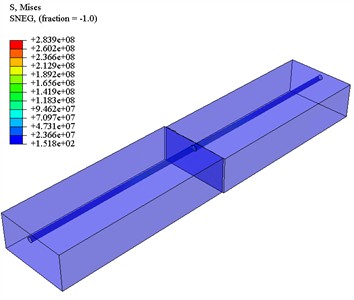
Fig. 11Fault displacement of 2.5 m (Stress unit MPa)
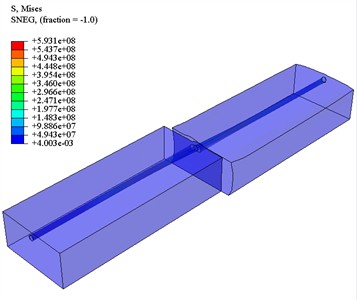
Fig.12 shows the von Mises stress distribution along the pipeline path, with the origin of the coordinate system located at the center of the fault plane ( 0). A characteristic bimodal distribution is observed: the von Mises stress reaches minimum value at approximately 0 m, reaches maximum values at approximately +20 m and –20 m (on opposite sides of the fault plane), with secondary peaks at approximately +10 m and –10 m. This “M-shaped” distribution is characteristic of strike-slip fault loading.
By comparing the strain responses under different fault displacements, it is found that the von Mises stress is positively correlated with fault displacement, but the rate of stress increase diminishes with larger displacements due to material yielding. Specifically, increasing displacement from 0.5 m to 1.0 m approximately doubles the stress, but increasing from 2.0 m to 2.5 m yields only a 15 % stress increase as the material enters the plastic regime. This nonlinear behavior has important implications for design, indicating that protective measures become increasingly important as displacement approaches the elastic limit.
Fig. 12Mises stress of pipeline under different fault misalignment
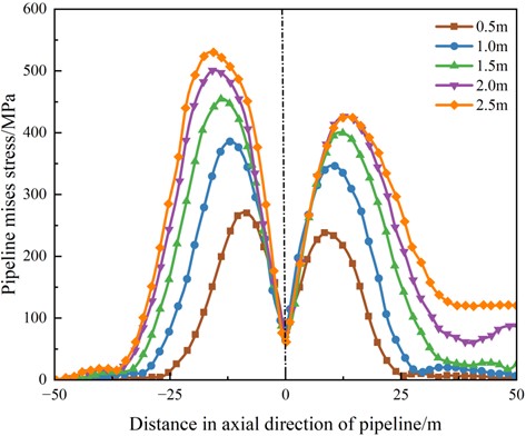
Fig. 13Mises stress cloud of pipeline under different fault misalignment amount
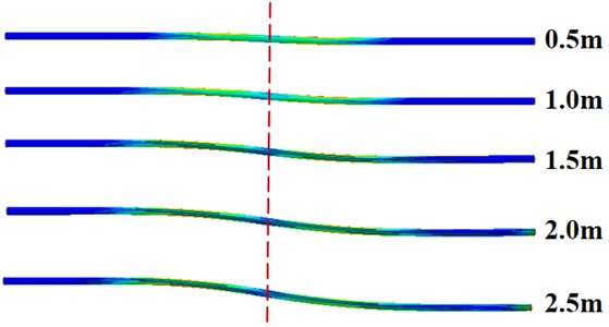
Fig. 14 shows the axial stress distribution along the pipeline path, the origin of the coordinate system is located in the center of the fracture zone axis 0. The axial stress reaches the minimum value along the pipe diameter of –20 m, and reaches the maximum value along the pipe diameter of about 10 m, and its distribution shows quasi-sinusoidal fluctuation, showing a decrease and then an increase. By comparing the stress response under different fault displacements, it is found that the axial stress is positively correlated with the displacement, but the increase of stress shows a decreasing trend with the increase of displacement. For example, when the fault displacement amount of 1.0 m than the fault displacement amount of 0.5 m increment is about 1 times, but the fault displacement amount of 2.5 m value and the fault displacement amount of 2.0 m value is approximately equal.
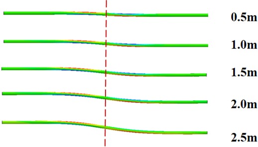
Fig. 15 demonstrates the characteristics of axial strain distribution along the pipeline path, with the origin of the coordinate system located at the center of the fracture zone axis at 0. The axial strain reaches a minimum value at about –20 m along the pipe diameter and a maximum value at about 10 m along the pipe diameter, and its distribution shows a quasi-sinusoidal fluctuation with a decrease and then an increase. By comparing the strain response under different fault misalignments, it is found that the axial strain is positively correlated with the displacement, but the increase of the strain shows a decreasing trend with the increase of the displacement. For example, when the fault displacement is 1.0 m, the increase is about one times than that of 0.5 m, but at 2.0 m, the increase is only about 10 % compared with that of 1.5 m fault misalignment. The strain cloud is shown in Fig. 16.
Fig. 14Axial stress of pipe under different dislocation amount
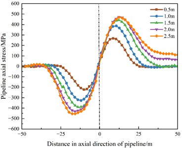
Fig. 15Axial strain of pipeline under different dislocations
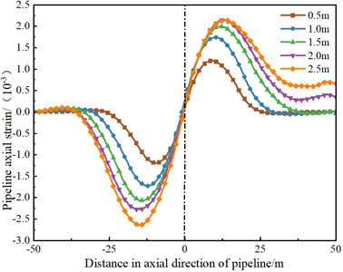
It should be noted that under strike-slip fault loading, the pipeline primarily undergoes lateral bending, resulting in axial stress as the dominant component. The hoop stress is mainly attributed to internal pressure and is incorporated in the von Mises equivalent stress calculation. Therefore, axial strain is presented as the primary deformation indicator in this study.
Both stress-based and strain-based failure criteria were evaluated. For stress-based assessment, the allowable von Mises stress is 486.9 MPa (yield strength 541 MPa × design factor 0.9). For strain-based assessment, the critical tensile strain limit is 2 % per CSA Z662 and DNV-OS-F101 guidelines. At the maximum analyzed fault displacement of 2.5 m with baseline parameters (wall thickness 25.7 mm), the peak von Mises stress reached approximately 520 MPa (exceeding the allowable stress by 6.8 %, indicating localized yielding has occurred), while the maximum axial tensile strain was 0.225 % (well within the 2 % limit with a substantial safety margin). These results indicate that for the analyzed conditions, the stress-based criterion governs pipeline failure, while the strain-based criterion maintains a significant safety margin. Increasing wall thickness is recommended to reduce stress concentration in high-risk fault zones.
Fig. 16Axial strain of pipeline with different fault displacements
4.2. Influence of wall thickness
Fig. 17 demonstrates the axial maximum tensile strain under different wall thicknesses as affected by fault displacement. The results show a clear linear relationship with distinct parallel trends for different thicknesses. The axial maximum tensile strain becomes progressively smaller with increasing wall thickness. For example, at 2.5 m fault displacement, the pipe with 18.4 mm wall thickness exhibits approximately twice the tensile strain compared to the 32.1 mm wall thickness pipe. This demonstrates that increasing wall thickness from 18.4 mm to 32.1 mm reduces maximum tensile strain by approximately 50 %.
Fig. 17Axial strain of pipe with different wall thicknesses
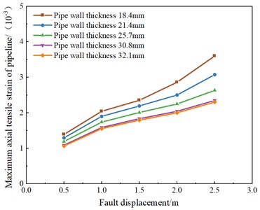
Fig. 18Mises along axis of the pipe for different wall thicknesses
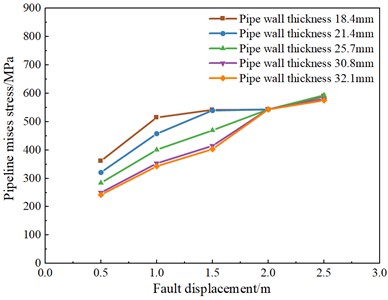
Fig. 18 shows the maximum axial von Mises stresses under different wall thicknesses. When fault displacement is less than 2 m, the curves show linear parallel trends. At 2 m displacement, all pipes reach yield strength (~ 541 MPa), hence similar stress values regardless of thickness, after which growth slows as the material enters the plastic phase. For example, at 1.5 m fault displacement, the pipe with 18.4 mm wall thickness exhibits approximately twice the Mises stress compared to the 32.1 mm wall thickness pipe. The pipe wall thickness has less influence in the plastic phase.
4.3. Effect of pipe pressure
Fig. 19 demonstrates the effect of axial maximum tensile strain on fault misalignment at different pipe pressures, where the -axis represents fault misalignment and the -axis represents the change in axial maximum tensile strain. The axial maximum tensile strain reaches the minimum value around 0.5 m of fault misalignment and the axial maximum tensile strain reaches the maximum value around 2.5 m of fault misalignment. It can be found in the fault misalignment amount is small, increase the pipe pressure for the pipe can effectively resist the outside fault misalignment, but when the fault misalignment amount is too large, the pipe pressure for a long time on the fault resistance is small, at this time by the fault misalignment for the dominant.
Fig. 19Axial strain of pipeline under different pipe pressures
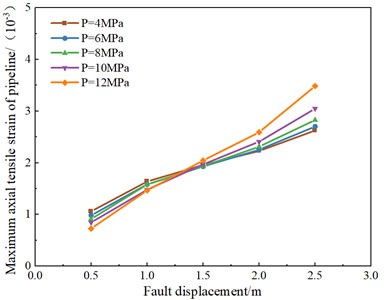
Fig. 20Mises along axis of the pipe under different pipe pressures
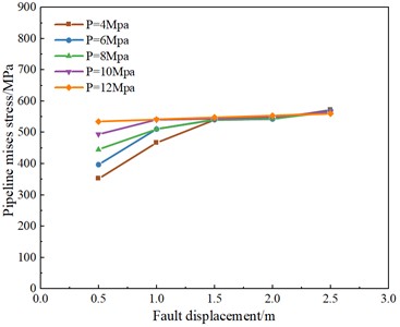
Fig. 20 shows the influence of Mises stress under different pipe pressures by fault misalignment, where the -axis indicates the fault misalignment and the -axis indicates the change of Mises stress. the Mises stress has a tendency to intersect the curves around the fault misalignment of 1.5-2.5 m, and then the stress grows less because the pipe has already reached the yield strength and enters the plastic phase.
4.4. Effect of pipe-soil friction coefficient
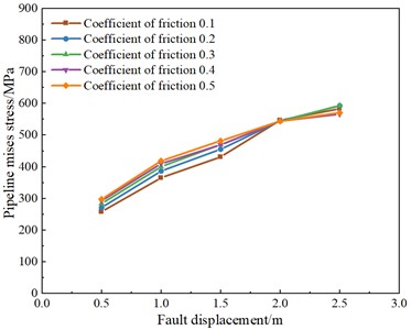
Fig. 21 shows the influence of axial maximum tensile strain under different friction coefficients by the amount of fault misalignment, where the x-axis represents the amount of fault misalignment and the y-axis represents the axial maximum tensile strain. It can be found that with the increase of fault misalignment, its axial maximum tensile strain also increases, and the whole shows a linear parallel, and its friction coefficient does not have much influence on the axial maximum tensile strain.
As shown in Fig. 22, the -axis represents the fault misalignment and the -axis represents the Mises stress change, which is linearly parallel when the fault misalignment is less than 2.0 m. The larger the friction coefficient is, the larger the Mises stress is, and the left and right curves intersect at the misalignment of 2 m. At this time, the stress of the pipeline reaches the yield strength of the pipeline, and the pipeline enters into the plastic state afterwards. In the elastic deformation stage, the friction coefficient is too high will increase the Mises stress slightly, but into the plastic stage after the effect tends to stabilize.
Fig. 21Axial strain of the pipe under different friction
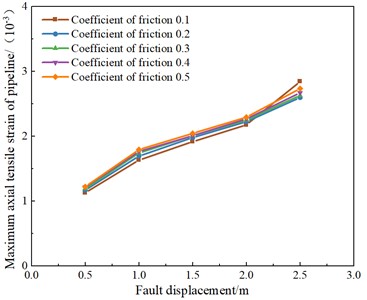
Fig. 22Mises stress along axis of the pipe under different friction
4.5. Design recommendations
Based on the parametric analysis results, the following design recommendations are provided for cross-fault buried pipelines:
1) Wall Thickness Selection: For expected fault displacements up to 1.5 m, minimum wall thickness of 25.7 mm is recommended. For displacements up to 2.0 m, wall thickness should be increased to at least 28 mm. For displacements exceeding 2.0 m, additional protective measures such as flexible joints should be implemented regardless of wall thickness.
2) Flexible Joint Installation: Flexible joints should be installed at approximately ±15-20 m from the fault plane, corresponding to the locations of peak stress concentration.
3) Monitoring Requirements: Real-time strain monitoring should be implemented in the fault-crossing section, with alert thresholds set at 1.5 % strain for inspection and 1.8 % for emergency response.
4) Operational Pressure: During periods of elevated seismic risk, operating pressure should be reduced where possible to increase the pipeline's displacement tolerance.
5. Conclusions
This study systematically investigate the mechanical response of X80 buried pipelines under strike-slip fault action. The following conclusions are drawn:
1) Fault displacement is the core parameter controlling pipeline mechanical response. With increasing fault displacement, pipeline stress and strain increase significantly but with diminishing increments as the material enters the plastic regime. The von Mises stress exhibits a characteristic bimodal distribution, with maximum values occurring at approximately ±20 m from the fault plane and secondary peaks at ±10 m.
2) Wall thickness is an important parameter affecting pipeline stress and strain. Increasing pipe wall thickness from 18.4 mm to 32.1 mm reduces axial strain by approximately 50 % and significantly decreases von Mises stress in the elastic regime. For cross-fault pipeline design, increasing wall thickness is an effective method to resist fault displacement effects.
3) Internal pressure and pipe-soil friction coefficient are key parameters affecting pipeline response when fault displacement is below approximately 2 m. Increasing pipe pressure can enhance deformation resistance within this displacement range. When fault displacement exceeds 2 m, fault movement becomes the dominant factor and these parameters have limited influence.
The significance of this study lies in providing quantitative guidelines for wall thickness selection and protective measure implementation for cross-fault pipeline design, directly supporting the safe operation of major energy transmission infrastructure.
Future research directions include: (1) dynamic analysis for seismic loading scenarios with appropriate damping; (2) investigation of lower grade steels (X42-X70) with different strain hardening characteristics; (3) field validation of numerical predictions; (4) development of more realistic fault displacement distribution models; (5) consideration of thermal expansion effects and flexibility provisions in buried piping system modeling.
References
-
S. Huang, Y. Lyu, H. Sha, and L. Xiu, “Seismic performance assessment of unsaturated soil slope in different groundwater levels,” Landslides, Vol. 18, No. 8, pp. 2813–2833, Apr. 2021, https://doi.org/10.1007/s10346-021-01674-w
-
S. Huang and C. Liu, “A computational framework for fluid-structure interaction with applications on stability evaluation of breakwater under combined tsunami-earthquake activity,” Computer-Aided Civil and Infrastructure Engineering, Vol. 38, No. 3, pp. 325–352, 2023, https://doi.org/10.1111/mice.12880
-
S. Huang, R. Tao, and R. Wang, “One simplified method for seismic stability analysis of an unsaturated slope considering seismic amplification effect,” Geological Journal, Vol. 58, No. 6, pp. 2388–2402, May 2023, https://doi.org/10.1002/gj.4769
-
P. Pei et al., “Deformation and failure mechanism of overlying soil layers under strike-slip faulting,” (in Chinese), The Chinese Journal of Geological Hazard and Control, Vol. 35, No. 6, pp. 115–127, 2024, https://doi.org/10.16031/j.cnki.issn.1003-8035.202306029
-
P. Pei et al., “Investigating the mechanism of X80 pipeline failure under landslide impact,” Vibroengineering Procedia, Vol. 58, pp. 46–52, May 2025, https://doi.org/10.21595/vp.2024.24306
-
H. E. Demirci, S. Bhattacharya, D. Karamitros, and N. Alexander, “Experimental and numerical modelling of buried pipelines crossing reverse faults,” Soil Dynamics and Earthquake Engineering, Vol. 114, pp. 198–214, Nov. 2018, https://doi.org/10.1016/j.soildyn.2018.06.013
-
H. E. Demirci, M. Karaman, and S. Bhattacharya, “Behaviour of buried continuous pipelines crossing strike-slip faults: Experimental and numerical study,” Journal of Natural Gas Science and Engineering, Vol. 92, p. 103980, Aug. 2021, https://doi.org/10.1016/j.jngse.2021.103980
-
V. E. Melissianos, G. P. Korakitis, C. J. Gantes, and G. D. Bouckovalas, “Numerical evaluation of the effectiveness of flexible joints in buried pipelines subjected to strike-slip fault rupture,” Soil Dynamics and Earthquake Engineering, Vol. 90, pp. 395–410, Nov. 2016, https://doi.org/10.1016/j.soildyn.2016.09.012
-
V. E. Melissianos, D. Vamvatsikos, and C. J. Gantes, “Performance-based assessment of protection measures for buried pipes at strike-slip fault crossings,” Soil Dynamics and Earthquake Engineering, Vol. 101, pp. 1–11, Oct. 2017, https://doi.org/10.1016/j.soildyn.2017.07.004
-
G. Banushi, N. Squeglia, and K. Thiele, “Innovative analysis of a buried operating pipeline subjected to strike-slip fault movement,” Soil Dynamics and Earthquake Engineering, Vol. 107, pp. 234–249, Apr. 2018, https://doi.org/10.1016/j.soildyn.2018.01.015
-
S. Visage et al., “Evolution of off-fault deformation of strike-slip fault in a sand-box experiment,” SSRN Electronic Journal, Jan. 2022, https://doi.org/10.2139/ssrn.4181532
-
H. F. Jahromi, F. Jafarzadeh, and M. S. Zakaria, “Experimental study of burial depth effect on embedded pipe deformations in sandy slopes under dynamic landsliding,” Soil Dynamics and Earthquake Engineering, Vol. 114, pp. 281–297, Nov. 2018, https://doi.org/10.1016/j.soildyn.2018.06.038
-
C. Pany, “Investigation of circular, elliptical and obround shaped vessels by finite element method (FEM) analysis under internal pressure loading,” Journal of Scientific Technology and Engineering Research, Vol. 3, No. 1, pp. 24–31, 2022, https://doi.org/10.53525/jster.1079858
-
C. Pany, “Cylindrical shell pressure vessel profile variation footprint in strain comparison of test data with numerical analysis,” Liquid and Gaseous Energy Resources, Vol. 1, No. 2, pp. 91–101, Dec. 2021, https://doi.org/10.21595/lger.2021.22163
-
C. Pany and G. V. Rao, “Large amplitude free vibrations of a uniform spring-hinged beam,” Journal of Sound and Vibration, Vol. 271, No. 3-5, pp. 1163–1169, Apr. 2004, https://doi.org/10.1016/s0022-460x(03)00572-8
-
H.-N. Wu, S.-L. Shen, J. Yang, and A. Zhou, “Soil-tunnel interaction modelling for shield tunnels considering shearing dislocation in longitudinal joints,” Tunnelling and Underground Space Technology, Vol. 78, pp. 168–177, Aug. 2018, https://doi.org/10.1016/j.tust.2018.04.009
-
L. Chen, “Numerical simulation study of surface deformation during a slip fault earthquake,” Journal of Shijiazhuang University of Economics, 2020.
-
Z. Liu, “Failure analysis of buried hydrogen pipelines under strike-slip fault action,” (in Chinese), Pressure Vessel Technology, Vol. 37, No. 8, pp. 52–58, 2020, https://doi.org/10.3969/j.issn.1001-4837.2020.08.009
-
Y. Wang, “Study on the mechanical properties of urban underground natural gas pipelines under the influence of strike-slip faults,” (in Chinese), Journal of North China University of Science and Technology (Natural Science Edition), 2021, https://doi.org/10.27108/d.cnki.ghelu.2021.000523
-
K. Wu, Y. Chen, and Y. Wang, “Influence of oblique slip faults on the mechanical properties of buried natural gas pipelines,” (in Chinese), Pipeline Technology and Equipment, No. 1, pp. 30–34, 2022.
-
C. Zhang et al., “Distribution pattern of creep displacement along tunnels crossing fault zones,” Journal of Central South University, Vol. 27, No. 10, pp. 2849–2863, 2020.
-
X. Zhang, “Seismic damage patterns and hinge misalignment parameters of tunnels crossing reverse strike-slip faults,” (in Chinese), Anhui University of Science and Technology, 2024.
-
Y. Liu, “Study on the mechanical behavior of high-strain subsea pipelines under strike-slip faults,” (in Chinese), China University of Petroleum (Beijing), 2023.
-
B.-L. Gan, D.-M. Zhang, Z.-K. Huang, F.-Y. Zheng, R. Zhu, and W. Zhang, “Ontology-driven knowledge graph for decision-making in resilience enhancement of underground structures: Framework and application,” Tunnelling and Underground Space Technology, Vol. 163, p. 106739, 2025, https://doi.org/10.1016/j.tust.2025.106739
-
M. Tao, X. Li, F. Alam, Y. Yan, and T. Chau, “Unveiling the impact of AI technological anxiety on the marketers’ intention to adopt generative AI,” (in ng), Journal of Global Information Management, Vol. 33, No. 1, pp. 1–22, Mar. 2025, https://doi.org/10.4018/jgim.372177
-
“Design specifications for gas pipeline engineering,” (in Chinese), China Planning Press, Beijing, GB 50251-2015, 2015.
-
“Seismic technical specifications for oil and gas pipeline route engineering,” (in Chinese), China Planning Press, Beijing, GB/T 50470-2017, 2017.
-
A. Vatani Oskouei, A. Tamjidi, and P. Pourshabani, “Effects of burial depth in the behavior of buried steel pipelines subjected to strike-slip fault,” Soil Dynamics and Earthquake Engineering, Vol. 123, pp. 252–264, 2019, https://doi.org/10.1016/j.soildyn.2019.04.031
-
S. Huang and C. Liu, “Dynamic behavior analysis of bridge pier under impact of dam-break flood in different directions,” Natural Hazards, Vol. 120, No. 3, pp. 2705–2730, Dec. 2023, https://doi.org/10.1007/s11069-023-06301-6
-
H. Shuai, C. Liu, and K. Goda, “Applicability of smooth particle hydrodynamics method to large sliding deformation of saturated slopes under earthquake action,” Chinese Journal of Geotechnical Engineering, Vol. 45, No. 2, pp. 336–344, 2023.
-
X. Zhang, S. Huang, and B. Gao, “Full-waveform CNN-transformer neural network for regional coseismic landslide susceptibility modeling: A case study of the 2022 Luding earthquake, China,” Engineering Geology, Vol. 362, p. 108520, Feb. 2026, https://doi.org/10.1016/j.enggeo.2025.108520
-
S. Huang, L. Zhang, and D. Li, “Research on simpliffied evaluation method for soil-rock mixed slope stability under dam-break flood impact,” Bulletin of Engineering Geology and the Environment, Vol. 84, No. 1, p. 46, Jan. 2025, https://doi.org/10.1007/s10064-024-04055-4
-
X. Zhang, S. Huang, B. Gao, and H. Qian, “Intelligent risk assessment of co-seismic landslide susceptibility using multi-directional seismic ground motion parameters,” Georisk: Assessment and Management of Risk for Engineered Systems and Geohazards, pp. 1–24, Oct. 2025, https://doi.org/10.1080/17499518.2025.2567480
About this article

This work is financially supported by research grants from the Science and Technology Innovation Program of Xiongan New Area (Grant No. 2025XAGG0056), National Natural Science Foundation of China (Grant No. 42577234), National Natural Science Foundation of China (Grant No. 51708516), and the National Key Research and Development Program of China (2022YFC3070103).
The datasets generated during and/or analyzed during the current study are available from the corresponding author on reasonable request.
Shuai Huang: conceptualization, methodology, software, formal analysis, funding acquisition, writing - original draft. Xinyue Zhang: data curation, validation, writing-original draft, writing-review and editing. Zhigang Tao: software, resources. Zhonghao Xiong: investigation, visualization. Junbiao He: resources, supervision, writing-review and editing. Pengcheng Pei: project administration, resources. Tingting Liu: validation, data curation. Jingwei Liu: formal analysis, investigation, visualization, methodology. Liwei Xiu: software, validation, data curation.
The authors declare that they have no conflict of interest.

