Abstract
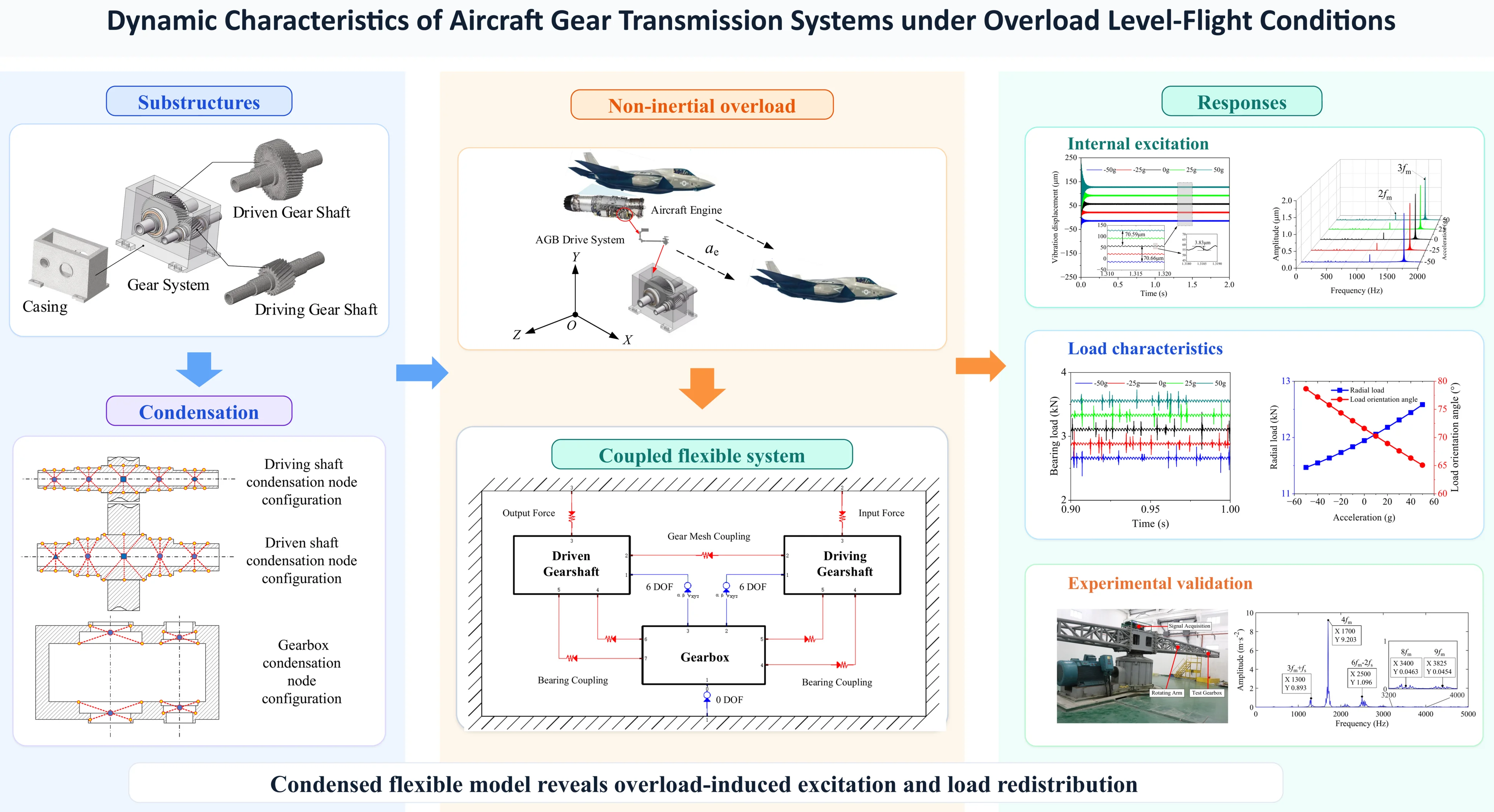
As a crucial component in aircraft power transmission, gear transmission systems are subjected to time-varying additional inertial loads in a non-inertial environment during aircraft maneuvers. Current dynamic analyses of these systems mostly depend on the inertial coordinate system, which assumes the gearbox is fixed to the ground and ignores the extra effects of base motion. Notably, existing models often use a rigid-flexible coupling approach – treating only key components like shafts as flexible while assuming others such as casings and gear teeth as rigid – which may deviate from the actual dynamic behavior of gear transmissions under maneuvering conditions. To address this limitation, this study establishes a full-flexible coupled multibody dynamics model for gear transmissions under overload level-flight maneuvers. By varying maneuvering acceleration magnitudes, the mechanisms by which maneuvering acceleration affects internal excitation and force characteristics in the system were explored. Results show that maneuvering acceleration induces shaft deformation, causing time-varying fluctuations in the center distance between meshing gears. This further leads to changes in meshing stiffness, transmission error, and tooth backlash. Correspondingly, bearing support force, gear meshing force, and Hertzian contact dynamic stress vary with maneuvering overload-especially the bearing force aligned with the overload direction, which is significantly affected by acceleration. This finding provides a critical theoretical basis for the structural design and dynamic optimization of high-maneuverability aircraft gear transmissions.
Highlights
- A fully flexible coupled multibody dynamics model is developed for aircraft gear transmissions under overload level-flight maneuvers.
- Substructure condensation is performed for the driving shaft, driven shaft, and casing before system-level coupling.
- Additional inertial excitation induced by maneuvering overload is incorporated through a hierarchical coordinate framework.
- The predicted dominant frequency trends are validated by experimental results, supporting the reliability of the proposed dynamic model.
1. Introduction
Gear transmission systems are widely used in core power systems of aircraft due to their high-power density, strong load-bearing capacity, and precise motion transmission characteristics [1]-[5]. Due to the complexity of internal excitations such as time-varying meshing stiffness, backlash, and transmission errors, coupled with long-term service under extreme conditions such as high-speed and heavy loads, gear systems exhibit significant nonlinear vibration characteristics and cause prominent dynamic problems. In severe cases, this can lead to gear failure, system malfunction, and ultimately affect the reliability of the entire system [6-8]. Notably, international aviation giants such as Sikorsky and Boeing have continuously increased their research and development investment in transmission systems, focusing on three core technological areas: high-speed operational stability, lightweight design, and vibration and noise control [9]. This reflects increasing industry requirements for dynamic stability, structural reliability, and acoustic performance of transmission systems. Therefore, investigating the dynamic characteristics of aviation gear transmission systems is essential for enhancing the technical performance and safe operation level of aviation equipment.
Regarding dynamic modeling methodologies for gear transmission systems, Wang et al. [10] established a fully coupled bending-torsional-lateral-pendular model and a bending-torsion coupled model for two-stage helical gear transmission systems, considering shaft flexibility. By comparing the effects of these two models on the system’s vibrational characteristics, their research findings demonstrate that lateral and pendular motions cannot be ignored in the precise vibration analysis of helical gear pairs. Yuan et al. [11] established a full-degree-of-freedom model for helical gear transmission systems using Timoshenko beam elements. Dynamic response results indicate that: Manufacturing errors induce sidebands in the vibration response spectrum; under light-load conditions, sidebands dominate the spectrum, while increasing torque enhances the prominence of meshing frequency and its harmonics relative to the side-bands. Li et al. [12] proposed a nonlinear dynamics model for spur gear pairs incorporating time-varying backlash, multi-state meshing and contact ratio. This model established nine safety domains to quantify system stability levels, enabling safety-basin-based analysis of bifurcation effects on operational security.
Beyond dynamic modeling methodologies, internal excitation parameters stand out as key factors influencing the dynamic response of gear systems and have received considerable scholarly attention. Core internal excitations in gear systems primarily encompass time-varying mesh stiffness, meshing damping, transmission error, and backlash. Current mathematical representations show relative consensus for meshing damping and backlash: meshing damping is predominantly modeled via Coulomb damping theory [13], while backlash is universally characterized by piecewise nonlinear displacement functions [14]. In contrast, precise modeling of mesh stiffness and transmission error remains an active research frontier. Cooley et al. [15] compared the averaged slope method and local deflection slope method for calculating mesh stiffness, investigating their respective applicability in static and dynamic contexts. Wei et al. [16] developed an analytical mesh stiffness model for helical gears incorporating axial deflection, enhancing computational efficiency through sliced tooth contact analysis. Duan et al. [17] investigated time-varying transmission error under varying load, rotational speed, and housing mass conditions, considering the effects of flexible shafts and housing, with experimental validation. For refined contact behavior characterization, Abruzzo et al. [18] demonstrated viable integration of FEA-derived stiffness/error data into lumped-parameter models, achieving strong correlation between nonlinear response predictions and experimental validation; the study concurrently elucidated torque and speed dependencies on dynamic transmission error through experimental investigation. Benaicha et al. [19] created a system-level flexible multibody gear contact model incorporating Lagrange formulation, face-to-face contact detection, tooth compliance, and profile deviations. Through combined consideration of global and local deformations, this model achieves smoother peak-to-peak transitions behavior in predicted stiffness and transmission error.
Current dynamic analyses of gear transmission systems predominantly rely on a fixed coordinate system, assuming the gearbox is rigidly mounted to the aircraft fuselage while neglecting additional effects from base motion. However, modern aircraft face increasingly stringent performance demands requiring frequent overload flight maneuvers such as steep turns, zoom climb, and roll escape. These maneuvers subject transmission components to significant inertial excitation loads, triggering strong nonlinear dynamic coupling between aircraft spatial motions and elastic deformations. Under maneuver overloads, generalized inertia forces acting on critical transmission members can induce flexible-body deformations, thereby modifying gear system operational characteristics. Considering its significance, research on non-inertial frame gear dynamics has witnessed a notable surge in recent years.
Yi et al. [20] established a gear-rotor system dynamics model for roll, pitch, and yaw maneuver environments using Lagrange energy method, investigating transient time-frequency responses under maneuvering parameters and mass imbalance excitation. Qiu et al. [21] developed a planetary gear dynamics model during base pitch motion, employing Runge-Kutta methods to solve system responses and identify spectral characteristics. Wei et al. [22] investigated the load-sharing characteristics, contact dynamic stress, and bending dynamic stress of planetary gear transmission systems under aircraft maneuvers including level flight, rolling, and looping. The results indicate that maneuvering flight conditions exacerbate load imbalance in planetary gear trains and elevate dynamic stress levels. Yue et al. [23] constructed a non-inertial frame finite element dynamics model incorporating gear-rotor-bearing assemblies with Timoshenko beam elements, identifying natural frequencies and critical speeds via Campbell diagrams while systematically analyzing complex influences of translational/rotational carrier motion on inherent characteristics and dynamic responses. Ye et al. [24] validated their theoretical model through experimental tests and further investigated the dynamic behavior of gear transmission systems during aircraft hover maneuvers. Specifically, they analyzed the effects of additional inertial forces and gyroscopic moments induced by airframe maneuvering motion on the dynamic responses of critical system components including casings, bearings and shafts under non-inertial frames.
Existing studies predominantly employ lumped-mass or rigid-flexible coupling methodologies, which fail to model all critical transmission components as flexible bodies, neglect real-time dynamic coupling between substructures, and inadequately address the effects of flexible deformations and component interactions. To overcome these limitations, this work establishes a fully-coupled multibody dynamics model encompassing flexible shaft assemblies, deformable gear pairs, deformable bearings, and flexible casing based on multi-flexible-body dynamics modeling. Furthermore, we derive analytical expressions for additional inertial excitations induced by overload level flight and integrate them into the model, systematically investigating dynamic responses and critical component load characteristics under varying overload values. This research provides crucial theoretical underpinnings for high-accuracy dynamic design and performance assessment of gear transmission systems under extreme overload maneuvering conditions.
2. Dynamic modeling of gear transmission systems under overload level flight maneuvers
2.1. Substructure condensation model
To establish a fully flexible multibody dynamics model for the gear transmission system, the system is first divided into three substructures: the driving gear shaft, the driven gear shaft, and the casing. Each substructure is discretized and a component-level finite element model is established, as illustrated in Fig. 1.
Fig. 1Substructure division
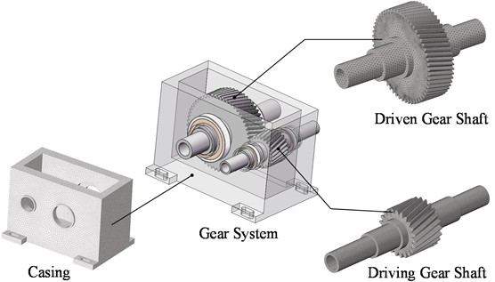
Such dense meshing inevitably leads to an excessive number of degrees of freedom (DOFs), resulting in inefficient calculation and incompatibility with system dynamics analysis requirements. Therefore, Guyan condensation [25-27] is adopted to reduce the original finite element model, which greatly lowers the calculation cost while ensuring the necessary accuracy.
The governing equations of motion for each substructure are expressed as Eq. (1):
where denotes the node displacement vector, represents the node load vector, and , , stand for the mass matrix, damping matrix, and stiffness matrix respectively. Based on substructure characteristics, DOFs are partitioned into master DOFs and slave DOFs . The master DOFs correspond to external nodes, while the slave DOFs correspond to internal nodes, and the dimension of is much smaller than that of .
Derived from static equilibrium conditions, the partitioned stiffness matrix equation is expressed as Eq. (2):
where, and are formulated as the stiffness matrices corresponding to the DOFs of master and slave nodes, respectively. is designated as the coupling stiffness matrix. The external load applied to the master node is denoted by . Since no external load is applied to the slave nodes, the load vector is set to a zero vector.
Derived from the second equation of Eq. (2), the displacement of slave nodes can be solved as:
The displacement vector can be expressed in terms of the master node displacement vector as:
Under the static equilibrium assumption neglecting the inertia of slave nodes, Eq. (4) is substituted into Eq. (1) and premultiplied by :
Thus, from Eq. (5), the condensed substructure dynamic equations are obtained as follows:
To achieve further reduction in DOFs, condensation nodes are established at substructure coupling interfaces. Kinematic constraints between these condensation nodes and the master nodes are enforced using the Multi-point Constraint (MPC) method [28]:
where denotes the DOFs of the condensation node, represents the weight coefficient of the master node , and indicates the number of coupled master nodes. Functionally, condensation nodes are categorized into five types, as illustrated in Fig. 2:
1) Gear Mesh Condensation Node, located at the center of the gear bore;
2) Power Input Condensation Node, located at the center of input positions in the driving gear shaft core;
3) Power Output Condensation Node, located at the center of output positions in the driven gear shaft core;
4) Bearing Coupling Condensation Node, located at the center of the corresponding shaft hole and the casing bearing bore;
5) Geometric Feature Condensation Node, located at the shaft segments with high slenderness ratios or complex local geometry.
Through Eq. (7), coupling relations between condensation nodes and master nodes are established. This allows the model parameters to be represented by condensation nodes in dynamic modeling, significantly reducing the DOFs while maintaining sufficient precision, thereby enhancing computational efficiency in multibody dynamics.
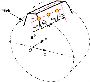
To account for the effects of gear body flexibility on transmission performance, a flexible gear model is constructed using the tooth surface condensation method to accurately simulate tooth bending deformation, shear deformation, and other effects. Three condensation nodes are equidistantly arranged along the tooth width direction at the intersection line between the tooth width mid-plane and the pitch cylinder surface for each tooth of the helical gear. As shown in Fig. 3, a local Cartesian coordinate system is established on the helical gear end face, with its -axis coinciding with the tooth symmetry axis and its -axis aligned with the shaft bore centroidal axis. The angular displacement between adjacent condensation nodes within a single tooth is thus defined as:
where: is the face width, is the lead. For a right-hand helical gear, the angle between any tooth’s condensation node and the -axis is given by Eq. (9):
where denotes the tooth index (1, 2…, ), is the index of the condensation node within the same tooth (1, 2, 3), and represents the number of teeth. The Cartesian coordinates of any condensation node are calculated from the angular position as:
where represents the pitch circle radius. The coordinates of gear tooth condensation nodes are then used to generate the condensation node set through computational programming, enabling full-flexibility modeling of the gear system.
Fig. 2Condensation nodes configuration
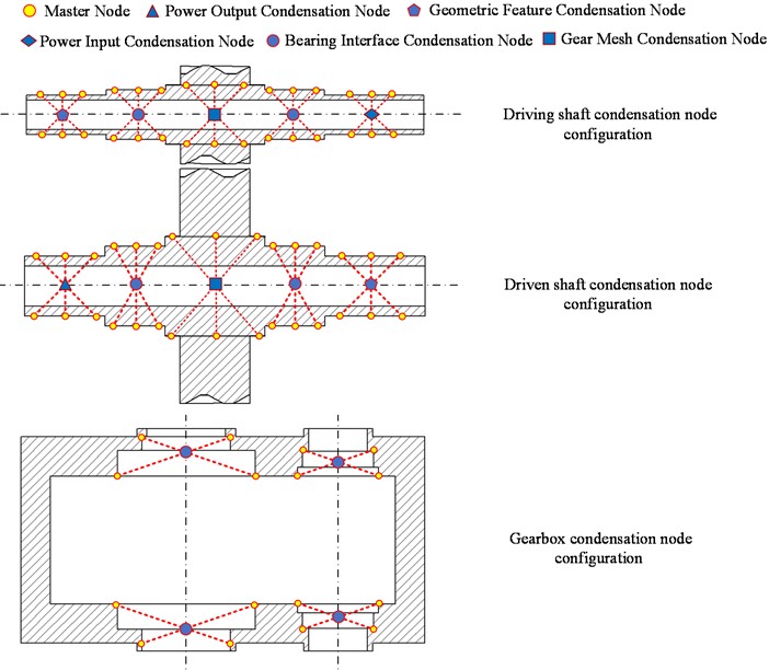
Fig. 3Condensation nodes of helical gear
2.2. Substructure coupling relationships
The gear transmission system dynamically couples the shaft substructures through gear mesh elements connected to gear mesh condensation nodes. Specifically, this interaction is characterized by equivalent spring-damper elements along the line of action (LoA), where the kinematic constraints are enforced. To quantify the displacement projection mechanism, the time-varying mesh vector projects the multi-degree-of-freedom displacement of the gear pair onto the LoA direction. This projection relationship is explicitly defined by the following vector expression:
where: and are respectively defined as the base circle radii of the driving and driven gears, represents the tooth pressure angle, denotes the position angle of the driving gear, and is the base circle helix angle.
Taking transmission error and backlash into account, the relative deformation along the normal direction of the meshing line is corrected to:
where, denotes the gear mesh condensation node vector, the formulations of and are defined per reference [29].
Consequently, the normal dynamic meshing force is governed by:
where, and are defined as the time-varying meshing stiffness and meshing damping coefficient of the gear pair, respectively.
For helical gears, is decomposed into three-dimensional force components, which include the tangential force , radial force , and axial force , as shown in Eq. (14):
The coupling relationship is depicted in Fig. 4.
Fig. 4The gear meshing element
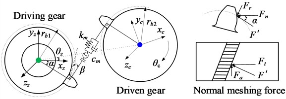
The bearing support element is implemented to establish the coupling relationship between the shafting system and the casing, as illustrated in Fig. 5.
Fig. 5The bearing support element
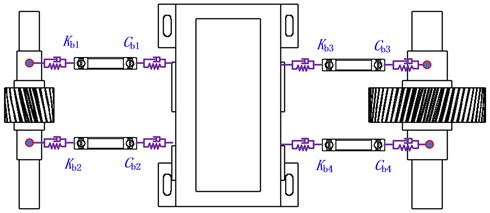
To characterize its dynamic behavior, the six-degree-of-freedom bearing support stiffness matrix and damping matrix must be established. The reaction force equation for bearing is expressed as:
where, the force vector , the velocity vector , and displacement vector of bearing are defined as follows:
2.3. Additional excitation during overload level flight
To characterize the kinematic behavior of aircraft gear transmission systems under maneuvering overload conditions, a hierarchical coordinate framework is established as depicted in Fig. 6. The Earth inertial coordinate system serves as the global reference basis. The gearbox-body coordinate system is affixed to the aircraft airframe, maintaining continuous coincidence with the aircraft body axes in both position and orientation throughout all maneuvering states. Local coordinate systems and define the instantaneous spatial poses of the driving and driven gear shafts respectively.
Based on the theory of flexible multibody system dynamics, the position vector of an arbitrary point on flexible substructures in the inertial coordinate system is expressed by Eq. (17):
where: denotes the position vector of the origin of the gearbox-body coordinate system with respect to the inertial coordinate system ; represents the rotation transformation matrix from to ; designates the position vector of point p in the undeformed state within , coinciding with point ; indicates the additional displacement vector from to due to elastic deformation.
Fig. 6Kinematic analysis
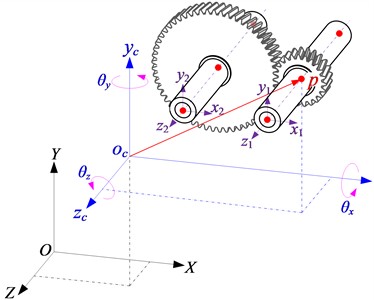
a) Node position vector
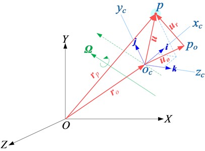
b) Hierarchical coordinate framework
By differentiating Eq. (17), the absolute velocity vector of point in the inertial coordinate system is obtained:
where: denotes the translational velocity of the origin in the gearbox-body coordinate system ; represents the angular velocity vector of ; corresponds to the rotational convective velocity, where is the position vector of in ; defines the relative velocity due to elastic deformation.
Differentiating Eq. (18) gives acceleration vector of point on the flexible body in the inertial coordinate system :
where: is defined as the translational acceleration of the origin in the gearbox-body coordinate system ; denotes the tangential acceleration due to angular acceleration; represents the centripetal acceleration; is the Coriolis acceleration; defines the relative acceleration induced by elastic deformation.
According to d’Alembert’s principle, the expression for the additional inertial force at any node in the gear transmission system is given by:
where is the mass of node , and is the absolute acceleration vector of node in the inertial system , which determined by Eq. (18). Three-dimensional spatial maneuvers can be decomposed into a combination of level flight, circular motion, and rolling motion [30]. Under variable-speed level flight condition ( 0), the additional inertial acceleration comprises solely translational acceleration and the relative acceleration of elastic deformation . Considering gravitational force , the resultant force components at node are expressed as Eq. (21):
where, is defined as the gravitational acceleration, and represents the vertically upward unit vector.
2.4. System coupling dynamic model
Considering gear transmission systems operating under overload level flight conditions, the complete coupled dynamic equations are established in the inertial coordinate system . This model integrates substructure condensation matrices, time-varying gear mesh characteristics, bearing support stiffness and maneuver flight effects, expressed as:
In the left-side dynamic terms, , , and are denoted as the condensed mass, damping, and stiffness matrices of the gear shaft substructure; , , and are represented as the condensed matrices of the casing substructure. and are defined as the time-varying meshing damping matrix and time-varying meshing stiffness matrix of the gear pair, respectively. , , and are denoted as the corresponding block matrices of the bearing stiffness, respectively; and are defined as the modified velocity and displacement vectors with transmission error coupling.
In the right-side excitation terms, is denoted as the driving/driven torque vector, in which the non-zero terms correspond to the input and output nodes. is defined as the overall system gravity vector, and represents the overall system additional inertial force, whose nodal component values are shown in Eq. (21).
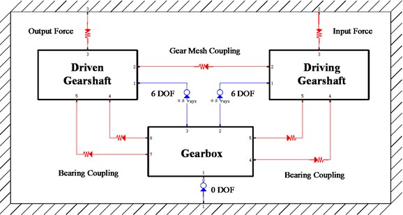
The gear shaft systems are coupled through gear meshing elements, and the shaft systems are coupled with the casing through bearing elements, forming a coupled dynamic model of a fully flexible gear-shaft-bearing-casing multibody system. The coupling topological relationships are illustrated in Fig. 7.
Fig. 7Coupled topology of fully flexible gear multibody dynamic model
3. Internal excitation dynamics in aircraft transmissions under overload level flight maneuvers
Focused on a specific transmission stage within an aeroengine accessory gearbox (AGB), this study investigates its dynamic characteristics under different maneuvering overload conditions during level flight, with the system operating at rated conditions of 1500 r/min input speed and 300 kW input power. As shown in Fig. 8, without loss of generality, the maneuvering overload acceleration is applied tangentially to the radial gear mesh force direction, and relevant parameters are provided in Table 1.
Fig. 8Overload level flight maneuver schematic diagram
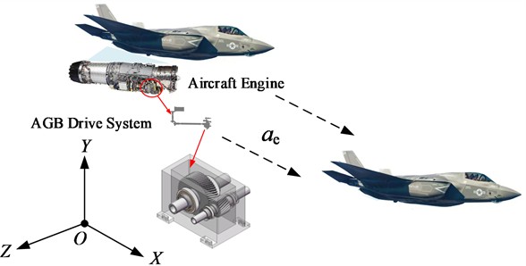
Table 1Basic parameters of helical gear pair
Name | Symbol | Driving / Driven shaft |
Modulus (mm) | 4.25 | |
Pressure angle (°) | 25 | |
Number of teeth | 23/57 | |
Helix angle (°) | 15 | |
Tooth width (mm) | 70 | |
Shift coefficient | 0 | |
Gear shaft mass (kg) | / | 5.6/28.7 |
The vibration response of the power input node at the driving shaft under overload level flight conditions (–50 g to +50 g) is presented to exhibit typical dynamic characteristics. It should be noted that the ±50 g range represents theoretical boundaries designed to magnify the system's sensitivity to inertial loads for parametric analysis, rather than practical aircraft operational envelopes. Extending the acceleration limits theoretically allows for a clearer elucidation of the dynamic response trends.
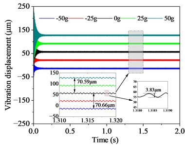
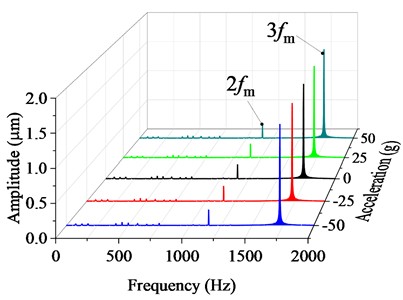
Time-domain analysis (Fig. 9(a)) shows that the mean value of vibration displacement is symmetric about the static condition (0 g), and a quasi-linear offset is exhibited with the overload acceleration. The maximum dynamic offset is found to reach 70.59 μm, with a 128 % increase achieved compared to the static reference value, while the fluctuation range of vibration displacement is maintained stably within ±3.83 μm. Frequency-domain analysis (Fig. 9(b)) further reveals that the dominant vibration energy is concentrated on the second order harmonic (1150 Hz) and third order harmonic (1725 Hz) of the meshing frequency, while the fundamental meshing frequency (575 Hz) is suppressed.
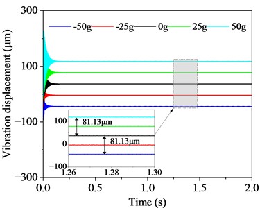
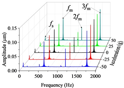
The distribution characteristics of the time-domain displacement of the driven shaft (Fig. 10(a)) are shown to be identical to those of the driving shaft, yet the vibration amplitude is significantly increased. The mean value of the maximum offset under 50 g is found to reach 81.13 μm, exceeding that of the driving shaft by 14.9 %. The frequency-domain spectrum (Fig. 10(b)) is shown to reveal the coexistence of the shaft rotational frequency (25 Hz), the fundamental meshing frequency (575 Hz), and their second-/third order harmonics (1150 Hz/1725 Hz), exhibiting broader spectral energy distribution than the driving shaft. Comparative analysis demonstrates that maneuvering overload substantially modifies the mean displacement characteristics of the shafts. The larger mass of the driven shaft generates stronger inertial forces, resulting in more severe deformation offsets. Spectral analysis demonstrates that although the overload acceleration does not alter the spectral distribution, higher-order harmonics become the predominant frequencies in the vibrational displacement response.
Fig. 9Vibration displacement at power input location of driving gear shaft
a) Time domain
b) Frequency domain
Fig. 10Vibration displacement at power output location of driven gear shaft
a) Time domain
b) Frequency domain
It is revealed by these findings that the fluctuation of the center distance is the key mechanism through which the dynamic response of the system is affected by the overload inertial force. Quantification of this mechanism requires characterizing the center-distance offset evolution against overload acceleration profiles.
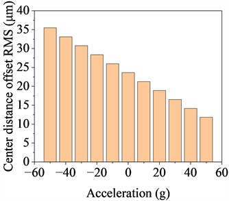
The root-mean-square (RMS) center distance offset is shown in Fig. 11. Under static condition (0 g), meshing separation forces induce bidirectional elastic deformation of the gear shafts, yielding a baseline offset of 23.63 μm. With maneuvering overload application, two response regimes emerge: From –50 g to 0 g, the large gear (driven gear) experiences co-directional inertial centrifugal force and radial meshing force ( direction), while force opposition occurs at the small gear (driving gear). The asymmetric shaft deformation induced by inertial force disparity between gears drives a peak center distance offset of 35.47 μm at –50 g. From 0 g to 50 g, force vector reversal creates counter-directional alignment at the large gear but co-directional at the small gear (+ direction). This inertial-mesh force cancellation, amplified by mass asymmetry, generates a linear reduction in offset to 11.81 μm at 50 g. The 66.7 % reduction in offset amplitude from 35.47 μm to 11.81 μm demonstrates that inertial forces dominate center-distance fluctuations.
Fig. 11Centre distance offset of gear transmission system
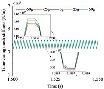
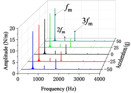
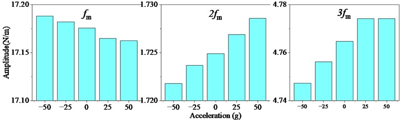
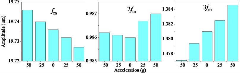
The above analysis confirms that maneuvering acceleration loads alter the operating center distance of the gear pair, directly modifying its meshing stiffness characteristics. As acceleration shifts from –50 g to 50 g, the time varying center distance progressively decreases, extending the effective contact length. This geometric change increases the contact ratio, enabling more tooth pairs to participate in load sharing. Consequently, time domain analysis (Fig. 12(a)) demonstrates that the mean time varying meshing stiffness increases from 3.66×10⁹ N/m to 3.68×10⁹ N/m. Frequency domain reveals (Fig. 12(b)) that the fundamental mesh frequency (575 Hz) identified as the dominant stiffness excitation component, which exhibits amplitude attenuation under rising acceleration loads. Conversely, the second harmonic 2 (1150 Hz) and third harmonic 3 (1725 Hz) are progressively increased with the change of maneuvering overload (Fig. 12(c)), indicating that maneuvering-induced inertial forces suppresses the fundamental meshing frequency, driving spectral energy redistribution from the main frequency to higher-order harmonics.
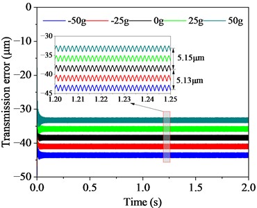
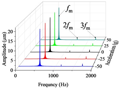
Under level flight dynamic accelerations, dynamic center distance fluctuations within the gear pair induce kinematic deviation of the actual contact point from the theoretical mesh position, constituting the dominant excitation mechanism for transmission error (TE). As quantified in Fig. 13(a), at –50 g maneuvering overload acceleration, TE is found to increase by an average of 5.13 μm compared to the aircraft stationary condition. As the maneuvering acceleration changes from –50 g to 50 g, the absolute value of transmission error is reduced. At 50 g, TE registers a 5.15 μm decrease versus stationary condition. Spectral decomposition of TE time-series data (Fig. 13(b)) reveals three dominant components: the fundamental meshing frequency (575 Hz), second harmonic 2 (1150 Hz), and third harmonic 3 (1725 Hz). While maintains persistent spectral dominance, its amplitude undergoes progressive attenuation across the –50 g→ 50 g acceleration envelope. Concurrently, harmonic energies intensify, showcasing vibrational energy migration from the fundamental meshing frequency to higher-order harmonics (Fig. 13(c)).
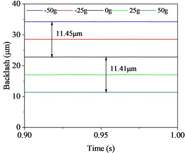
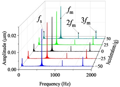
Analysis of Fig. 14(a) confirms that progressive reduction in center distance offset intensifies gear flank engagement, resulting in backlash reduction from 34.3 μm at –50 g to 11.3 μm at 50 g. The resultant magnitude reduction reaches 66.7 %, validating overload-induced suppression of tooth clearance. Spectral decomposition in Fig. 14(b) reveals three dominant components: shaft rotational frequency (25 Hz), fundamental meshing frequency (575 Hz) and associated harmonics. Crucially, maintains persistent spectral dominance while preserving identical amplitude and distribution characteristics across all overload conditions. Spectral analysis confirms that maneuvering acceleration negligibly affects the spectral characteristics and amplitude magnitudes in backlash measurements.
Fig. 12Time varying gear mesh stiffness
a) Time domain
b) Frequency domain
c) Amplitude trend
Fig. 13Time varying gear transmission error
a) Time domain
b) Frequency domain
c)
Fig. 14Time varying backlash
a) Time domain
b) Frequency domain
4. Effects of differential overload maneuvers on load characteristics
Analysis establishes that aircraft base motion-induced inertial loads represent external operating conditions for the transmission system, while input/output torque profiles define internal loading constraints. This dual-condition loading model enables the investigation of overload level-flight maneuvers on the dynamic load transfer properties of shaft-bearing systems. By solving the fully coupled dynamic equations of the gear transmission system accounting for the additional effects of maneuvering flight, the dynamic bearing loads at each bearing node under different level-flight acceleration are obtained. All load vectors are transformed into the inertial coordinate system , with bearing positions illustrated in Fig. 15.
Fig. 15Bearing mounting locations and designations
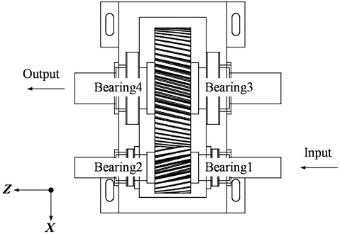
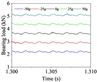
Fig. 16(a-d) quantify bearing loads dynamics at Bearing 1 (power-input end) of the driving shaft, while Fig. 16(e-h) characterize Bearing 2 (non-input end). Results indicate that the bearing loads of the driving shaft exhibit nonlinear growth with varying accelerations from –50 g to 50 g. The -direction component aligned with the maneuver direction exhibits dominant response: for Bearing 1, the -direction load increases from 2.28 kN at –50 g to 5.17 kN at 50 g, marking 127 % growth (Fig. 16(a)); for Bearing 2, the -direction load linearly increases from 5.58 kN to 8.27 kN, increasing by 48 % (Fig. 16(e)).
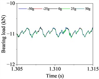
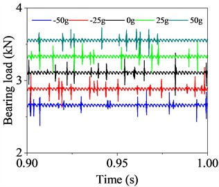
-direction bearing loads show negligible sensitivity to acceleration changes, as confirmed by Fig. 16(b) and 16(f). Conversely, -direction load exhibit acceleration-dependent increases (Fig. 16(c) and 16(g)), albeit with significantly lower growth rates versus -direction.
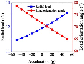
Fig. 16Load characteristics of driving shaft bearings
a) Bearing 1 -direction load
b) Bearing 1 -direction load
c) Bearing 1 -direction load
d) Bearing 1 radial load
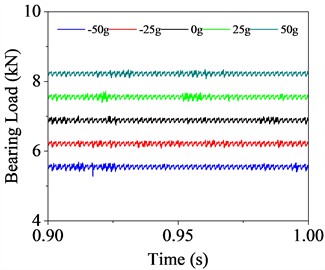
e) Bearing 2 -direction load
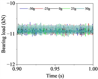
f) Bearing 2 -direction load
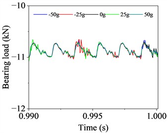
g) Bearing 2 -direction load
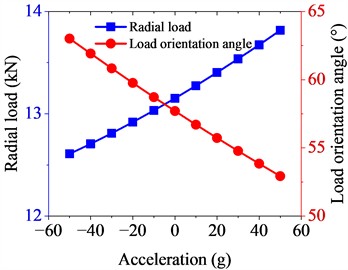
h) Bearing 2 radial load
Resultant radial load analysis reveals that the radial load on Bearing 1 increases from 11.47 kN (–50 g) to 12.58 kN (50 g), an increase of 9.7 %, with the load orientation angle rotating clockwise from 78.64° to 65.07°, while confined to Quadrant I (Fig. 16(d)). For Bearing 2, the radial load increases from 12.61 kN (0 g) to 13.82 kN (50 g), an increase of 9.6 %, with the load orientation angle shifting from 63.01° to 52.93° in Quadrant I (Fig. 16(h)). The radial resultant load on Bearing 2 is greater compared to Bearing 1, but Bearing 1 exhibits more pronounced changes in the -direction response.
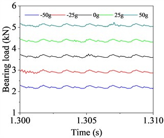
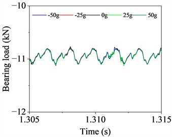
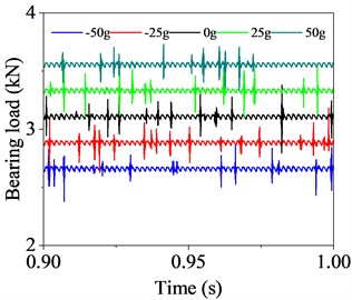
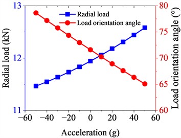
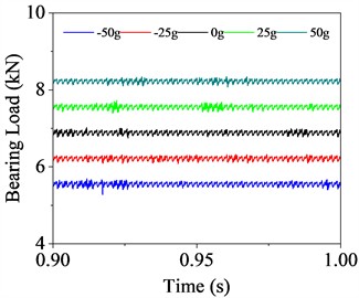
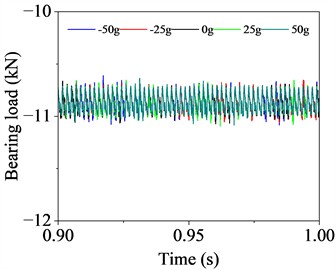
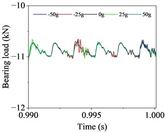
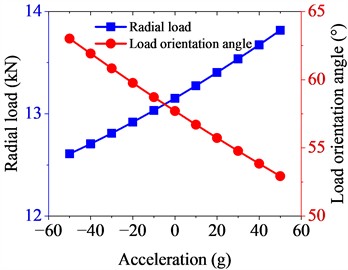
Analysis of the driven shaft bearing loads (Fig. 17) confirms that acceleration variations from –50 g to 50 g induce significant load redistribution. At Bearing 3 (non-output end), absolute magnitude of the -direction bearing load decreases from 16.82 kN to 2.24 kN, a reduction of 86.68 %. Meanwhile, the -direction load at Bearing 4 (power-output end) changes direction, from –7.79 kN to 6.03 kN. Similar to the driving shaft, the -direction load remains unaffected by acceleration variations.
In the -direction, the absolute load at Bearing 3 decreases from 3.63 kN to 2.98 kN, a reduction of 17.91 %, and at Bearing 4, the absolute -direction load reduces from 3.12 kN to 2.47 kN, a reduction of 20.83 %. The evolution of radial resultant load shows a 41.87 % reduction at Bearing 3 from 20.23 kN to 11.76 kN, with the load orientation angle in Quadrant I, increasing from 33.13° to 78.11°. At Bearing 4, the radial load initially decreases from 13.82 kN (–50 g) to 11.23 kN (10 g), then rises again to 12.63 kN (50 g). Correspondingly, the load angle first rotates from 54.01° (–50 g) to 88.02° (10 g), then further shifts to 61.50° (50 g), consistently remaining in Quadrant I.
In conclusion, bearing loads of both driving and driven shafts undergo significant changes under maneuvering overload level flight conditions. Therefore, the influence of additional inertial loads should not be neglected in bearing selection and strength verification.
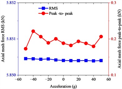
Maneuvering overload accelerations from –50 g to 50 g induce only minimal quantitative alterations in gear meshing force characteristics. As illustrated in Fig. 18, the RMS of the radial component exhibits a linear micro-reduction from 10.55 kN to 10.54 kN, representing a marginal decay of 0.015 kN and a 0.14 % decay rate. Radial peak-to-peak fluctuations remain constrained within 0.4-0.8 kN throughout the acceleration envelope.
Fig. 17Load characteristics of driven shaft bearings
a) Bearing 3 -direction load
b) Bearing 3 -direction load
c) Bearing 3 -direction load
d) Bearing 3 radial load
e) Bearing 4 -direction load
f) Bearing 4 -direction load
g) Bearing 4 z-direction load
h) Bearing 4 radial load
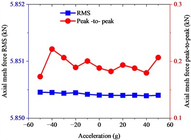
Fig. 18Gear mesh force
a) Radial force
b) Axial force
Contrastingly, the axial component RMS maintains near-invariant stability, varying between 5.850 kN and 5.852 kN with maximum deviation below 0.002 kN. Axial peak-to-peak oscillations are confined to a 0.1-0.3 kN magnitude range, showing that the axial component is barely affected by acceleration.
This confirms that maneuvering accelerations induce only micro-scale radial mean load attenuation without substantial alteration to dynamic impact characteristics (peak-to-peak signatures) or axial load-bearing stability.
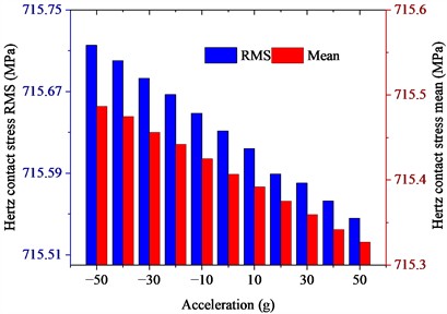
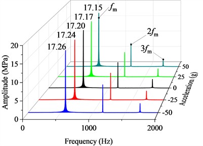
As shown in Fig. 19, quantitative analysis of the time varying gear Hertz contact stress under maneuvering accelerations (–50 g to 50 g) confirms a 0.02 % reduction in RMS values, decreasing from 715.72 MPa to 715.55 MPa, while the mean contact stress shows a 0.022 % decline , reducing from 715.49 MPa to 715.33 MPa. These minimal variations demonstrate that inertial loads negligibly alter the stress characteristics in aerospace gear contacts. Frequency-domain analysis reveals that the dominant excitation frequencies of Hertzian contact stress are the gear meshing frequency (575 Hz) and its harmonics. The fundamental meshing frequency amplitude (575 Hz) exhibits a linear reduction with variations in level-flight acceleration, decreasing from 17.26 MPa at –50 g to 17.15 MPa at 50 g.
Fig. 19Gear Hertz contact stress
a) Time domain
b) Frequency domain
The results indicate that the contact behavior at the mesh interface is strictly governed by the torque and speed. Under the rated operating conditions, the meshing force remains the primary excitation. Consequently, the incremental dynamic effects induced by maneuvering overloads are essentially overwhelmed by the main transmission load, leading to the observed stability in gear mesh forces and Hertzian contact stresses.
5. Experimental verification and discussion
While experimental validation under sustained translational maneuvering acceleration is the ideal approach, to perform an effective steady-state spectral analysis on high-frequency gear mesh vibrations, the transmission system must be maintained in a strictly constant overload state for a sufficient steady-state duration. Quantitatively, maintaining a continuous translational acceleration even for a few seconds would necessitate a long high-precision linear track and result in an extremely high terminal velocity, which exceeds the physical and safety constraints of conventional laboratory linear motion platforms. Furthermore, conventional high-g shock equipment, such as drop towers, can only generate transient accelerations lasting a few milliseconds, which is incapable of capturing the steady-state dynamic evolution required for this study.
To validate the proposed modeling methodology despite these physical constraints, a kinematic equivalence verification is conducted based on a generalized non-inertial framework. The fully flexible coupled multibody dynamics model is established upon a generalized arbitrary non-inertial reference frame. Mathematically and physically, pure translational overload represents a specific case where the base's rotational angular velocity is zero. The introduction of base rotation transitions the system into a rotating non-inertial environment. Consequently, validating the model under complex rotational conditions inherently substantiates the theoretical formulations.
As illustrated in Fig. 20(a), a large-scale constant acceleration rotating test bench is utilized to simulate maneuvering overloads. The test bench has a single-arm length of 7.8 m and is driven by a YB2 series flameproof three-phase asynchronous motor. By adjusting the arm’s rotational speed to 33.8 r/min, 47.9 r/min, and 58.6 r/min, maneuvering accelerations of 10 g, 20 g, and 30 g are generated in the -direction of the gear transmission system under test. The tested gear transmission system primarily consists of a driving motor, a gearbox, and a magnetic powder brake, as shown in Fig. 20(b). The experimental system utilizes a spur gear pair, characterized by a modulus of 2 mm and a pressure angle of 20°. The number of teeth for the driving and driven gears are 17 and 42, with corresponding tooth widths of 12 mm and 10 mm, respectively. During the test, the input speed is maintained at 1500 r/min, and the load torque is adjusted to 1.85 N·m by regulating the excitation current of the magnetic powder brake. Notably, although the specific physical parameters of the experimental setup differ from those in the numerical simulation, the setup is structurally analogous to the theoretical model, sharing an identical fundamental configuration and underlying dynamic mechanisms.
Fig. 20Test equipment
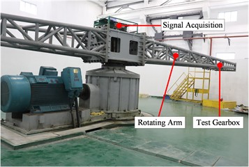
a) Acceleration rotating test equipment
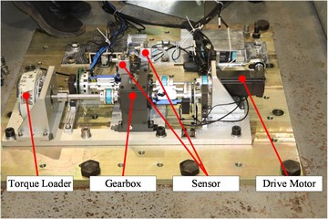
b) Test gearbox
The vibration acceleration of the system was measured using a PCB-352C03 type integrated circuit piezoelectric (ICP) accelerometer, with the sampling frequency configured at 10240 Hz. The time-domain signals and amplitude spectra under various maneuvering acceleration conditions were compared with the results derived from the theoretical model.
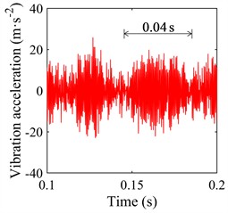
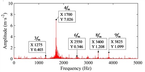
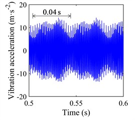
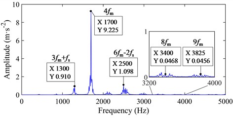
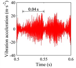
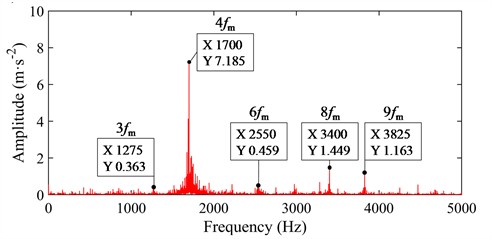
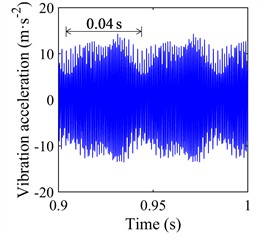
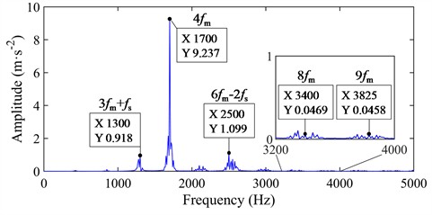
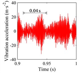
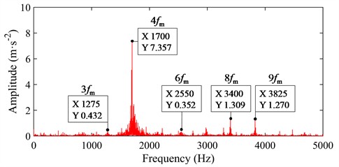
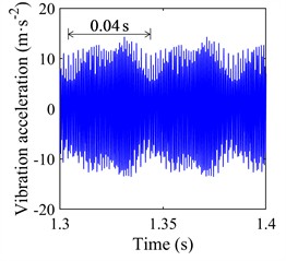
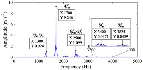
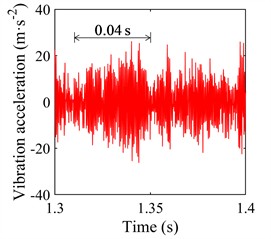
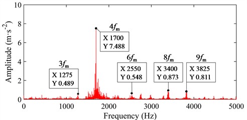
For different magnitudes of maneuvering overloads, the vibration acceleration responses and spectral characteristics in the -direction at measurement point 1 (located on the bearing housing at the input end) are illustrated in Figs. 21-24. The time-domain signals exhibit distinct periodic oscillation patterns, where the characteristic period of 0.04s corresponds to the 25 Hz shaft rotation frequency. Spectral analysis reveals that the dominant frequency of the acceleration response predicted by the theoretical model is the 4th harmonic of the mesh frequency (1700 Hz), followed by the sum of the 3rd mesh harmonic and the shaft rotation frequency, and the difference between the 6th mesh harmonic and twice the shaft rotation frequency. The distribution of characteristic frequencies in the experimental signals remains consistent with the theoretical analysis. The phenomenon where the amplitudes of the 8th and 9th harmonics in the experimental results exceed the theoretical predictions is primarily attributed to the simplifications in the model, such as bearing support stiffness and system damping. Nevertheless, the evolutionary trends of the overall spectral characteristics demonstrate consistency.
Comparative analysis of the amplitude spectra under various maneuvering acceleration conditions reveals that the amplitudes of the acceleration frequency components predicted by the theoretical model increase progressively with the maneuvering acceleration. Simultaneously, the amplitude of the dominant frequency component captured in the experimental signals also exhibits a near-linear increase as the maneuvering acceleration rises. These results demonstrate that the proposed full-flexible coupled dynamics modeling method can effectively capture the dynamic evolution trends of the gear system under maneuvering overloads. Since rotational maneuvers and translational accelerations can be described within the framework of the generalized non-inertial reference frame, the validation of the dynamic characteristics under rotational conditions further substantiates the reliability of the modeling methodology for predicting the system's dynamic responses under aircraft overload level-flight conditions.
Fig. 21Vibration acceleration under 0 g maneuvering acceleration
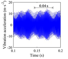
a) Theoretical time domain
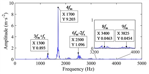
b) Theoretical frequency domain
c) Experimental time domain
d) Experimental frequency domain
Fig. 22Vibration acceleration under 10 g maneuvering acceleration
a) Theoretical time domain
b) Theoretical frequency domain
c) Experimental time domain
d) Experimental frequency domain
Fig. 23Vibration acceleration under 20 g maneuvering acceleration
a) Theoretical time domain
b) Theoretical frequency domain
c) Experimental time domain
d) Experimental frequency domain
Fig. 24Vibration acceleration under 30 g maneuvering acceleration
a) Theoretical time domain
b) Theoretical frequency domain
c) Experimental time domain
d) Experimental frequency domain
6. Conclusions
This study focuses on clarifying the dynamic response mechanism of aircraft gear transmission systems under overload level-flight conditions, based on a fully flexible coupled multibody dynamics model that integrates flexible shafts, deformable gear pairs, flexible bearings, and deformable casings. By incorporating additional inertial excitations induced by overload maneuvers and conducting systematic analysis, the regulatory effects of maneuvering acceleration on the system’s internal excitation and load characteristics are elucidated, with key conclusions as follows:
1) Maneuvering overload induces a linear variation in vibration response by causing shafts deformation. This shaft deformation further intensifies the dynamic fluctuation of center distance offset, which in turn leads to changes in time-varying mesh stiffness, transmission error, and tooth backlash. This cascade effect clarifies that the fluctuation of center distance offset acts as the immediate driver for the evolution of the gear system’s core internal excitation parameters, while shaft deformation serves as the critical precursor linking maneuvering overload to center distance offset variation.
2) Maneuvering overload alters the dynamic force characteristics of critical components, primarily manifesting in changes to bearing support forces and force angles. For the shaft-bearing system, the redistribution of inertial loads driven by maneuvering acceleration directly modifies the magnitude and direction of bearing support forces, which is consistent with the variation law of shafts deformation and center distance offset.
3) Within the –50 g to +50 g maneuvering acceleration range, the root mean square (RMS) and mean values of gear meshing force and Hertzian contact stress exhibit slight linear attenuation under maneuvering overload, while their peak-to-peak values show no significant fluctuation. This indicates that maneuvering overload has a negligible impact on the dynamic impact characteristics of gear meshing contact, and the stability of gear meshing behavior is maintained despite changes in internal excitation and bearing force.
4) Experimental validation on a rotating test bench substantiates the model’s accuracy via kinematic equivalence. The amplitude of the 4th mesh harmonic in the vibration acceleration response increases progressively with maneuvering load, aligning with the theoretical trend and confirming the methodology’s reliability for predicting gear dynamics under overload level-flight conditions.
This study provides a theoretical framework and quantitative benchmark for the dynamic reliability design of transmission systems in high-maneuverability aircraft, with findings that can guide the structural optimization and performance assessment of aircraft gear transmissions under extreme maneuvering conditions.
References
-
J. Hu, Y. Yang, N. Hu, and X. Lin, “Dynamic modeling and characteristic analysis of a helicopter main reducer for tooth crack diagnosis,” Measurement, Vol. 247, p. 116823, Apr. 2025, https://doi.org/10.1016/j.measurement.2025.116823
-
C. Peeters, W. Wang, D. Blunt, T. Verstraeten, and J. Helsen, “Fatigue crack detection in planetary gears: Insights from the HUMS2023 data challenge,” Mechanical Systems and Signal Processing, Vol. 212, p. 111292, Apr. 2024, https://doi.org/10.1016/j.ymssp.2024.111292
-
C. Yang, H. Li, S. Cao, K. Zhang, and W. Xiang, “A fast method for robust estimation of gearbox instantaneous speed,” Mechanical Systems and Signal Processing, Vol. 212, p. 111273, Apr. 2024, https://doi.org/10.1016/j.ymssp.2024.111273
-
Z. Tian et al., “Modeling of flexible bevel gear rotor systems: Modal and dynamic characterization,” Thin-Walled Structures, Vol. 197, p. 111627, Apr. 2024, https://doi.org/10.1016/j.tws.2024.111627
-
P. Magryta and K. Pietrykowski, “Failure analysis of transmission gear in aircraft opposed piston Diesel engine using FEM method,” Engineering Failure Analysis, Vol. 175, p. 109569, Jun. 2025, https://doi.org/10.1016/j.engfailanal.2025.109569
-
H. Yu et al., “Friction status monitoring for gear couplings of helicopter tail drive shaft system via friction system response driven,” Measurement, Vol. 254, p. 117836, Oct. 2025, https://doi.org/10.1016/j.measurement.2025.117836
-
C. Liu, C. Yang, Y. Zhao, J. Luo, and X. Chen, “Dynamic modeling and analysis of high-speed flexible planetary gear transmission systems,” Alexandria Engineering Journal, Vol. 80, pp. 444–464, Oct. 2023, https://doi.org/10.1016/j.aej.2023.08.079
-
M. Li, Y. Luo, L. Qu, L. Xie, and B. Zhao, “Influence of ring gear flexibility on the fatigue reliability of planetary gear systems in heavy helicopters,” Mechanism and Machine Theory, Vol. 191, p. 105520, Jan. 2024, https://doi.org/10.1016/j.mechmachtheory.2023.105520
-
Y. Zhou, H. Zhao, and Y. Liu, “An evaluative review of the VTOL technologies for unmanned and manned aerial vehicles,” Computer Communications, Vol. 149, pp. 356–369, Jan. 2020, https://doi.org/10.1016/j.comcom.2019.10.016
-
Q. Wang, Z. Li, H. Ma, and B. Wen, “Effects of different coupling models of a helical gear system on vibration characteristics,” Journal of Mechanical Science and Technology, Vol. 31, No. 5, pp. 2143–2154, May 2017, https://doi.org/10.1007/s12206-017-0410-z
-
B. Yuan, S. Chang, G. Liu, and L.-Y. Wu, “Quasi-static and dynamic behaviors of helical gear system with manufacturing errors,” Chinese Journal of Mechanical Engineering, Vol. 31, No. 1, p. 30, Apr. 2018, https://doi.org/10.1186/s10033-018-0238-1
-
Z.-F. Li, L.-Y. Zhu, S.-Q. Chen, Z.-G. Chen, and X.-F. Gou, “Study on safety characteristics of the spur gear pair considering time-varying backlash in the established multi-level safety domains,” Nonlinear Dynamics, Vol. 109, No. 3, pp. 1297–1324, May 2022, https://doi.org/10.1007/s11071-022-07467-7
-
J. Wei, P. Bai, D. Qin, T. C. Lim, P. Yang, and H. Zhang, “Study on vibration characteristics of fan shaft of geared turbofan engine with sudden imbalance caused by blade off,” Journal of Vibration and Acoustics, Vol. 140, No. 4, p. 041010, Aug. 2018, https://doi.org/10.1115/1.4039246
-
M. Pleguezuelos, M. B. Sánchez, and J. I. Pedrero, “Analytical model for meshing stiffness, load sharing, and transmission error for spur gears with profile modification under non-nominal load conditions,” Applied Mathematical Modelling, Vol. 97, pp. 344–365, Sep. 2021, https://doi.org/10.1016/j.apm.2021.03.051
-
C. G. Cooley, C. Liu, X. Dai, and R. G. Parker, “Gear tooth mesh stiffness: A comparison of calculation approaches,” Mechanism and Machine Theory, Vol. 105, pp. 540–553, Nov. 2016, https://doi.org/10.1016/j.mechmachtheory.2016.07.021
-
J. Wei et al., “A study of nonlinear excitation modeling of helical gears with Modification: Theoretical analysis and experiments,” Mechanism and Machine Theory, Vol. 128, pp. 314–335, Oct. 2018, https://doi.org/10.1016/j.mechmachtheory.2018.06.005
-
T. Duan, J. Wei, A. Zhang, Z. Xu, and T. C. Lim, “Transmission error investigation of gearbox using rigid-flexible coupling dynamic model: Theoretical analysis and experiments,” Mechanism and Machine Theory, Vol. 157, p. 104213, Mar. 2021, https://doi.org/10.1016/j.mechmachtheory.2020.104213
-
M. Abruzzo, M. Beghini, C. Santus, and S. Manconi, “Dynamic behavior of a power re-circulating gear test rig including periodic variation of mesh stiffness and static transmission error,” Mechanism and Machine Theory, Vol. 159, p. 104247, May 2021, https://doi.org/10.1016/j.mechmachtheory.2021.104247
-
Y. Benaïcha, J. Perret-Liaudet, J.-D. Beley, E. Rigaud, and F. Thouverez, “On a flexible multibody modelling approach using FE-based contact formulation for describing gear transmission error,” Mechanism and Machine Theory, Vol. 167, p. 104505, Jan. 2022, https://doi.org/10.1016/j.mechmachtheory.2021.104505
-
Y. Yi, Z. Qiu, and Q. Han, “The effect of time-periodic base angular motions upon dynamic response of asymmetric rotor systems,” Advances in Mechanical Engineering, Vol. 10, No. 3, p. 1687814018767172, Mar. 2018, https://doi.org/10.1177/1687814018767172
-
X. Qiu, Q. Han, and F. Chu, “Dynamic modeling and analysis of the planetary gear under pitching base motion,” International Journal of Mechanical Sciences, Vol. 141, pp. 31–45, Jun. 2018, https://doi.org/10.1016/j.ijmecsci.2018.03.037
-
J. Wei, D. Jiang, A. Zhang, and H. Cheng, “Dynamic stress calculation model of planetary gear transmission system under time-varying posture and its parameter influence research,” Journal of Mechanical Engineering, Vol. 57, No. 21, p. 150, Jan. 2021, https://doi.org/10.3901/jme.2021.21.150
-
Z. Yue, Z. Chen, J. Qu, and G. Yu, “Research on dynamic characteristics of gear-rotor-bearing transmission system in non-inertial system,” Journal of Vibration Engineering and Technologies, Vol. 12, No. S1, pp. 585–599, Dec. 2024, https://doi.org/10.1007/s42417-024-01434-9
-
J. Ye, J. Wei, A. Zhang, S. Chen, T. Ran, and R. Shu, “Theoretical and experimental study on the dynamic behavior of spur gear transmission system during hovering maneuver flights,” Mechanical Systems and Signal Processing, Vol. 212, p. 111296, Apr. 2024, https://doi.org/10.1016/j.ymssp.2024.111296
-
D. Choi, H. Kim, and M. Cho, “Iterative method for dynamic condensation combined with substructuring scheme,” Journal of Sound and Vibration, Vol. 317, No. 1-2, pp. 199–218, Oct. 2008, https://doi.org/10.1016/j.jsv.2008.02.046
-
J. F. Mercer, G. S. Aglietti, and A. M. Kiley, “Model reduction and sensor placement methods for finite element model correlation,” AIAA Journal, Vol. 54, No. 12, pp. 3941–3955, Dec. 2016, https://doi.org/10.2514/1.j054976
-
S. Weng et al., “Dynamic condensation approach to calculation of structural responses and response sensitivities,” Mechanical Systems and Signal Processing, Vol. 88, pp. 302–317, May 2017, https://doi.org/10.1016/j.ymssp.2016.11.025
-
A. Zhang, J. Wei, H. Cheng, B. Peng, and M. Cao, “Dynamic modeling and accuracy evaluation method for complex special-shaped components of aviation transmission,” International Journal of Precision Engineering and Manufacturing, Vol. 23, No. 11, pp. 1337–1348, Sep. 2022, https://doi.org/10.1007/s12541-022-00709-z
-
A. Zhang, J. Wei, L. Shi, D. Qin, and T. C. Lim, “Modeling and dynamic response of parallel shaft gear transmission in non-inertial system,” Nonlinear Dynamics, Vol. 98, No. 2, pp. 997–1017, Sep. 2019, https://doi.org/10.1007/s11071-019-05241-w
-
P. Varney and I. Green, “Dynamic modeling of an eccentric face seal including coupled rotordynamics, face contact, and inertial maneuver loads,” Proceedings of the Institution of Mechanical Engineers, Part J: Journal of Engineering Tribology, Vol. 232, No. 6, pp. 732–748, Aug. 2017, https://doi.org/10.1177/1350650117727230
About this article

This research is funded by the Hubei Provincial Natural Science Foundation of China (2024AFB469), the General Program of Natural Science Research at Chengdu Aeronautic Polytechnic University (ZZX0624105), and the Doctoral Scientific Research Foundation of Hubei University of Automotive Technology (BK202333).
The datasets generated during and/or analyzed during the current study are available from the corresponding author on reasonable request.
Renhongyi Zhou: conceptualization, formal analysis, investigation, software, writing-original draft preparation. Aiqiang Zhang: funding acquisition, project administration, resources, supervision, writing-review and editing. Pan Shen: validation. Yichen Liu: visualization.
The authors declare that they have no conflict of interest.

