Abstract
This article examines the issue of assessing the strength of the central support unit components of PE2 type industrial traction units in collision conditions. The strength calculation was performed using the finite element method in the Ansys Mechanical program. The strength calculation was carried out taking into account the maximum forces acting according to the requirements of GOST 34939-2023. According to the results obtained by the finite element method, it was found that a stress of 168 MPa occurs at the pivot of the central support and 220 MPa in the central support socket. These calculated stress values represent 78 % of the permissible value for the central support pivot and 102 % for the central support socket. This substantiates the need to improve the design of the central support socket for long-term use of traction units.
Highlights
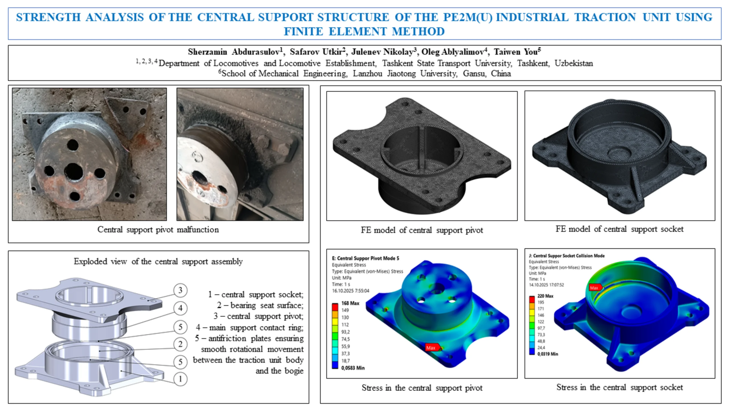
- Central support pivot malfunction
- Exploded view of the central support assembly
- FE model of central support pivot
- FE model of central support socket
- Stress in the central support pivot / Stress in the central support socket
1. Introduction
Rail transport ensures the efficient transportation of large volumes of cargo on industrial, national, and intercontinental routes. It possesses several unique advantages over other modes of transport, including lower energy consumption, reduced aerodynamic resistance, and decreased rolling resistance due to the specific distribution of force at the wheel-rail interface. These benefits are supported by the necessity for appropriate infrastructure, including high-quality railway tracks, reliable energy supply, and comprehensive safety systems [1-4].
Today, more than 70 traction units of PE2M(U) and MPE2U types are actively used for transporting various mining industry cargo at mining enterprises in the Republic of Uzbekistan, such as JSC “Uzbekcoal” and JSC “Almalyk Mining and Metallurgical Combine,” which have their own railways [5]-[7]. The majority of vehicles in the locomotive fleets of these enterprises consist of PE2M(U) type traction units, which have been in use for 30-55 years. The manufacturer-specified warranty service life of these traction units is at least 24 years [7].
Traction units of the PE2M(U) and MPE2U types are manufactured based on the PE2 traction unit and represent its gradually modernized and improved versions. PE2 type traction units are designed for operation on DC (3000V or 1500V) electrified railways of open-pit mines with a directional slope of up to 60 ‰ [10-12]. Production of this type of traction unit began in 1967. Specifically, 20 PE2 units were produced in 1967-70, 705 PE2M units in 1970-85, and 174 PE2U traction units in 1985-2019 by the Dnipro Electric Locomotive Plant [13]. The MPE2U traction unit, due to increased production volumes and the development of new deposits, has been manufactured by the Tbilisi Electric Locomotive Plant in 2020-21 by order of JSC “Almalyk Mining and Metallurgical Combine,” with 2 units produced to date [13]. This type of traction unit is considered an industrial electric locomotive, consisting of a control electric locomotive and two motor dumpcars [10]-[12].
In recent years, the traction unit fleet of major industrial enterprises has not undergone sufficient renewal. The last additions to their fleets were the PE2U and modernised MPE2U traction units manufactured between 2010-2016 and 2020-2021. This limited modernisation does not meet the growing demand for traction units arising from Uzbekistan’s rapid economic development and expansion of the mining industry. Furthermore, several planned investment projects for fleet renewal have been postponed due to recent geopolitical circumstances, compelling enterprises to seek alternative strategies for modernisation. One effective approach involves assessing the residual resource of existing units and extending their service life, which enables both efficient resource utilisation and cost savings.
The safety of traction rolling stock is fundamentally determined by the strength of its load-bearing structures. These include the body frame, bogie frame, and centre pivot assemblies that connect them and transmit traction and braking forces [14], [15]. Industrial traction units such as the PE2M(U) series have operated far beyond their initial design life while continuing to perform under demanding conditions. However, previous studies have mainly addressed overall frame stiffness and bogie dynamics [6-9], with limited focus on the central support assembly – a key component governing the interaction between the body frame and bogie. Evaluating the static and impact strength of this assembly provides a more accurate understanding of the structural reliability of ageing traction units. This research aims to address that gap through a finite element analysis validated by international standards and previous analytical investigations.
According to Regulation P.15.01-2009 “Locomotives. Procedure for Extending the Designated Service Life”, the feasibility of extending a locomotive’s operational life is determined based on the resource capacity of its primary structural components – the bogie frame, body frame, and other load-bearing elements – established through comprehensive scientific assessment.
2. Bogie connections to the body
The control electric locomotive of the traction unit and the bodies of two motorized dump trucks are each mounted on two two-axle bogies through one central support and two sliding side supports. These supports serve to transmit vertical, horizontal, longitudinal, and transverse forces between the body and the bogie. Vertical loads are transferred from the body to the bogie through a rigid central support and two sliding side supports.
Fig. 1Exploded view of the central support assembly: 1 – central support socket; 2 – bearing seat surface; 3 – central support pivot; 4 – main support contact ring; 5 – antifriction plates ensuring smooth rotational movement between the traction unit body and the bogie
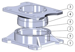
Additionally, the central support functions to transmit horizontal longitudinal and transverse forces between the bogie and the body, as well as acting as a pivot pin, ensuring the rotation of the bogie in the horizontal plane. To reduce wear, flat plates 15 and 16 and bushings 13 and 14 are installed on the pivot and socket (Fig. 1) [5], [11]. The pivot of the central support and the socket are fastened to plates with special holes on the transverse beams of the body frame and the bogie frame using 8 M30 bolts and nuts.
During the examination of the technical condition of PE2U-026, PE2M-029, and PE2U-008 traction units belonging to JSC “Uzbekcoal,” which underwent major repairs with extended service life, fractures and large cracks were observed in their central support pivot (Fig. 2). To determine the properties of this element’s material, test samples were taken from the pivot of the central support of the PE2U-026 traction unit, which was manufactured 38 years ago (as of 2024). Laboratory tests were then conducted on these samples.
The central support socket and pivot are cast from 20L grade steel [5], [11], and the material properties obtained from standard and long-term operational testing are presented in Table 1. According to the test results, we can observe that the mechanical properties of the central support pivot material have changed, specifically becoming more brittle. This indicates the necessity for in-depth diagnostics of this component, which has been in service for over 30-35 years, during major overhaul, and replacement if cracks are detected.
According to laboratory test results, the mechanical properties of the central support elements’ material underwent significant changes compared to the standard over a 38-year service period. Specifically, the yield strength and ultimate tensile strength increased, while the relative elongation decreased. This indicates that the material has strengthened and become brittle after long-term use. Furthermore, these results suggest that these components operate under high-stress conditions.
Fig. 2Central support pivot malfunction
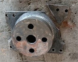
a) Fracture of central support pivot
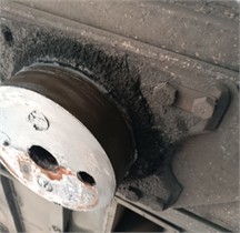
b) Central support pivot crack
Table 1Mechanical properties of the central support pivot material
Condition | Yield strength, [MPa] | Tensile strength, [MPa] | Relative elongation [%] | Hardness [HB] |
By normative | 216 | 412 | 22 | 116-144 |
Test result | 337 | 573 | 16 | 149-156 |
3. Assessment of the strength of central support elements
3.1. Strength calculation mode
The body of the traction unit’s control locomotive and motor dumpcar rests on two bogies. In this configuration, the weight of the body is evenly distributed among the two side supports and the central support. We calculate the acting forces using the characteristics of the traction unit presented in Table 2. According to GOST 34939-2023 [16], the connection nodes between the main frame transmitting the traction force and the bogie frame are calculated under the influence of inertial forces arising from the longitudinal acceleration of the bogie (±3 g). In this case, the stresses in the elements of the connection nodes should not exceed the value of [17], [18]. In this calculation mode, the central support elements are subjected to static gravity force, additional vertical force, and the inertial forces of the bogie.
Taking into account that the vertical static weight force acting on the central support elements is distributed across two bogies and two side supports on each bogie, we calculate it by reducing it by 4 times using Eq. (1):
Table 2Characteristics of the PE2U traction unit
Parameters | Indicators |
Mass of the control locomotive, | 120 t |
Bogie mass, | 24.5 t |
Max. collision force, | 2500 kN |
Control electric locomotive base, | 9.8 m |
Distance from the locomotive body’s center of gravity to the bogie support surface, | ≈ 2 m |
The traction units are designed to withstand impact forces of = 2500 kN [5]. Taking into account that the additional vertical force applied to the central support elements, resulting from the longitudinal inertial force of the body during collision, is equally distributed between the side and central supports, we calculate it using Eq. (2):
We calculate using Eq. (3) for the mass of the bogie, which has increased the body’s inertia force by 40 % during collision, taking into account the moments of inertia of the bogie’s rotating parts:
We calculate the inertial force of the bogie using Eq. (4):
The forces acting in all calculation modes, computed using the equations above, are presented in Table 3.
Table 3Calculated applied forces [kN]
Static gravity | Additional vertical force | Inertial force of the bogie |
174.13 | 18.23 | 721.04 |
3.2. Finite element analysis of central support elements
Today, the finite element method (FEM) is considered one of the standard methods for calculating the strength of locomotive load-bearing structures. In particular, a number of international standards [19], [20] strictly require the use of FEM when calculating the strength of locomotive load-bearing structures. Additionally, many researchers [21-29] around the world are extensively applying FEM in their studies.
To calculate the stresses occurring in the central support elements, their 3D models were created using SolidWorks software. Finite element analysis was performed using the Ansys program, applying the forces listed in Table 3. Finite element analyses were conducted separately for the central support socket and pivot. In this process, vertical forces were applied in a generalized manner to their flat supporting surfaces, while longitudinal horizontal forces were applied to the cylindrical supporting surfaces.
The finite element model of the central support socket consists of 452004 nodes and 280393 elements with a size of 5 mm. The finite element model of the central support pivot comprises 468381 nodes and 289162 elements with a size of 5 mm (Fig. 3(a, b)). To enhance the accuracy of the results, calculations were performed using the FEM calculation methodology for various element sizes, and the results were compared to determine the element size at which stress variation reached a minimum level. Calculations were carried out using this element size.
According to the calculations using the finite element method, it was determined that stress levels of 168 MPa in the pivot of the central support and 220 MPa in the central support socket were generated (Fig. 3(c, d)). These calculated stress values constitute 78 % of the permissible value () for the pivot of the central support and 102 % for the central support socket.
In previous strength analyses of traction units, the structural integrity of the central support components had not been examined separately in accordance with the requirements of national strength standards.
The present study complements those earlier investigations by providing a more detailed and standard-based assessment of the central support elements, offering clear and quantitatively justified conclusions regarding their structural strength and operational reliability.
Fig. 3Example of figure consisting of multiple charts

a) FE model of central support pivot

b) FE model of central support socket
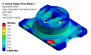
c) Stress in the central support pivot
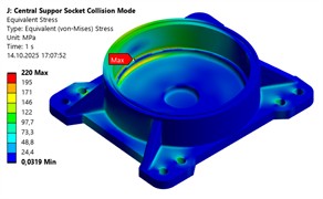
d) Stress in the central support socket
4. Conclusions
According to the calculation results, it was determined that the stress value occurring at the pivot of the central support constitutes 78 % of the permissible value, while for the central support socket, it amounts to 102 %. Based on this, the following conclusions can be drawn:
1) Fractures in the central support pivot were caused by technological or manufacturing defects.
2) The stress value in the central support socket exceeds the permissible norm by 12 %. This justifies the need for the manufacturing plant to either improve the design of this component or produce it using steel grades with higher strength to ensure compliance with the requirements of the newly implemented standard.
3) When repairing traction units that have been in use for extended periods, enterprises operating these units must pay special attention to thoroughly inspect areas with high stress concentration in the components.
Although the static stress analysis provides a valid estimation of structural response, the study acknowledges that additional uncertainty and sensitivity assessments would further refine the quantitative interpretation. Future research will therefore focus on parametric variations in socket geometry, load application, and material properties to better understand their influence on stress distribution and service life prediction.
References
-
A. Lovska, J. Dižo, V. Ravlyuk, D. Skurikhin, and A. Rybin, “Reduction of stresses in a passenger car frame under operating modes by means of an intermediate adapter,” Acta Technica Jaurinensis, Vol. 18, No. 3, pp. 114–122, May 2025, https://doi.org/10.14513/actatechjaur.00779
-
D. Alic, A. Miltenovic, M. Banic, and R. V. Zafra, “Numerical investigation of large vehicle aerodynamics under the influence of crosswind,” Spectrum of Mechanical Engineering and Operational Research, Vol. 2, No. 1, pp. 13–23, Jan. 2025, https://doi.org/10.31181/smeor21202526
-
M. Gorbunov et al., “Estimation of sand electrification influence on locomotive wheel/ rail adhesion processes,” Eksploatacja i Niezawodność – Maintenance and Reliability, Vol. 21, No. 3, pp. 460–467, Sep. 2019, https://doi.org/10.17531/ein.2019.3.12
-
S. Fischer, “Investigation of the settlement behavior of ballasted railway tracks due to dynamic loading,” Spectrum of Mechanical Engineering and Operational Research, Vol. 2, No. 1, pp. 24–46, Jan. 2025, https://doi.org/10.31181/smeor21202528
-
S. Abdurasulov, N. Zayniddinov, A. Yusufov, S. Jamilov, and F. Khikmatov, “Characteristics of industrial traction units and their load-bearing structures,” Journal of Transport, Vol. 1, No. 4, pp. 45–53, Dec. 2024, https://doi.org/10.56143/2181-2438-2024-4-45-53
-
S. Abdurasulov, N. Zayniddinov, A. Yusufov, and S. Jamilov, “Analysis of stress-strain state of bogie frame of PE2U and PE2M industrial traction unit,” in E3S Web of Conferences, Vol. 401, p. 04022, Jul. 2023, https://doi.org/10.1051/e3sconf/202340104022
-
S. Abdurasulov, N. Zayniddinov, O. Khamidov, A. Yusufov, and S. Jamilov, “Stress-strain state analysis of cross beam of main frame of industrial electric locomotives PE2M and PE2U,” in The 3rd International Symposium on Civil, Environmental, and Infrastructure Engineering (ISCEIE) 2024, Vol. 3317, No. 1, p. 060011, Jan. 2025, https://doi.org/10.1063/5.0266927
-
D. Bannikov, A. Radkevich, and A. Muntian, “Modernization of the buffer beam of PE2U traction unit electric locomotive,” in IOP Conference Series: Materials Science and Engineering, Vol. 985, No. 1, p. 012035, Nov. 2020, https://doi.org/10.1088/1757-899x/985/1/012035
-
O. M. Bondaryev, V. L. Gorobets’, Y. M. Dzichkovs’Kyy, O. Y. Kryvchykov, D. O. Yagoda, and V. S. Bondaryeva, “Estimation of strength indices of parts of supporting structures of traction assemblies OPE1A and prolongation of their service life,” Science and Transport Progress, No. 40, pp. 17–27, Apr. 2012, https://doi.org/10.15802/stp2012/6919
-
V. Rakov, Locomotives and Multiple Unit Rolling Stock of the Soviet Union Railways, 1976-1985. Moscow: Transport, 1990.
-
V. Bratash, Electric Locomotives and Traction Units for Industrial Transport. Moscow: Transport, 1977.
-
L. Balon, V. Bratash, and M. Bichuch, Electric Rolling Stock of Industrial Transport. Moscow: Transport, 1987.
-
S. Abdurasulov and N. Zayniddinov, “Increasing the efficiency of operation of industrial traction units in the Republic of Uzbekistan,” in Railway Rolling Stock: Problems, Solutions, Prospects, pp. 3–9, 2024.
-
E. S. Oganyan, G. M. Volokhov, A. S. Gasyuk, and D. M. Fazliakhmetov, “Calculated experimental evaluation of the operating life of basic locomotive parts for ensuring their safe operation,” Journal of Machinery Manufacture and Reliability, Vol. 47, No. 2, pp. 155–159, Apr. 2018, https://doi.org/10.3103/s1052618818020097
-
E. S. Oganyan, G. M. Volohov, and A. S. Gasyuk, “Justification of safe operation of rolling stock by the lifetime of its bearing structures,” in IOP Conference Series: Materials Science and Engineering, Vol. 1079, No. 5, p. 052089, Mar. 2021, https://doi.org/10.1088/1757-899x/1079/5/052089
-
“Locomotives. Requirements for bearing structure strength and dynamic properties,” GOST 34939-2023, 2023.
-
S. Abdurasulov, N. Zayniddinov, and A. Yusufov, “Requirements for the strength of load-bearing structures of locomotives,” Acta of Turin Polytechnic University in Tashkent, Vol. 13, No. 4, pp. 44–48, 2023.
-
S. Abdurasulov, N. Zayniddinov, and K. Kosimov, “Strength requirements for locomotive load-bearing structures: a literature review,” International Scientific Journal Engineer, Vol. 3, No. 1, pp. 14–18, Mar. 2025, https://doi.org/10.56143/3030-3893-2025-1-14-18
-
“Railway applications – Structural requirements of railway vehicle bodies – Part 1: Locomotives and passenger rolling stock (and alternative method for freight wagons),” EN 12663-1:2010, 2023.
-
“Railway applications – Wheelsets and bogies – Method of specifying the structural requirements of bogie frames,” BSI British Standards, London, EN 13749:2021, Apr. 2024.
-
M. Kassner, “Fatigue strength analysis of a welded railway vehicle structure by different methods,” International Journal of Fatigue, Vol. 34, No. 1, pp. 103–111, Jan. 2012, https://doi.org/10.1016/j.ijfatigue.2011.01.020
-
D. Chen, “Strength evaluation of a bogie frame by different methods,” Mechanical Engineering Science, Vol. 1, No. 1, Jul. 2019, https://doi.org/10.33142/me.v1i1.662
-
C.-K. Lee, C.-K. Liu, and Y.-C. Cheng, “Multi-objective optimal design for the railway bogie frame system under stress and fatigue analysis,” in Journal of Physics: Conference Series, Vol. 2793, No. 1, p. 012010, Jul. 2024, https://doi.org/10.1088/1742-6596/2793/1/012010
-
A. Yusufov, O. Khamidov, N. Zayniddinov, and S. Abdurasulov, “Prediction of the stress – strain state of the bogie frames of shunting locomotives using the finite element method,” in E3S Web of Conferences, Vol. 401, p. 03041, Jul. 2023, https://doi.org/10.1051/e3sconf/202340103041
-
O. Khamidov, A. Yusufov, S. Jamilov, and S. Kudratov, “Remaining life of main frame and extension of service life of shunting Locomotives on railways of Republic of Uzbekistan,” in E3S Web of Conferences, Vol. 365, p. 05008, Jan. 2023, https://doi.org/10.1051/e3sconf/202336505008
-
A. Grishchenko, A. M. Yusufov, and D. N. Kurilkin, “Forecasting the residual service life of the main frame and extending the service life of shunting locomotives JSC “UTY”,” in E3S Web of Conferences, Vol. 460, p. 06032, Dec. 2023, https://doi.org/10.1051/e3sconf/202346006032
-
J.-W. Seo, H.-M. Hur, S.-J. Kwon, and K.-H. Moon, “Effect of multiple weld repairs on fatigue strength of bogie frame of railroad vehicle,” Advances in Mechanical Engineering, Vol. 15, No. 11, Nov. 2023, https://doi.org/10.1177/16878132231213596
-
Z. Mukhamedova et al., “Calculating the fatigue strength of load-bearing structures of special self-propelled rolling stock,” Scientific Reports, Vol. 14, No. 1, p. 19205, Aug. 2024, https://doi.org/10.1038/s41598-024-70169-0
-
C. Miao, H. Wang, and Y. Song, “The correlation between static strength and fatigue strength test and simulation,” in Journal of Physics: Conference Series, Vol. 2660, No. 1, p. 012042, Dec. 2023, https://doi.org/10.1088/1742-6596/2660/1/012042
About this article

The authors have not disclosed any funding.
The datasets generated during and/or analyzed during the current study are available from the corresponding author on reasonable request.
The authors declare that they have no conflict of interest.
