Abstract
Segmental assembled piers have gained increasing attention in bridge engineering due to their superior construction efficiency, shortened construction periods, and reduced on-site wet work. However, their application in high-seismic-intensity regions remains limited because the mechanical performance of segment joints is generally weaker than that of conventional monolithic piers. This concern is particularly critical for high-speed railway bridges, which demand exceptional structural stability and seismic safety. To address this issue, energy dissipation bars were introduced into a segmental assembled round-end hollow pier to enhance its seismic resilience. A nonlinear finite element model was developed and validated against experimental results to ensure the reliability of the numerical approach. Based on the validated model, the effects of key design parameters of the energy dissipation bars were systematically investigated, and dynamic time-history analyses were conducted to evaluate seismic responses under different earthquake motions. The results demonstrate that increasing the sectional contribution ratio of the energy dissipation bars markedly improves the lateral resistance, energy dissipation capacity, and loading-unloading stiffness of the pier. However, this enhancement also results in larger residual drift angles, indicating a trade-off between seismic robustness and post-earthquake recoverability. Compared with the diameter and quantity of the bars, their arrangement shows a relatively limited influence on seismic performance. Moreover, the vibration mitigation effectiveness becomes increasingly significant with rising peak ground acceleration (PGA), achieving reduction rates exceeding 60 %. Nevertheless, severe plastic deformation and damage to the energy dissipation bars were observed under strong earthquakes, which indirectly amplify residual displacements. Additionally, the pier exhibits substantially stronger seismic responses under near-field ground motions than under far-field motions. In particular, near-field pulse-like earthquakes significantly amplify the pier-top displacement, suggesting that special design considerations are necessary when deploying such piers in near-fault regions. This study provides important insights into the seismic performance and design optimization of segmental assembled hollow piers for high-speed railways, offering valuable theoretical support and practical guidance for their application in seismic regions.

Highlights
- Energy dissipation bars significantly enhance the seismic performance of segmentally assembled round-end hollow piers.
- Larger bar diameter and quantity markedly improve strength, stiffness, and energy dissipation capacity.
- Residual displacement depends strongly on bar design; excessive displacement angles may cause irreparable damage.
- Near-field pulse-like earthquakes induce substantially greater responses than far-field motions.
1. Introduction
A precast segmental assembled pier is constructed by dividing the pier body into several segments that are prefabricated in a factory and then interconnected using pre-stressed tendons. Each pier segment contains longitudinal reinforcements to support forces, but these reinforcements are not continuous at the joints between segments, making these joints the weaker points for bearing forces in the pier. Studies [1-3] have revealed that, in comparison to cast-in-place reinforced concrete piers, while segmental assembled piers exhibit minimal residual displacement and good self-centering ability, they display a pronounced pinch in the hysteretic curve, indicating a weak energy dissipation capacity. Additionally, the horizontal bearing capacity of the pier top is lower than that of similar cast-in-place piers, restricting the widespread adoption of this pier type in high-intensity seismic zones. To enhance the seismic performance and safety of segmental assembled piers in high-intensity regions, researchers globally have delved into vibration absorption measures for these piers. The seismic design of segmental assembled piers has primarily focused on three key aspects:
(1) The structural form of a segmental assembled pier includes elements such as semi-precast and semi-cast-in-place techniques [1] [4-7], mortise-tenon joints [8], and connections between pier segments using flanges [9].
(2) Incorporating novel materials such as Ultra High-Performance Concrete (UHPC) [10-13], Fiber Reinforced Polymer (FRP) [14-18], Fiber-Reinforced Concrete (FRC) [19-20], Engineered Cementitious Composite (ECC) [17], among others.
(3) Establish energy dissipation and vibration absorption elements, including energy dissipation bar [8], [20], [21-25], viscoelastic damper [8], [26-28], external energy dissipation steel bar [29-32], external energy dissipation steel plate [33], energy dissipation bearing at pier bottom [20], stop bolt [34], shape memory alloys (SMA) bar [35], [36], and aluminum alloy steel bar [37].
Segmental assembled piers with vibration absorption measures have demonstrated enhanced seismic performance due to the vibration absorption effect. Each seismic performance index has shown varying degrees of improvement.
Considering the segmental assembled round-end hollow pier discussed in this study is primarily utilized in the construction of high-speed railway bridges, which necessitate high stability and seismic safety, the implementation of vibration absorption techniques is crucial to enhance the seismic resilience of high-speed railway bridges utilizing this type of pier. In this research, a straightforward energy dissipation bar with a simple design and efficient energy dissipation capabilities was chosen to mitigate vibrations in the segmental assembled round-end hollow pier. The study focuses on evaluating how the primary de-sign parameters of the energy dissipation bar influence the seismic performance of the pier.
Nevertheless, it is important to highlight that the seismic performance of the seg-mental assembled round-end hollow pier can be improved through the implementation of vibration absorption techniques. This enhancement results in a more complete hysteretic curve, consequently leading to a higher residual displacement of the pier following an earthquake. During the Kobe earthquake in 1995, approximately 100 piers within the Hanshin Expressway viaduct sustained minor to moderate damage [38]. Regrettably, these piers could not be restored due to excessive residual displacement. Research [39] following the Kobe earthquake revealed that when the residual displacement angle surpasses 1 %, the repair duration and costs significantly escalate. Similarly, if the residual displacement angle exceeds 1.75 %, repairing the pier post-earthquake becomes unfeasible, necessitating demolition and reconstruction. As a result, this study defines the 1 % and 1.75 % residual displacement angles as thresholds to differentiate between easily reparable, repairable, and challenging repair scenarios.
In conclusion, enhancing the seismic performance of segmental assembled round-end hollow piers is a pressing issue. It is essential to efficiently manage the residual displacement of the piers post-earthquake and ensure their self-centering capability. By focusing on controlling residual displacement, optimizing the seismic performance of segmental assembled round-end hollow piers involves adjusting the design parameters of the energy dissipation bar. This optimization aims to enhance the seismic safety of these piers when utilized in areas of high intensity seismic activity.
2. Numerical modeling and validation of a segmental assembled round-end hollow pier
In this study, the pseudo-static test outcomes of a segmental assembled round-end hollow pier conducted by our research team are utilized to refine the numerical model of the pier [40].
2.1. Experimental results
Based on a standard precast assembled pier from the Yinchuan-Lanzhou High-speed Railway as a structural reference, a 1:5 large-scale test model was devised and finalized. The test specimen consisted of a segmentally assembled prestressed concrete (PSC) round-end hollow pier, as shown in Fig. 1. The test model stood at an effective height of 2800 mm, with a wall thickness of 140 mm, and an outer wall dimension of 1240 mm × 600 mm. The concrete was de-signed with a strength grade of C40. Longitudinal reinforcement consisted of HRB400 bars with a diameter of 12 mm, with 18 bars arranged in both the inner and outer rings. HPB400 bars with diameters of 8 mm and 6 mm were utilized as stirrups and lacing bars, correspondingly. The key design specifications of the model are detailed in Table 1.
Fig. 1Segmental assembled round-end hollow pier (unit: mm)
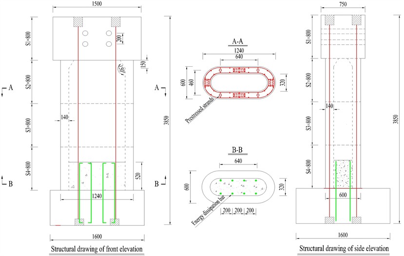
Fig. 2Test model and results. Note: Photograph of the quasi-static test of a precast segmental column, taken by Hao Li in August 2020 at the Structural Testing Laboratory of Yantai University
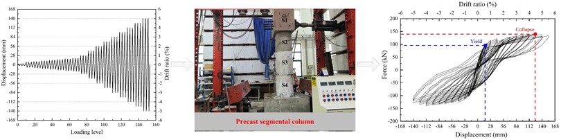
The test specimen underwent loading under displacement control. To identify the initial yield point of the pier, a minor change in displacement was applied during the early loading stage. Once the strain of the longitudinal reinforcement at the base of the pier reached 2000, the current loading displacement marked the initial yield point of the pier. Concurrently, the horizontal resistance at the pier's peak denoted the initial yield force. Subsequent to the pier yielding, the displacement changes during loading intensified. At a specific displacement amplitude, when the pier’s horizontal resistance reduced to below 80 % of its maximum, the corresponding displacement was deemed the ultimate dis-placement of the pier. Simultaneously, the horizontal resistance at the top of the pier at this juncture represented the ultimate bearing force. The findings of the pseudo-static test are depicted in Fig. 2.
Table 1Design parameters of test pier model
Test specimen | Reinforcement ratio | Stirrup ratio | Permanent load (kN) | Axial compression ratio | Prestress (N) | Shear span ratio | Ratio of energy dissipation bar (%) |
PSC | 1.07 % | 0.9 % | 524 | 7.5 % | 354000 | 4.7 | 0.59 |
Note: the reinforcement ratio and stirrup ratio calculations are based on the hollow net section, while the reinforcement ratio calculation for the energy dissipation bar is based on the solid gross section | |||||||
2.2. Finite element model development
Based on the experimental model, a fiber-based finite element model of the PSC specimen was established in OpenSees, as shown in Fig. 3. Both the cover and core concretes were modeled with the Concrete01 material, while the reinforcing bars and prestressing tendons were represented using the Steel02 material. Prestressing tendons were simulated with truss elements, with their top nodes rigidly connected to the pier model and the bottom nodes fixed. Bonded energy dissipation bars were discretized at the corresponding locations within the fiber section, whereas unbonded energy dissipation bars were modeled using truss elements with fixed bottom constraints.
Fig. 3Finite element modeling method for the segmental assembled round-end hollow pier
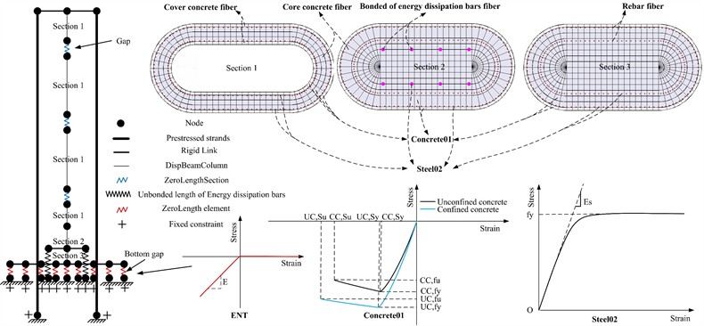
To accurately capture the contact behavior between segments, the bottom joint was simulated using compression-only springs with the ENT (Elastic-No Tension) material. The remaining hollow joints were modeled with zero-length section elements using the same ENT material, with fiber layouts consistent with those of the adjacent sections.
Nonlinear analysis was performed using the Krylov-Newton algorithm, and the displacement increment norm (NormDispIncr) was adopted as the convergence criterion to ensure computational accuracy and stability.
For fiber section discretization, 544 fibers were assigned to the solid segment and 356 fibers to the hollow segment. Previous studies indicate that numerical accuracy is sufficient when the number of fibers exceeds 200; therefore, the adopted discretization meets the requirements for reliable numerical analysis.
2.3. Model validation
The finite element software OpenSees was utilized to analyze the hysteresis behavior of the pier model, and the numerical simulation results were subsequently compared with the experimental findings.
Fig. 4Hysteresis curve
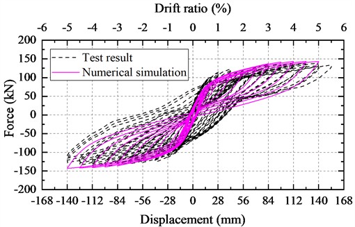
Fig. 5Skeleton curve
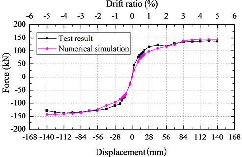
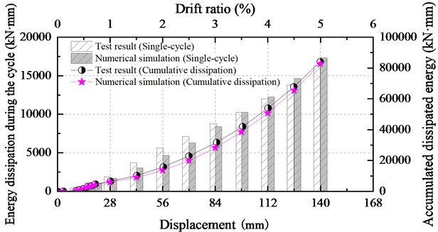
The comparison between the numerical simulation and experimental results is presented in Figs. 4-6. The maximum horizontal resistance at the pier top obtained from the numerical simulation is 143.4 kN, while the experimental value is 137.8 kN, corresponding to an error of 4.1 %. The cumulative energy dissipation is 82725.9 kN⋅mm in the simulation and 84086.7 kN⋅mm in the experiment, resulting in an error of 1.6 %.
Overall, the numerical and experimental results show good agreement in terms of the hysteretic response, skeleton curve, and energy dissipation capacity. Small differences exist due to modeling assumptions, material idealization, and experimental uncertainties; however, these discrepancies remain within an acceptable range and satisfy the requirements for engineering reference. The results indicate that the nonlinear finite element model can reliably capture the mechanical behavior of the segmentally assembled round-end hollow pier.
Fig. 6Energy dissipation
3. Study on the impact of energy dissipation bars on the hysteretic response of segmental assembled round-end hollow piers
3.1. Effect of energy dissipation bar diameter
The diameter of the energy dissipation bar is a crucial design parameter that impacts the seismic performance of segmental assembled piers. It directly influences the energy dissipation capacity of each bar. This section explores the effect of the energy dissipation bar diameter on the seismic performance indicators of segmental assembled piers. The diameter range studied was set at 10-35 mm with a 5 mm increment. Table 2 illustrates the changes in the diameter of the energy dissipation bar, while the quantity and layout of the energy dissipation bar are depicted in Fig. 7.
Fig. 7Energy dissipation bar arrangement (unit: mm)
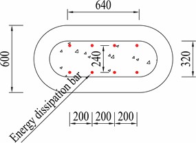
Table 2Change of diameter of energy dissipation bar
Type of pier | Diameter of energy dissipation bar (mm) | Quantity of energy dissipation bar | Contribution rate of energy dissipation in bars section % |
PSCE1 | 10 | 8 | 0.09 |
PSCE2 | 15 | 8 | 0.21 |
PSCE3 | 20 | 8 | 0.38 |
PSCE4 | 25 | 8 | 0.59 |
PSCE5 | 30 | 8 | 0.85 |
PSCE6 | 35 | 8 | 1.15 |
The numerical models for the piers were developed using the corrected numerical modeling method mentioned earlier. Subsequently, a hysteretic analysis was conducted, with the displacement loading system matching that of the test. The findings of the calculations are illustrated in Fig. 7.
Based on the examination of Fig. 8(a) and (b), as the diameter of the energy dissipation bar increases, the bearing capacity of each energy dissipation bar and the horizontal resistance of the segmental assembled pier show a continuous increase. The maximum horizontal resistance of PSCE1 is 96.2 kN, while for PSCE6, it reaches 196.8 kN, resulting in a horizontal resistance that is 2.05 times higher than the original value.
Fig. 8Impact of energy dissipation bar diameter on hysteretic behavior of bridge piers
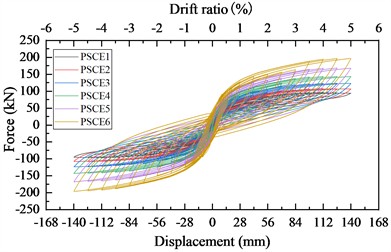
a) Hysteresis curve
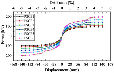
b) Skeleton curve
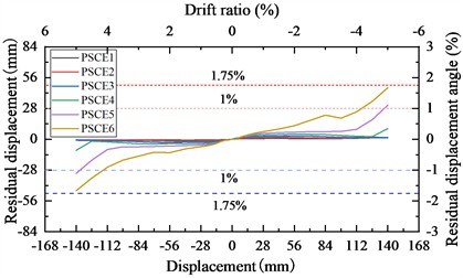
c) Residual displacement
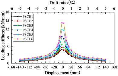
d) Loading stiffness
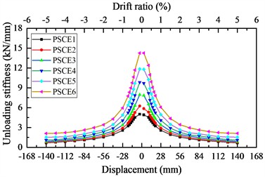
e) Unloading stiffness
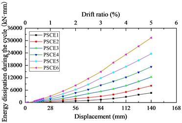
f) Hysteretic energy dissipation
The analysis of Fig. 8(c) reveals that as the segmental assembled pier oscillates, the energy dissipation bar undergoes collaborative deformation. As the diameter of the energy dissipation bar increases, the plastic deformation of each energy dissipation bar also increases, leading to a rise in the residual deformation of the segmental assembled pier following the reciprocating motion. This effect is more pronounced with larger loading displacements, as the greater the displacement amplitude, the deeper the energy dissipation bar enters the plastic state, resulting in a larger residual deformation post reciprocating motion. Consequently, during the later stages of the loading process, the variation in residual deformation becomes more apparent among segmental assembled piers with energy dissipation bars of different diameters. The maximum residual displacement is 1.38 mm for PSCE1, 46.83 mm for PSCE6, with the latter experiencing a residual displacement 33.93 times that of the original displacement. Notably, for PSCE5, a loading displacement amplitude of 140 mm causes the residual displacement angle to exceed 1 %; while for PSCE6, at 126 mm loading displacement amplitude, the residual displacement angle also surpasses 1 %, further escalating to over 1.75 % at a loading displacement amplitude of 140 mm.
Based on the analysis of Fig. 8(d) and (e), it is observed that as the diameter of the energy dissipation bar increases, the force required for unit deformation of each energy dissipation bar also increases. This, in turn, leads to a rise in the loading stiffness and un-loading stiffness of the segmental assembled pier. Specifically, the maximum loading stiffness of PSCE1 is 4.8 kN/mm, while that of PSCE6 is 14.26 kN/mm, representing 2.97 times increase from the original value. Similarly, the maximum unloading stiffness of PSCE1 is 5.02 kN/mm, and for PSCE6, it is 14.27 kN/mm, indicating 2.84 times increase from the original stiffness.
The analysis of Fig. 8(f) indicates that as the diameter of the energy dissipation bar increases, the energy dissipation capacity of each bar also rises, consequently enhancing the overall energy dissipation capability of segmental assembled piers. Moreover, as the loading displacement amplitude increases, the penetration of each energy dissipation bar into the plastic state deepens, leading to a more effective energy dissipation performance. The maximum energy dissipation for a single cycle of PSCE1 is 4689.36 kN⋅mm, while for PSCE6, it reaches 31351.15 kN⋅mm. This represents a significant increase, with the maximum energy dissipation for a single cycle being 6.69 times greater than the original value.
3.2. Effect of energy dissipation bar quantity
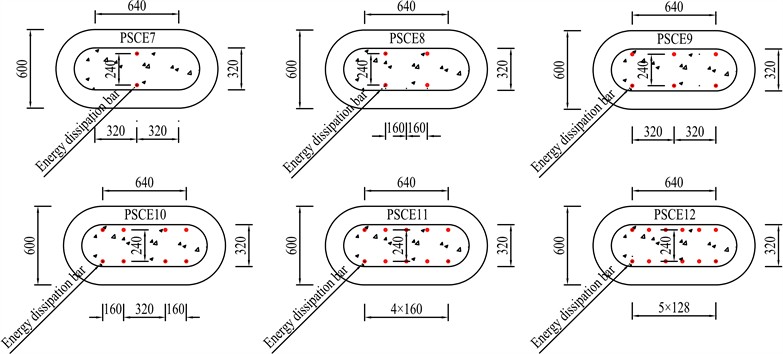
When determining the diameter of the energy dissipation bar, the energy dissipation capacity level of each bar is established. The total energy dissipation capacity level of the bars is influenced by the quantity of energy dissipation bars utilized. As a result, the quantity of energy dissipation bars plays a crucial role in determining the seismic performance of the segmental assembled pier. Designers must carefully choose the quantity of energy dissipation bars to ensure that the segmental assembled pier can meet the desired seismic performance standards. This study aims to investigate how the quantity of energy dissipation bars impacts the seismic performance indicators of segmental assembled piers. The range of variation for the quantity of energy dissipation bars was set between 2 and 12, with an increment of 2, as outlined in Table 3. The diameter of the energy dissipation bar was established at 25 mm, with the detailed arrangement shown in Fig. 9.
Fig. 9Arrangement of energy dissipation bars of varying quantities (unit: mm)
The hysteresis analysis of the numerical models using OpenSees was performed, and the findings are illustrated in Fig. 10.
Based on the examination of Fig. 10(a) and (b), incorporating additional energy dissipation bars resulted in an increase in the overall bearing capacity of these bars. Consequently, this enhancement indirectly elevated the horizontal bearing capacity of the segmental assembled piers. The PSCE7 exhibited a maximum horizontal resistance of 101.27 kN, while the PSCE12 displayed 171.74 kN. Notably, the horizontal reaction was amplified to 1.70 times its original value.
Table 3Change of quantity of energy dissipation bar
Type of pier | Diameter of energy dissipation bar (mm) | Quantity of energy dissipation bar | Contribution rate of energy dissipation in bars section % |
PSCE7 | 25 | 2 | 0.15 |
PSCE8 | 25 | 4 | 0.29 |
PSCE9 | 25 | 6 | 0.44 |
PSCE10 | 25 | 8 | 0.59 |
PSCE11 | 25 | 10 | 0.74 |
PSCE12 | 25 | 12 | 0.88 |
Fig. 10Influence of the quantity of energy dissipation bar on the hysteretic behavior of the pier
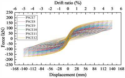
a) Hysteresis curve
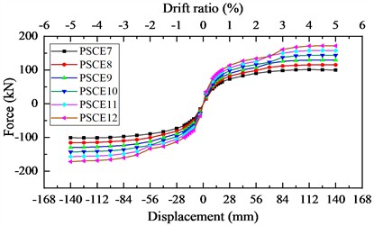
b) Skeleton curve
c) Residual displacement
d) Loading stiffness
e) Unloading stiffness
f) Hysteretic energy dissipation
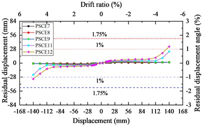
The analysis of Fig. 10(c) reveals that as the number of energy dissipation bars increases, the total residual displacement of the energy dissipation bar post-reciprocation also increases. This subsequently elevates the residual displacement of the segmental assembled pier after an earthquake. Additionally, with a higher loading displacement amplitude, the difference in residual displacement among models with varying numbers of energy dissipation bars becomes more pronounced. This is primarily due to the increased loading displacement amplitude intensifying the plastic state penetration of each energy dissipation bar. Specifically, the maximum residual displacement is 1.55 mm for PSCE7 and significantly higher at 33.21 mm for PSCE12, representing a 21.43-fold increase from the original displacement. Notably, when the loading displacement amplitude reaches 140 mm for PSCE12, the residual displacement angle surpasses 1 %.
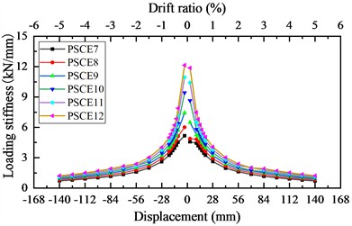
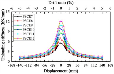
Moreover, the analysis depicted in Fig. 10(d) and (e) illustrates that as the number of energy dissipation bars rises, the total thrust stiffness of these bars increases, consequently enhancing the loading and unloading stiffness of segmental assembled piers. The highest loading stiffness is recorded at 5.17 kN/mm for PSCE7 and notably higher at 12.14 kN/mm for PSCE12, representing a 2.35-fold increase from the original stiffness. Similarly, the maximum unloading stiffness reaches 5.57 kN/mm for PSCE7 and 12.13 kN/mm for PSCE12, indicating a 2.18-fold increase from the initial stiffness value.
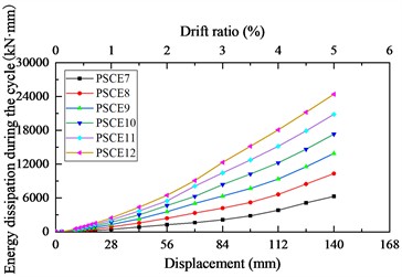
Based on the analysis presented in Fig. 10(f), the overall energy dissipation capacity of the energy dissipation bar increases as the quantity of energy dissipation bars rises. This enhancement indirectly boosts the seismic energy dissipation capability of segmental assembled piers. As the loading displacement amplitude increases, each energy dissipation bar's tendency to reach a plastic state intensifies. Furthermore, the variation in the number of energy dissipation bars significantly influences the total seismic energy dissipation level of segmental assembled piers. Specifically, the maximum dissipation energy for a single cycle of PSCE7 is recorded at 6294.88 kN⋅mm, while for PSCE12, it reaches 24411.12 kN⋅mm. Consequently, the maximum dissipation energy for a single cycle increases to 3.88 times the original value.
3.3. Effect of energy dissipation bar arrangement
Once the diameter of the energy dissipation bar is established, its energy dissipation capacity becomes fixed. Likewise, determining the quantity of energy dissipation bars sets the number available for providing energy dissipation. The arrangement of these bars plays a crucial role in the overall energy dissipation and vibration absorption capabilities, consequently influencing the seismic performance of the segmented assembled pier.
In this section, the energy dissipation bars are evenly distributed along the longitudinal direction of the bridge, with 4 bars on each side. The spacing between the energy dissipation bars on either side ranges from 80 mm to 280 mm, with a variation of 40 mm, as illustrated in Fig. 11. The diameter of the energy dissipation bars is set at 25 mm, with a total of 8 bars determined for installation.
Pier modeling and calculation analysis were conducted using OpenSees, with the outcomes shown in Fig. 12.
Analyzing Fig. 12(a) and (b) reveals that altering the arrangement of the energy dissipation bar impacts both the duration and extent of the energy dissipation bar’s deformation, consequently influencing the lateral resistance of segmental assembled piers. The maximum lateral resistance of PSCE13 is 143.09 kN, while that of PSCE18 is 146.54 kN, resulting in 1.02 times increase from the original value. It is evident that a greater spacing between the energy dissipation bars on each side leads to a higher lateral resistance of the segmental assembled pier. Despite some enhancement, the magnitude of the increase is relatively modest.
Based on the analysis of Fig. 12(c), as the segmental assembled pier undergoes reciprocal movement, the energy dissipation bar deforms accordingly. The reconfiguration of the energy dissipation bar impacts both the timing and extent of its plastic deformation, subsequently influencing the residual displacement of the segmental assembled piers post motion. Notably, the maximum residual displacement is 5.60 mm for PSCE13 and 10.79 mm for PSCE18, showing an increase by a factor of 1.93. However, it is important to highlight that the residual displacement angles of all six numerical models remain within acceptable limits.
Fig. 11Change of arrangement of energy dissipation bar (unit: mm)
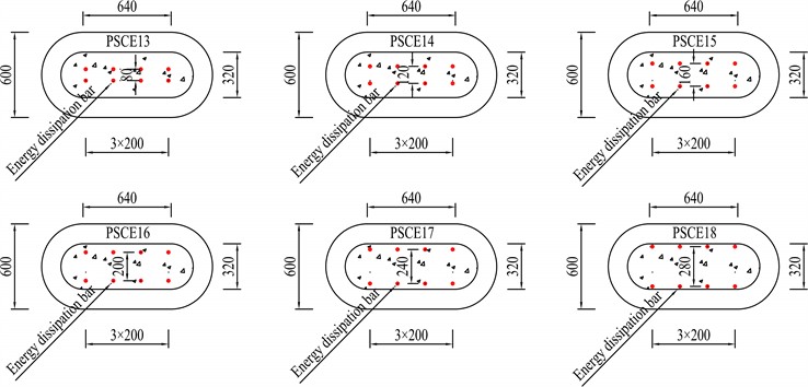
Fig. 12Impact of energy dissipation bar arrangement on hysteretic performance of pier
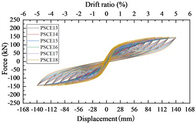
a) Hysteresis curve
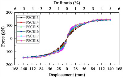
b) Skeleton curve
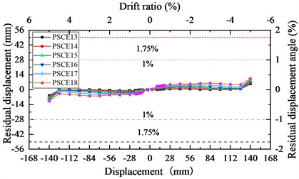
c) Residual displacement
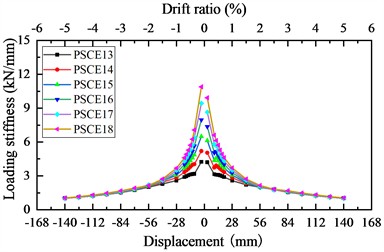
d) Loading stiffness
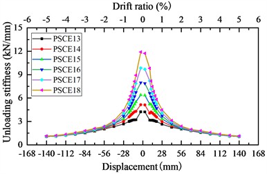
e) Unloading stiffness
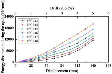
f) Hysteretic energy dissipation
Based on the analysis of Fig. 12(d) and (e), it was found that the maximum loading stiffness of PSCE13 is 4.25 kN/mm, while that of PSCE18 is 10.89 kN/mm. The loading stiffness increased by 2.56 times compared to the original values. In terms of the maximum unloading stiffness, PSCE13 measures at 4.23 kN/mm, and PSCE18 at 11.91 kN/mm. The unloading stiffness increased to 2.82 times of the original values. Nevertheless, as the loading displacement progresses, the loading and unloading stiffness of each numerical model converge due to the consistent lateral stiffness of each energy dissipation bar and the constant total number of energy dissipation bars.
Based on the findings presented in Fig. 12(f), it is evident that the maximum dissipation energy for a single-cycle of PSCE13 is 11600.32 kN·mm, whereas for PSCE18, it amounts to 20138.74 kN·mm. The separation between the energy dissipation bars on either side ranges from 80-280mm, resulting in the maximum dissipation energy for a single-cycle increasing to 1.74 times its original value.
4. Vibration absorption performance of energy dissipation bars under dynamic earthquake loading
The parameterized research results indicate that PSCE4 demonstrates a favorable seismic performance concerning energy dissipation bars. This section examines the vibration absorption impact of energy dissipation bars on piers under various earthquake motions by comparing a segmental assembled round-end hollow pier (PSC) without energy dissipation bars and a segmental assembled round-end hollow pier (PSCE4) with energy dissipation bars.
4.1. Selection of earthquake ground motions
Ten far-field earthquake motions, ten near-field earthquake motions without a pulse, and ten near-field earthquake motions with a pulse were chosen from the PEER database, as outlined in Table 4. Subsequently, the corresponding earthquake motion response spectrum was generated and illustrated in Fig. 13. The far-field earthquake motions originate from fault distances exceeding 30 km, while near-field earthquake motions without a pulse stem from fault distances less than 20 km. On the other hand, near-field earthquake motions with a pulse also come from fault distances less than 20 km, exhibiting a distinct velocity pulse lasting more than 1 second. To analyze the seismic response of the pier to various earthquake intensities, all motions were initially normalized. Following this, the peak acceleration of each earthquake motion was adjusted to 0.2 g, 0.4 g, 0.6 g, 0.8 g, and 1.0 g before being applied to the pier model for computation.
Fig. 13Acceleration response spectrum
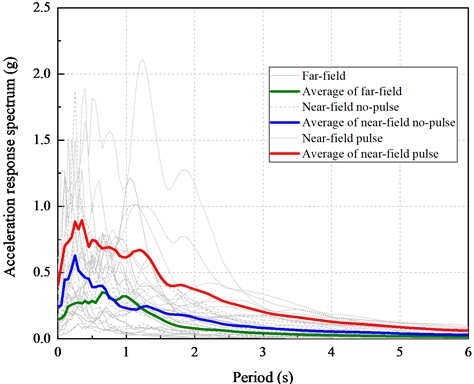
Table 4Thirty earthquake motion records
Type | Number | RSN | Earthquake name | Time of occurrence | Station | Magnitude | Rjb (km) |
Near-field pulse earthquake motion | 1 | 161 | Imperial Valley-06 | 1979 | Brawley Airport | 6.53 | 8.54 |
2 | 180 | Imperial Valley-06 | 1979 | El Centro Array #5 | 6.53 | 1.76 | |
3 | 181 | Imperial Valley-06 | 1979 | El Centro Array #6 | 6.53 | 0 | |
4 | 184 | Imperial Valley-06 | 1979 | El Centro Differential Array | 6.53 | 5.09 | |
5 | 185 | Imperial Valley-06 | 1979 | Holtville Post Office | 6.53 | 5.35 | |
6 | 1084 | Northridge-01 | 1994 | Sylmar - Converter Sta | 6.69 | 0 | |
7 | 1114 | Kobe_ Japan | 1995 | Port Island (0 m) | 6.9 | 3.31 | |
8 | 1120 | Kobe- Japan | 1995 | Takatori | 6.9 | 1.5 | |
9 | 3965 | Tottori_ Japan | 2000 | TTR008 | 6.61 | 6.86 | |
10 | 4107 | Parkfield-02_ CA | 2004 | Parkfield - Fault Zone 1 | 6 | 0.02 | |
Near-field no-pulse earthquake motion | 11 | 6 | Imperial Valley-02 | 1940 | El Centro Array #9 | 6.95 | 6.09 |
12 | 20 | Northern Calif-03 | 1954 | Ferndale City Hall | 6.5 | 26.72 | |
13 | 163 | Imperial Valley-06 | 1979 | Calipatria Fire Station | 6.53 | 23.17 | |
14 | 165 | Imperial Valley-06 | 1979 | Chihuahua | 6.53 | 7.29 | |
15 | 167 | Imperial Valley-06 | 1979 | Compuertas | 6.53 | 13.52 | |
16 | 174 | Imperial Valley-06 | 1979 | El Centro Array #11 | 6.53 | 12.56 | |
17 | 175 | Imperial Valley-06 | 1979 | El Centro Array #12 | 6.53 | 17.94 | |
18 | 183 | Imperial Valley-06 | 1979 | El Centro Array #8 | 6.53 | 3.86 | |
19 | 266 | Victoria_ Mexico | 1980 | Chihuahua | 6.33 | 18.53 | |
20 | 269 | Victoria_ Mexico | 1980 | Victoria Hospital Sotano | 6.33 | 6.07 | |
Far-field earthquake motion | 21 | 7 | Northwest Calif-02 | 1941 | Ferndale City Hall | 6.6 | 91.15 |
22 | 8 | Northern Calif-01 | 1941 | Ferndale City Hall | 6.4 | 44.52 | |
23 | 9 | Borrego | 1942 | El Centro Array #9 | 6.5 | 56.88 | |
24 | 36 | Borrego Mtn | 1968 | El Centro Array #9 | 6.63 | 45.12 | |
25 | 69 | San Fernando | 1971 | LB - Terminal Island | 6.61 | 58.99 | |
26 | 328 | Coalinga-01 | 1983 | Parkfield - Cholame 3W | 6.36 | 44.82 | |
27 | 732 | APEEL 2 - Redwood City | 1989 | APEEL 2 - Redwood City | 6.93 | 43.06 | |
28 | 738 | Loma Prieta | 1989 | Alameda Naval Air Stn Hanger | 6.93 | 70.9 | |
29 | 780 | Loma Prieta | 1989 | Larkspur Ferry Terminal (FF) | 6.93 | 94.56 | |
30 | 783 | Loma Prieta | 1989 | Oakland - Outer Harbor Wharf | 6.93 | 74.16 |
4.2. Comparative analysis of vibration absorption performance
For example, consider the calculation results of a pier subjected to RSN269 (PGA is 0.4 g) and RSN180 earthquake motion (PGA is 1.0 g) as shown in Fig. 14.
Analysis of Fig. 14(a) shows that during the RSN269 earthquake motion, the pier top of PSCE4 exhibits a vibration absorption rate of 68 % for maximum displacement response, with residual displacement only at 1/7 of PSC. These findings suggest that the energy dissipation bar effectively mitigates the pier top’s displacement response. There is no significant plastic deformation or damage to the energy dissipation bar under earthquake conditions. It also indicates a certain level of elastic resilience, resulting in a smaller residual displacement for PSCE4 compared to PSC post-earthquake.
In Fig. 14(b) analysis, under the RSN180 earthquake motion, the maximum displacement response vibration absorption rate of the pier top of PSCE4 is 67 %, yet the residual displacement is notably greater than that of PSC. This indicates that while the energy dissipation bar notably reduces the pier top’s displacement response, it undergoes substantial plastic deformation or failure during the earthquake motion. Consequently, this leads to a significantly larger residual displacement for PSCE4 compared to PSC post-earthquake.
Fig. 14Comparative analysis of seismic response of bridge piers
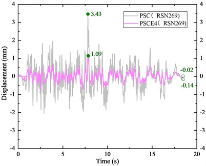
a) RSN269
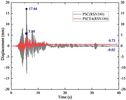
b) RSN180
Furthermore, to investigate how various types of earthquake motion affect the vibration absorption capability of energy dissipation bars, the discrepancies in the average maximum displacement response and residual displacement of the pier's top after an earthquake were compared across three different types of earthquake motions, as illustrated in Fig. 15.
Fig. 15Comparison of the average seismic response values of piers subjected to various types of earthquake motions
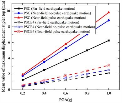
a) Mean value of maximum displacement at the top of the pier
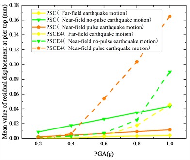
b) Mean value of residual displacement at the top of the pier
According to the analysis presented in Fig. 15(a), when subjected to seismic activity, the maximum displacement at the top of the pier for PSCE4 is notably lower than PSC. The efficiency of vibration absorption becomes more pronounced as the Peak Ground Acceleration (PGA) increases. For instance, during a 1.0 g near-field pulse earthquake, the energy dissipation bar exhibits a 68 % absorption rate due to the significant swing of the pier under intense seismic conditions. The plastic deformation of the energy dissipation bar aids in dissipating the seismic energy input to the pier. Moreover, the proximity of the earthquake's epicenter amplifies the maximum displacement at the pier top, with the near-field pulse earthquake causing the greatest displacement compared to other types of seismic motions. The disparity in displacement becomes more significant with higher PGAs. For instance, in the case of PSC, at 0.2 g, there is a 0.68 mm variation in maximum displacement, while at 1.0 g, this difference increases to 3.56 mm.
Based on the analysis presented in Fig. 15(b), as the peak ground acceleration (PGA) continues to rise, the average residual displacement of PSCE4 surpasses that of PSC. This trend is observed across various seismic scenarios, including near-field seismic events with pulse (0.4 g-1.0 g) and without pulse (1.0 g), as well as far-field seismic events (0.6 g-1.0 g). This observation can be attributed to the behavior of the energy dissipation bar. In the presence of minor seismic activities, the energy dissipation bar predominantly maintains its elasticity, thereby mitigating displacement responses at the pier's apex and offering elastic resilience to the structure. Conversely, during intense seismic events, substantial plastic deformation of the energy dissipation bar indirectly contributes to increased residual deformation in the pier post-earthquake. Furthermore, it is noted that the average residual displacement of piers subjected to near-field seismic motions exceeds that of those under far-field motions, with a more pronounced effect as PGA values escalate.
5. Conclusions
To improve the seismic safety of segmentally assembled round-end hollow piers in high-speed railways located in high-intensity earthquake zones, this study investigates the influence of energy dissipation bars on their seismic performance. The key findings are summarized as follows:
1) Effect of diameter and quantity: The diameter of the energy dissipation bars ranges from 10 mm to 35 mm (corresponding to a section contribution rate of 0.09 %-1.15 %). Within this range, the pier’s horizontal resistance increases by up to 2.05 times, loading stiffness by 2.7 times, unloading stiffness by 2.84 times, and energy dissipation per cycle by 6.69 times. Varying the number of bars from 2 to 12 (with a section contribution rate of 0.15 %-0.88 %) increases horizontal resistance by 1.70 times, loading stiffness by 2.35 times, unloading stiffness by 2.18 times, and energy dissipation per cycle by 3.88 times.
2) Effect of bar arrangement: Altering the arrangement of energy dissipation bars has a limited impact on seismic performance compared to changing their diameter or quantity. Notably, placing the bars outside the post-cast section of the pier results in better seismic performance than placing them inside.
3) Residual displacement control: Parametric analysis shows that the residual displacement angle of the pier is influenced by the energy dissipation bars. Proper selection of the main design parameters should be based on the target seismic displacement of the pier. In some scenarios studied, residual displacement may exceed the set limits, highlighting the importance of careful parameter definition.
4) Seismic vibration absorption: As peak ground acceleration (PGA) increases, the rocking amplitude of the pier increases, and the energy dissipation bars deform synergistically, enhancing vibration absorption, with potential rates exceeding 60 %. However, under severe earthquake conditions, the bars may experience extensive plastic deformation or damage, which indirectly increases post-earthquake residual displacement of the pier.
5) Near-field earthquake effects: The pier’s seismic response is more pronounced under near-field earthquakes than far-field events. In particular, the top displacement of the pier is significantly influenced by near-field pulse motion, which should be carefully considered in design.
6) Applicability and limitations: The conclusions are primarily applicable to round-end hollow piers with similar shear-span ratios. Caution should be exercised when extending the findings to other structural types. Future research involving different pier configurations and larger-scale specimens is recommended to further validate the results.
6. Future research and extension
In western China, the terrain is mountainous and rivers are abundant. For slender railway bridge piers, round-end hollow piers are commonly adopted as substructures, particularly in projects such as the Sichuan-Tibet Railway. To improve construction efficiency, prestressed, segmental, prefabricated hollow piers have been increasingly applied in railway bridge projects in this region. However, as many areas intersect active seismic zones, potential seismic safety concerns remain.
In this study, energy-dissipating steel bars were incorporated into the prestressed segmental hollow piers, and their design parameters were adjusted to significantly enhance the seismic performance and post-earthquake self-centering ability of the piers. This demonstrates that the combination of prefabricated segmental piers with energy-dissipating steel not only improves construction efficiency and quality control but also strengthens seismic safety and post-earthquake resilience in high-intensity seismic regions, offering substantial engineering value.
Previous studies [41-42] have shown that seismic isolation devices – such as high-damping rubber bearings (HDRB), lead-rubber bearings (LRB), and friction pendulum systems (FPS) – as well as viscous dampers and magnetorheological (MR) semi-active dampers can effectively reduce base shear and deck acceleration of bridges under seismic excitation. However, the prestressed segmental hollow piers investigated in this study exhibit rocking-type behavior under seismic action, and their failure modes are primarily associated with prestress loss or joint cracking and misalignment, which differ markedly from the behavior and failure mechanisms of conventional monolithic piers. This indicates that the seismic response of segmental hollow piers is distinct from traditional piers, and directly applying seismic isolation or damping devices designed for conventional piers may result in uncertain mitigation effects.
Therefore, future research should further explore the synergistic application of prefabricated segmental piers with seismic isolation devices and dampers. By considering the unique behavior of segmental piers, the optimal combination of these devices can be investigated, critical design parameters can be identified, and more controllable and efficient seismic mitigation strategies can be developed, providing theoretical guidance and engineering support for the design and construction of high-speed railway bridges.
References
-
J. T. Hewes and M. J. N. Priestley, “Seismic design and performance of precast concrete segmental bridge columns,” University of California, San Diego, 2002.
-
J. Ge, X. Yan, and Z. Wang, “Seismic performance analysis of two-segment bridge columns with prestressing bars,” (in Chinese), Journal of Railway Science and Engineering, Vol. 14, No. 11, pp. 2390–2398, 2017.
-
Z. Bu and W. Wu, “Experiment on seismic behavior of precast segmental concrete bridge piers under quasi static cyclic loading,” (in Chinese), Journal of Architecture and Civil Engineering, Vol. 32, No. 1, pp. 42–50, 2015.
-
Y. Zhang, G. Wu, Z. Sun, and G. Teng, “Analysis of seismic performance of a hybrid prefabricated bridge pier system,” (in Chinese), Journal of Chang’an University (Natural Science Edition), Vol. 39, No. 1, pp. 70–80, 2019.
-
J. Jia, J. Zhao, Q. Zhang, L. Qi, Q. Han, and X. Du, “Experimental on lateral bearing behavior of post-tensioned segmental CFST bridge pier columns,” (in Chinese), China Journal of Highway and Transport, Vol. 30, No. 3, pp. 236–245, 2017.
-
C.-C. Chou and Y.-C. Chen, “Cyclic tests of post-tensioned precast CFT segmental bridge columns with unbonded strands,” Earthquake Engineering and Structural Dynamics, Vol. 35, No. 2, pp. 159–175, Jan. 2005, https://doi.org/10.1002/eqe.512
-
J. B. Mander and C. T. Cheng, “Seismic resistance of bridge piers based on damage avoidance design,” No. NCEER-97-0014, State University of New York, Buffalo, NY, 1997.
-
S. Liu, “Research on improvement measures for seismic performance of precast segmental bridge column,” (in Chinese), Dalian University of Technology, 2016.
-
M. Jiang, “Research and improvement on seismic performance of precast segmental concrete-filled tube bridge piers,” (in Chinese), Beijing Jiaotong University, 2018.
-
J. Mo, X. Ma, J. Zhang, and J. Li, “Pseudo static test of UHPC connecting segment assembled pier,” (in Chinese), Structural Engineers, Vol. 34, No. S1, pp. 88–95, 2018.
-
Z. Wang, “Research on seismic performance and design method of self-centering precast segmental UHPC hollow bridge piers,” (in Chinese), Southeast University, 2018.
-
S. Ichikawa, H. Matsuzaki, A. Moustafa, M. A. Elgawady, and K. Kawashima, “Seismic-resistant bridge columns with ultrahigh-performance concrete segments,” Journal of Bridge Engineering, Vol. 21, No. 9, p. 04016049, Sep. 2016, https://doi.org/10.1061/(asce)be.1943-5592.0000898
-
S. Li, T. Zhao, M. S. Alam, Z. Cheng, and J.-Q. Wang, “Probabilistic seismic vulnerability and loss assessment of a seismic resistance bridge system with post-tensioning precast segmental ultra-high performance concrete bridge columns,” Engineering Structures, Vol. 225, p. 111321, Dec. 2020, https://doi.org/10.1016/j.engstruct.2020.111321
-
Y. Ma and Y. Zhang, “Effect of CFRP sheets on seismic performance of precast segmental piers,” (in Chinese), China Earthquake Engineering Journal, Vol. 42, No. 4, pp. 847–855, 2020.
-
M. Elgawady, A. J. Booker, and H. M. Dawood, “Seismic behavior of posttensioned concrete-filled fiber tubes,” Journal of Composites for Construction, Vol. 14, No. 5, pp. 616–628, Oct. 2010, https://doi.org/10.1061/(asce)cc.1943-5614.0000107
-
M. A. Elgawady and H. M. Dawood, “Analysis of segmental piers consisted of concrete filled FRP tubes,” Engineering Structures, Vol. 38, pp. 142–152, May 2012, https://doi.org/10.1016/j.engstruct.2012.01.001
-
S. Motaref, M. S. Saiidi, and D. Sanders, “Shake table studies of energy-dissipating segmental bridge columns,” Journal of Bridge Engineering, Vol. 19, No. 2, pp. 186–199, Feb. 2014, https://doi.org/10.1061/(asce)be.1943-5592.0000518
-
Z. Xue, “Experimental research on CFRP reinforcement of bridge piers with precast segments,” (in Chinese), Qingdao University of Technology, 2021.
-
W. Trono, G. Jen, M. Panagiotou, M. Schoettler, and C. P. Ostertag, “Seismic response of a damage-resistant recentering posttensioned-HYFRC bridge column,” Journal of Bridge Engineering, Vol. 20, No. 7, p. 04014, Jul. 2015, https://doi.org/10.1061/(asce)be.1943-5592.0000692
-
J. Gu, J. Zhang, and D. Liu, “Research progress on damping and energy dissipation structures of Precast Segmental Concrete Piers,” (in Chinese), Journal of China and Foreign Highway, Vol. 37, No. 5, pp. 183–187, 2017.
-
L. Yan, L. Qinghe, L. Xiaoyong, C. Yang, and Z. Hao, “Seismic resistance capacity of applying PSBC in high-speed railway bridge,” (in Chinese), Journal of Railway Science and Engineering, Vol. 19, No. 6, pp. 1492–1501, 2022.
-
C. Zhongkui, W. Zhenyu, and Y. Zhen, “Seismic performance of precast segmental bridge columns reinforced with high-strength steel bars,” (in Chinese), Journal of Nanjing University of Technology (Natural Science Edition), Vol. 42, No. 3, pp. 312–318, 2020.
-
C. Zhong-Kui, “Seismic performance and design method of hybrid reinforced precast segmental bridge columns,” (in Chinese), Harbin Institute of technology, 2018.
-
Z. Weiding, “Hysteretic energy dissipation and seismic resiliency of precast piers with high-strength bar,” (in Chinese), Southeast University, 2019.
-
Y.C. Ou, M.S. Tsai, K.C. Chang, and G. C. Lee, “Cyclic behavior of precast segmental concrete bridge columns with high performance or conventional steel reinforcing bars as energy dissipation bars,” Earthquake Engineering and Structural Dynamics, Vol. 39, No. 11, pp. 1181–1198, Jan. 2010, https://doi.org/10.1002/eqe.986
-
W. Y. Kam, S. Pampanin, A. Palermo, and A. J. Carr, “Self‐centering structural systems with combination of hysteretic and viscous energy dissipations,” Earthquake Engineering and Structural Dynamics, Vol. 39, No. 10, pp. 1083–1108, Jul. 2010, https://doi.org/10.1002/eqe.983
-
Z. Tan, “Seismic performance of post-tensioned precast concrete segmental bridge columns with viscoelastic dampers,” (in Chinese), Harbin Institute of technology, 2013.
-
H. Gao, “Seismic performance of self-centering segment bridge piers with external viscoelastic dampers,” (in Chinese), Harbin Institute of technology, 2016.
-
X. Liu, “Seismic performance analysis on the segmental concrete filled steel tube piers with replaceable energy dissipation devices,” (in Chinese), Qingdao University of Technology, 2021.
-
J. Zhao, X. Liu, Q. Meng, and X. Li, “Seismic performance of precast segmental CFST bridge piers with external replaceable energy dissipation devices,” (in Chinese), Journal of Southwest Jiaotong University, Vol. 57, No. 5, pp. 1113–1121, 1145, 2021.
-
D. Marriott, S. Pampanin, and A. Palermo, “Quasi‐static and pseudo‐dynamic testing of unbonded post‐tensioned rocking bridge piers with external replaceable dissipaters,” Earthquake Engineering and Structural Dynamics, Vol. 38, No. 3, pp. 331–354, Nov. 2008, https://doi.org/10.1002/eqe.857
-
D. Marriott, S. Pampanin, and A. Palermo, “Biaxial testing of unbonded post‐tensioned rocking bridge piers with external replacable dissipaters,” Earthquake Engineering and Structural Dynamics, Vol. 40, No. 15, pp. 1723–1741, Apr. 2011, https://doi.org/10.1002/eqe.1112
-
Y. Song, “Research on seismic performance of segmental bridge pires with external energy-dissipation plates,” (in Chinese), Southeast University, 2018.
-
F. Zhang, “Structural improvement and seismic performance analysis of precast-assembled concrete-filled steel tube pier,” (in Chinese), Chang’an University, 2019.
-
D. Y. Moon, H. Roh, and G. P. Cimellaro, “Seismic performance of segmental rocking columns connected with NiTi martensitic SMA bars,” Advances in Structural Engineering, Vol. 18, No. 4, pp. 571–584, Nov. 2016, https://doi.org/10.1260/1369-4332.18.4.571
-
S. Varela, “A bridge column with super elastic NiTi SMA and replaceable rubber hinge for earthquake damage mitigation,” Smart Materials and Structures, Vol. 25, No. 7, p. 075012, 2016.
-
T. Guo, Z. Cao, Z. Xu, and S. Lu, “Cyclic load tests on self-centering concrete pier with external dissipators and enhanced durability,” Journal of Structural Engineering, Vol. 142, No. 1, p. 04015, Jan. 2016, https://doi.org/10.1061/(asce)st.1943-541x.0001357
-
S. Hashimoto, Y. Fujino, and M. Abe, “Damage analysis of Hanshin expressway viaducts during 1995 Kobe earthquake. II: Damage mode of single reinforced concrete piers,” Journal of Bridge Engineering, Vol. 10, No. 1, pp. 54–60, Jan. 2005, https://doi.org/10.1061/(asce)1084-0702(2005)10:1(54)
-
K. Kawashima, G. A. Macrae, J.-I. Hoshikuma, and K. Nagaya, “Residual displacement response spectrum,” Journal of Structural Engineering, Vol. 124, No. 5, pp. 523–530, May 1998, https://doi.org/10.1061/(asce)0733-9445(1998)124:5(523)
-
Z. Li, “Experimental and numerical analysis study on seismic performance of segmental assembled round end hollow piers,” (in Chinese), Beijing Jiaotong University, 2021.
-
B. B. Soneji and R. S. Jangid, “Effectiveness of seismic isolation for cable-stayed bridges,” International Journal of Structural Stability and Dynamics, Vol. 6, No. 1, pp. 77–96, Nov. 2011, https://doi.org/10.1142/s0219455406001836
-
S. N. Madhekar and R. S. Jangid, “Variable dampers for earthquake protection of benchmark highway bridges,” Smart Materials and Structures, Vol. 18, No. 11, p. 115011, Nov. 2009, https://doi.org/10.1088/0964-1726/18/11/115011
About this article

This research is funded by the National Natural Science Foundation under the project “Research on the Mechanisms of Catastrophic Events and State Control Methods for High-Speed Rail Lines under Near-Fault Strong Earthquake Effects”, with project number U2368210.
The datasets generated during and/or analyzed during the current study are available from the corresponding author on reasonable request.
S. Pengfei was responsible for developing the research approach, creating and computing the finite element model, as well as data processing and analysis. H. Guo validated the accuracy of the finite element model and verified the data. W. Wang contributed to the creation of figures and tables, as well as literature research. L. Hao wrote the literature review and organized the documents. All authors have read and agreed to the published version of the manuscript.
The authors declare that they have no conflict of interest.
