Abstract
The face teeth of wheel hub bearing are manufactured using a two-step rotary riveting forming process. Controlling the forming force and improving the tooth profile fullness are critical, as these factors directly affect bearing performance. This study employs DEFORM finite element simulation combined with experimental verification to analyze the influence of structural and process parameters – including blank dimensions, pre-riveting state, feed rate, spindle rotation speed, and riveting inclination angle – on the forming force and tooth profile fullness. Optimal structural and process parameters are thereby determined. The results indicate that among blank structural parameters, wall thickness has the greatest impact on tooth profile fullness, followed by inner corner radius, with outer corner radius having the least effect. Optimized blank dimensions improve profile fullness and reduce forming force. The pre-riveting state significantly influences the tooth forming process, a fully riveted state reduces axial forming force by 24.9 % compared to a non-riveted state and markedly improves profile fullness. A smaller feed rate and higher spindle speed reduce forming force and improve profile fullness, but may cause flash at the tooth outer edge. Conversely, excessive feed rate and low spindle speed reduce profile fullness. Experimental verification shows that optimized process parameters increase tooth profile fullness by 4.6 % to 96.2 % and reduce forming force by 17.8 % compared to pre-optimization conditions, confirming the effectiveness of the parameter optimization.
Highlights
- Among blank structural parameters, wall thickness most significantly affects profile fullness, followed by inner corner radius; outer fillet radius has the least effect.
- Pre-riveting state has a significant impact on tooth rotary riveting forming, a fully riveted state reduces axial forming force by 24.9% and improves tooth profile fullness.
- The feed rate, spindle speed, and inclination angles all have an impact on fullness. The optimal combination is a feed rate of 2 mm/s, a spindle speed of 600 rpm, and a inclination angles of 17.5°.
- Experimental results confirm that optimized parameters increase tooth profile fullness by 4.6% to 96.2% and reduce forming force by 4.6% compared to pre-optimization conditions.
1. Introduction
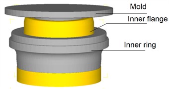
New energy vehicles, characterized by large starting torque and high acceleration, impose higher requirements on the performance of wheel hub bearings. The new type of wheel hub bearing adopts an inner flange shaft face tooth structure (Fig. 1), which achieves pre-tightening and torque transmission by riveting the face teeth onto the inner ring. The integrated design reduces weight by 10 % and enhances load capacity by over 30 %. However, this special structure poses challenges to manufacturing. Machining methods such as gear milling and grinding are not suitable for processing the bearing face teeth after assembly due to cutting fluid issues. Thermal processing is inappropriate because the bearing is internally filled with grease, and cold precision forging is also infeasible, as excessive forming force will damage the assembly performance of the bearing. Rotary riveting, due to its low forming force and significant advantage in local continuous forming, emerges as the preferred solution. However, due to structural constraints, it is challenging to directly form the face teeth through one-step rotary riveting. Achieving high-performance manufacturing of face teeth remains a current research challenge. To address this, this paper proposes a two-step rotary riveting process to efficiently form the face teeth of wheel hub bearings.
The first step forming employs a smooth cavity mold to achieve flanging riveting between the inner flange and the inner ring, forming a flat surface and providing preliminary pre-tightening of the hub bearing. The second step forming uses a tooth shaped mold to perform locally rotary riveting on the pre-riveted surface, generating the face teeth and achieving precise pre-tightening of the bearing. Research on the two-step rotary riveting process remains limited. The author’s team has previously investigated the principle and basic characteristics of this process, verifying its feasibility [1]. However, issues such as tooth profile fullness and the influence of process parameters require further study.
Fig. 1Wheel hub bearing with face teeth
Existing research has extensively covered single-step rotary riveting forming. Zhuang [2] elucidated key issues in the cold rotary forging process, such as stress distribution, strain distribution, and tooth accuracy of spur bevel gears. Gu [3] studied the effects of inclination angle, temperature, and feed rate on the riveting forming of aluminum alloy thin-walled mobile phone shell frames. Hua [4] proposed a cold rotary forging method for gear rack forming, identifying interference conditions between the upper mold and gear rack, optimizing parameters to avoid interference, and achieving multi-tooth profile forming with a single mold set. Zhu [5] introduced a two-step forming method to achieve the flanging of circular holes in flat billets, the first step uses edge constrained coreless spinning to bend the edges, and the second step uses a die and a stamping roller to reduce the thickness by spinning and ensure the accuracy of the hole contour. Jin [6] proposed a process optimization method for cold rotary forging of deep and narrow width components, identifying horizontal stress imbalance as a main cause of workpieces stress uneven, and suggesting a metal flow control scheme to balance stress. Yu [7-8] used Deform software to establish a 3 D rigid-plastic numerical model of double roll riveting for circular workpieces, studied stress and velocity field distributions as well as the effects of mold preheating and initial workpiece size on deformation uniformity and maximum axial load. Wang [9] combined simulation and experiment to study the deformation characteristics and microstructure evolution of GH4169 alloy under axial upsetting and riveting process. Lacopo [10] studied asymmetric spinning, quantifying part asymmetry via planar contour curvature range and verifying the hypothesis that the planar curvature range can predict the probability of workpiece failure, finding that increased asymmetry only slightly affects formable height. Bouragba [11] used reverse analysis to calibrate the parameters of a coupled GTN damage-hardening constitutive model, applying it to deep drawing simulation of the handcart tray, the results showed that the model can more accurately predict the initiation of wrinkling and necking defects during the deep drawing process, significantly improving the defect prediction ability compared to traditional methods.
In the field of wheel hub bearing rotary riveting, Xiong [12-13] conducted the research on third-generation hub bearing rotary riveting process, analyzed the influence of blank structure on forming shape, and carried out research on riveting parameter optimization and inner ring expansion, proposed a measurement method of riveting pre-tightening force of bearing based on strain measurement, turning and riveting, and simulation correction. Li [14] used a micro laser sensor to monitor axial displacement of the bearing during the flanging and riveting process online, indirectly controlling bearing clearance, indicated a pre-tightening force of 38.8 kN. Suk [15] performed implicit elastic-plastic finite element analysis on hub bearing flanging riveting using multi-body functions, finding that during the homogenization stage, both inner rings share the load, and the residual stress field exhibits axisymmetric characteristics, developing into two zones with the cavity as the boundary.
This paper uses finite element numerical simulation to analyze the influence of blank structural parameters, pre-riveting state, and process parameters on the face tooth forming, aiming to address issues of tooth filling fullness, high forming force and the influence law of process parameters, the optimized process parameters are obtained, and the feasibility of the parameters is verified through experiments, laying the foundation for its industrial application.
2. FE model of two step rotary riveting of hub bearing face tooth
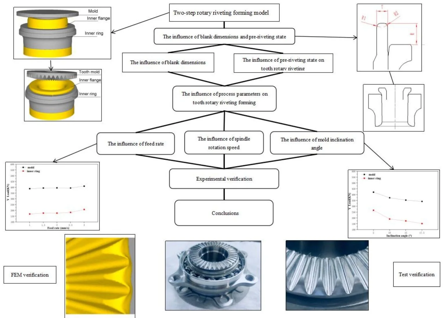
Since this two-step rotary riveting and rolling plastic forming process mainly involves the inner flange, the inner ring, and the riveting head, structures far from the shaft end and other components with negligible influence are ignored. Therefore, only these three effective parts are selected for modeling and then imported into DEFORM for simulation analysis. This process falls within the scope of rotary riveting and rolling, with a friction coefficient of 0.12 and a simulated temperature of 20 ℃. For the motion of the inner flange under the boundary constraints of the model, the inner flange must remain fixed during the two-step rotary riveting and rolling simulation. Fixed constraints in the , , and directions are applied to the bottom surface of the inner flange, and its velocity in all directions is defined as zero.
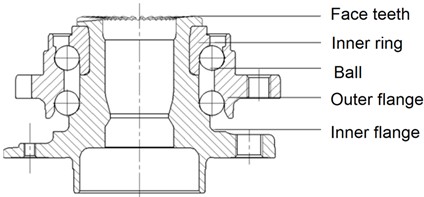
After simplifying the bearing inner race, a three-dimensional model was established and imported into the DEFORM-3D software. First, the first-step rotary riveting simulation was carried out (Fig. 2(a)). In the second step, the die was replaced with a tooth-shaped die to perform rotary riveting for forming the face teeth (Fig. 2(b)). Both the die and the inner race in the model were set as rigid bodies. The absolute meshing method was used to locally refine the mesh in the tooth forming region, with a minimum mesh size of 0.8 mm and a size ratio of 4. To improve the accuracy and efficiency of the simulation, the DEFORM remeshing technology was adopted.
Fig. 2FE model of two step rotary riveting for face tooth
a) First step rotary riveting
b) Second step rotary riveting
The inner flange material is 65 Mn, with Young’s modulus of 212 GPa, and Poisson’s ratio is 0.288. Based on material tensile test, the parameters of the J-C constitutive model obtained through fitting are: 530 MPa, 1635, 0.59445, and 0.01434. Therefore, the Johnson-Cook (J-C) constitutive model is adopted as follows:
3. The influence of blank dimensions and pre-riveting state
3.1. The influence of blank dimensions
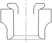
The blank structure is characterized by four parameters: wall thickness , height , inner corner radius , and outer corner radius , as shown in Fig. 3. Based on the design and previous manufacturing experience, the height H affects the outer diameter after riveting and should be optimized within the range of 11.5-12.5 mm. The thickness influences the riveting height and the overall assembly height of the bearing, and should be selected within 6.5-7.5 mm. affects the initial contact position between the pre-riveting mold and the workpiece, thereby influencing the pre-riveting shape, and should be within 1.5-3.5 mm. affects the fullness of the tooth profile at the outer diameter and should be within 1-3 mm. A 4 factor- 3 level orthogonal design scheme is used for two step forming simulation, as shown in Table 1. The first-step mold descent displacement is fixed cross schemes, resulting in different pre-riveting outer diameters. In the second step, simulation steps with identical face tooth outer diameters are selected for analysis, meaning mold descent displacement varies per scheme.
Fig. 3Blank structure dimensions
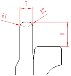
Table 1Simulation scheme and results
No. | / mm | / mm | / mm | / mm | Profile fullness | Forming force / kN | Comprehensive score |
1 | 11.5 | 6.5 | 3.5 | 2 | 90.1 % | 282 | 0.000 |
2 | 11.5 | 7 | 1.5 | 1 | 91.2 % | 375 | 0.423 |
3 | 11.5 | 7.5 | 2.5 | 3 | 90.4 % | 407 | 0.394 |
4 | 12 | 6.5 | 1.5 | 3 | 93.8 % | 324 | 0.664 |
5 | 12 | 7 | 2.5 | 2 | 92.4 % | 336 | 0.491 |
6 | 12 | 7.5 | 3.5 | 1 | 94.5 % | 370 | 0.896 |
7 | 12.5 | 6.5 | 2.5 | 1 | 90.7 % | 328 | 0.217 |
8 | 12.5 | 7 | 3.5 | 3 | 93.2 % | 301 | 0.511 |
9 | 12.5 | 7.5 | 1.5 | 2 | 93.0 % | 405 | 0.773 |
K1 | 0.817 | 0.882 | 1.860 | 1.537 | |||
K2 | 2.052 | 1.425 | 1.103 | 1.264 | |||
K3 | 1.501 | 2.064 | 1.408 | 1.570 | |||
Range | 1.234 | 1.182 | 0.757 | 0.306 |
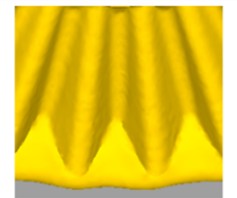
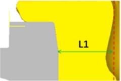
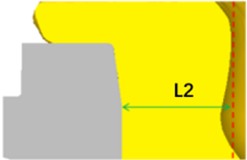
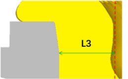
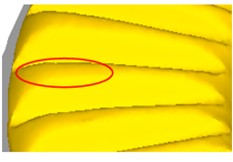
Excessive forming force can cause deformation of the hub bearing, leading to expansion or cracking of the inner race, thereby affecting bearing clearance and preload, and ultimately impairing its service performance. Therefore, reducing the forming force is one of the core optimization objectives. Meanwhile, tooth profile fullness affects torque transmission capacity, and improving tooth profile fullness is another optimization objective. Tooth profile fullness should be the ratio of the actual volume of the formed tooth profile to the theoretical volume, but for a more intuitive comparison, the tooth profile fullness is now defined as the ratio of the actual cross-sectional area to the ideal cross-sectional area after forming (as shown in Fig. 4). Insufficient forming usually occurs at the outer diameter tooth top.
Fig. 4Schematic diagram of profile fullness
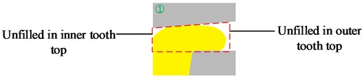
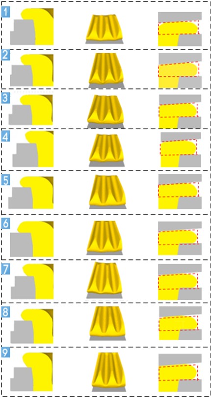
Fig. 5(right) shows tooth filling fullness for different blank designs. It can be seen that, while keeping the outer diameter of the face tooth unchanged, scheme 6 exhibits the best filling fullness (fullness 94.5 %,) scheme 1 shows the worst filling fullness (fullness 90.1 %). According to the range analysis method, the wall height most significantly affects profile fullness, followed by the inner fillet , outer fillet radius has the least impact. Larger blank wall thickness and smaller inner corner radius can effectively improve tooth filling integrity. The optimal profile fullness corresponds to factor levels 2-3-1-3.
Fig. 5Simulation result: from left pre-riveting, tooth profile, fullness
Similarly, range analysis shows that wall thickness most affects forming force, followed by inner corner radius R1, and height has the least effect. A smaller wall thickness and larger inner corner radius can reduce forming force. The best fullness is achieved at factor levels 2-1-3-2.
In order to simultaneously analyze the forming force and tooth filling fullness, the weight method and comprehensive score were used to analyze the data. Convert the two indicators into membership value and calculate comprehensive score using the following method:
– Membership = (indicator value – minimum of indicator value)/Range of indicator value.
– Comprehensive score = weight1 * Membership1+ weight 2 * Membership 2.
According to production experience, tooth profile fullness is an important quality indicator of products, forming force mainly affects energy consumption, so tooth profile fullness is more important than forming force. Therefore, in the analysis, the weight of fullness is 0.65 and the weight of forming force is 0.35. The comprehensive score calculation results are listed in the rightmost column of Table 1. Range analysis is performed based on the comprehensive score calculation, the values of , , , and range are listed in Table 1. It can be seen that the most reasonable level of each factor is 2-3-1-3, which means 12 mm, 7.5 mm, 1.5 mm, 3 mm. The result is consistent with the analysis results when considering the fullness separately. H is the most significant influencing factor, followed by , the results are slightly different from those obtained when analyzing fullness separately.
3.2. The influence of pre-riveting state on tooth rotary riveting
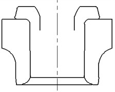
The first step riveting state influences the second step forming. Three pre-riveting states – un-riveted, lightly pre-riveted and fully pre-riveted (Fig. 6) – are used to analyze the influence. These states are obtained by selecting appropriate simulation steps from first-step results as initial conditions for the second step.
Fig. 6Three pre-riveting states
a) Un-riveted
b) Lightly pre-riveted
c) Fully pre-riveted
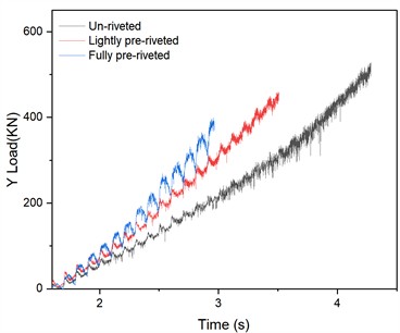
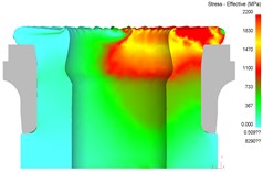
Fig. 7 shows axial forming force variation over time for the three pre-riveting states. It can be seen that axial forces decrease progressively from un-riveted to fully pre-riveted states. This is because un-riveted state requires a greater mold displacement and time to complete the face tooth forming, and a greater deformation of the workpiece, resulting in a higher forming force. The maximum axial forming force on mold decreases from 526 kN (un-riveted) to 395 kN (fully pre-riveted), a 24.9 % reduction. On the other hand, in the un-riveted state, the process time is long, the increase in force is gentle (the black curve has a smaller slope), while in the full pre-riveted state, the increase in force is severe (the blue curve has a large slope). This is because, the contact area between the mold and the workpiece at the beginning of the process is the smallest on the un-riveted state, while the contact area is the largest in the full pre riveted state.
Fig. 7The axial force of different riveting states
The difference in stress during the forming process for the three pre-riveting states is mainly in the early stage of process, and there is basically no difference in stress characteristics in the middle and later stages of forming process. Fig. 8 shows the stress evolution process during the forming process in the un riveted state. It can be seen that, the mold comes into partial contact with the workpiece at the beginning, and the stress is mainly distributed on the surface of the workpiece, with the maximum stress area (plastic deformation area) being relatively small, the stress distribution expands in both radial and circumferential directions. As the mold descends, the contact area between the mold and the workpiece gradually increases, the teeth gradually form, and the maximum stress area gradually expands. At the same time, the maximum stress depth gradually increases in the height direction (axial direction) of the workpiece.
Fig. 8Effective stress distribution of un-riveted state
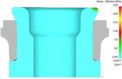
a) Beginning of process
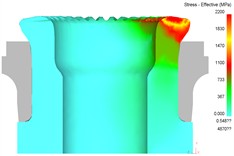
b) Mid of process
c) End of process
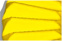
Fig. 9 shows tooth profile fullness under different pre-riveting states. Un-riveted state yields incomplete outer tooth filling with slight concavity (fullness 91.2 %), Lightly pre-riveted state improves fullness to 92.7 %. Fully pre-riveted state achieves the best fullness (93.4 %), though a small unfilled area remains at the tooth outer edge.
Fig. 9Tooth fullness under different pre-riveting state
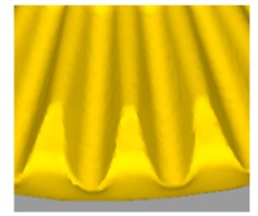
a) Under un-riveted
b) Under lightly pre-riveted
c) Under fully pre-riveted
Furthermore, as shown in Fig. 10, the pre-riveting state has a significant impact on the radial expansion and upsetting of the material. Under un-riveted state, in the initial stage of forming, the inner flange and inner ring have not been riveted together, the inner ring has not formed a constraint on the radial outward expansion of the material, at this time, the deformation of the material is mainly due to the flanging effect, and the upsetting effect is weak (Fig. 10(a)). Under lightly pre-riveted state, the round corner of the inner ring forms a certain constraint on the radial expansion of the flange by the first step forming, and the flange has applied partial pre-tightening force to the inner ring, which lead the material to flow towards the center and enhance upsetting effect (Fig. 10(b)). Under the fully pre-riveted state, the inner flange has been riveted with inner ring by the first step riveting, the inner flange material is subjected to stronger axial compression in the second step forming, and the degree of upsetting is significantly enhanced, the material can fill the mold cavity well, and the profile of the tooth top and root is clear. As the pre-riveted state transitions from “un riveted” to “fully pre-riveted”, the upsetting effect of deformation gradually increases, reflected by in the Fig. 10.
Fig. 10Upsetting under different pre-riveted states
a) Under un-riveted
b) Under lightly pre-riveted
c) Under fully pre-riveted
4. The influence of process parameters on tooth rotary riveting forming
4.1. The influence of feed rate
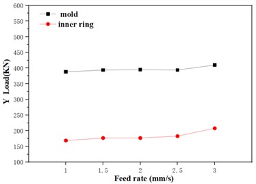
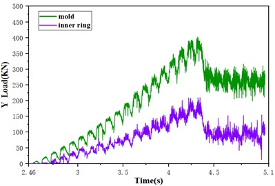
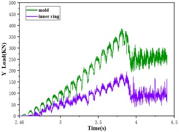
With constant spindle speed and other parameters, simulations were conducted at mold feed rates of 1, 1.5, 2, 2.5, and 3 mm/s. Fig. 10 shows axial forming force variation with feed rate. As feed rate increases, axial forces on mold and inner ring rise slightly. Maximum axial forming force increases on mold from 388 kN at 1 mm/s to 410 kN at 3 mm/s, with a rise of 5.6 %, while the maximum axial force on the inner ring increases from 169 kN to 208 kN, with a rise of 23.07 %. The effect of feed rate on the axial force is more significant on the inner ring than on the mold. As a sample, Fig. 11 shown the forming force under 1.5 mm/s feed rate, where force drops sharply after 3.8 s due to the finishing stage.
Fig. 11Influence of feed rate on forming force
a) Forming force under different feed rates
b) Forming force under 1.5 mm/s feed rate
Fig. 12Tooth profile fullness at different feed rate
a) At 1mm/s
b) At 1.5 mm/s
c) At 2 mm/s
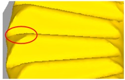
d) At 2.5 mm/s
e) At 3 mm/s
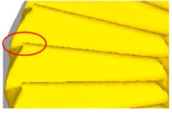
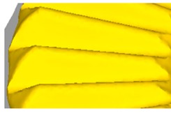
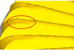
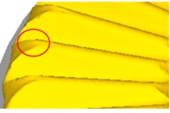
As shown in Fig. 12, The filling degree of the tooth profile also changes with the feed rate, and flash is generated. To ensure that the performance of the product is not significantly affected, the flash should be less than 1.200 mm. At 1 mm/s, the filling fullness is high (94.7 %), but flash occurs at the tooth outer edge (0.174-0.212 mm). At 2 mm/s, fullness slightly decreases but remains acceptable without flash. At 2.5 and 3 mm/s, unfilled areas enlarge, with 3 mm/s yielding 92.3 % fullness. Thus, higher feed rates reduce profile fullness. Considering both forming force and fullness, a feed rate of 1.5-2 mm/s is optimal.
4.2. The influence of spindle rotation speed
With constant feed rate and other parameters, simulations used spindle speeds of 150, 300, 450, 600, and 750 rpm to analyze their effects on the forming force and tooth profile fullness. Fig. 13 shows forming force variation with speed. It can be seen that as the spindle rotation speed increases, the axial force acting on the mold and inner ring gradually decreases. It is because as the rotation speed increases, the relative feed rate per rotation decreases, the total deformation decreases, and the deformation resistance during forming decreases, therefore, the axial force acting on the mold and inner ring shows a decreasing trend. The maximum axial force of the mold decreased from 584.5 kN at 150 rpm to 370 kN at 750 rpm, with a reduction of 36.69 %. The maximum axial force of the inner ring decreased from 286.7 kN to 171.6 kN, with a reduction of 40.12 %. The change of rotation speed has a more significant impact on the axial force of the inner ring than that of the mold. Fig. 13(b) shows the forming force at 750 rpm.
Fig. 13The influence of rotation speed on forming force
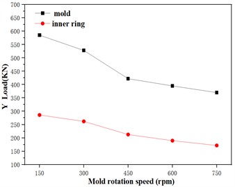
a) Forming force at different rotation speed
b) Forming force at 750 rpm
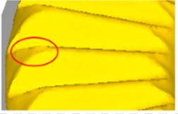
Fig. 14Profile fullness under different rotation speed
a) At 150 rpm
b) At 300 rpm

c) At 450 rpm
d) At 600 rpm
e) At 750 rpm
As shown in Fig. 14, tooth profile fullness varies with speeds. At 150 rpm, about half of the tooth length at top of the tooth is not completely filled, at 300 rpm, there is still a small area of incomplete filling at the outer of the tooth profile, at 750 rpm, it causes the filling of the tooth to overflow and produce burrs and flash (0.382-0.659 mm), at 450 rpm and 600 rpm, fullness is better without flash. Considering both fullness and forming force, 600 rpm is suitable.
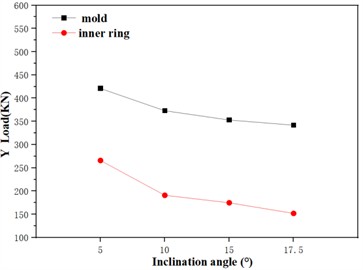
4.3. The influence of mold inclination angle
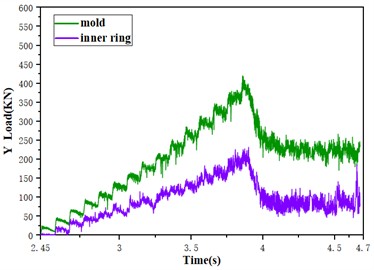
The riveting inclination angle is an important indicator of the machine, which has a significant impact on the quality and efficiency of the rotary riveting process. Inclination angles of 5°, 10°, 15°, and 17.5° were analyzed. Fig. 15 shows the axial forming force of the mold and inner ring at different riveting inclination angles. Smaller inclination angle increase axial force due to larger mold-workpiece contact area and greater material deformation. Thus, larger inclination angles are advantageous. Fig. 15(b) shown the forming force at inclination angle 15°.
Fig. 15Influence of inclination angle on forming force
a) Forming force under different inclination angle
b) Forming force at inclination angle 15°
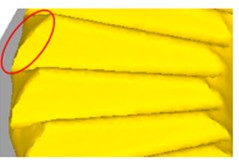
As shown in Fig. 16, larger inclination angles improve profile fullness. At 5°, about half the tooth top is unfilled (fullness 91.7 %). At 17.5°, filling is best (fullness 93.8 %). Therefore, an inclination angle of 17.5° is optimal for reducing force and improving fullness.
Fig. 16Tooth fullness under different inclination angles
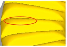
a) At 5°
b) At 10°

c) At15°

d) At 17.5°
5. Experimental verification
Experiments were conducted using optimized process parameters as shown in Table 2. Pre riveting is carried out on a riveting machine with 5° inclination angle, while tooth forming is carried out on a riveting machine with 17.5° inclination angle, as shown in Fig. 17. The forming process is divided into two stages: loading and smoothing. The loading path of the two-step rotary riveting (removed empty trips) is shown in Fig. 18.
Table 2Process parameters of face tooth forming
Parameters | 1st step forming | 2nd step forming |
Spindle speed | 600 rpm | 600 rpm |
Inclination angle | 5° | 17.5° |
Feed rate | 3.2 mm/s | 2 mm/s |
Fig. 17Face tooth rotary riveting apparatus
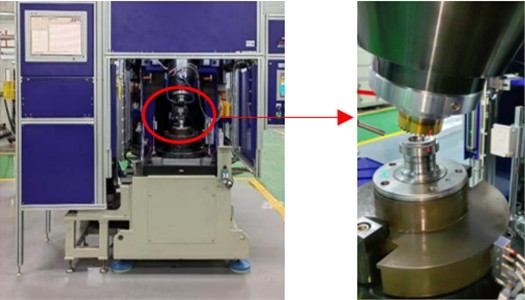
Fig. 18Loading path of two step rotary riveting
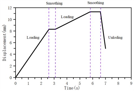
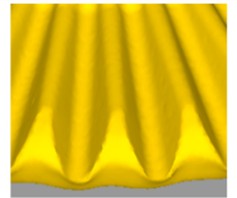
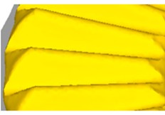
Fig. 19Sample after forming
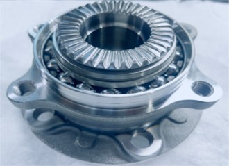
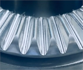
Formed samples are shown in Fig. 19. Tooth profile parameters were measured with a profilometer, the data are shown in Table 3. The optimized sample meets the design requirements, with high dimensional accuracy and good tooth profile quality. Forming force of the tooth forming recorded by the machine decreased from 276.8 kN (pre-optimization) to 264.1 kN (post-optimization), a 4.6 % reduction. Compared to the simulated forming force of 356.6 kN, the difference is 25.8 %. This difference comes from the accuracy of mold displacement, material model accuracy, and the influence of setting the inner ring as a rigid body (actually an elastic body). Tooth profile fullness increased from 91.6 % to 96.2 %, a 4.6 % improvement. Tooth profile fullness increased from 91.6 % to 96.2 %, a 4.6 % improvement.
Table 3Comparison of experimental result
Name | Design value | Before optimization | After optimization |
Outer diameter | 64 mm | 64.2 mm | 64.2 mm |
Tooth profile angle | 55° | 55.16 | 55.08° |
Root fillet radius | 0.7 mm | 0.72 mm | 0.68 mm |
Profile fullness | – | 91.6 | 96.2 % |
Forming force | – | 276.8 kN | 264.1 kN |
6. Conclusions
This study investigates the rotary riveting process for wheel hub bearing face teeth. Through finite element simulation and experimental verification, the influence of blank structure parameters, pre-riveting state, feed rate, spindle speed, and inclination angle on forming force and tooth profile fullness is analyzed, yielding optimal parameters. Main conclusions are:
(1) Among blank structural parameters, wall thickness most significantly affects profile fullness, followed by inner corner radius; outer fillet radius has the least effect.
(2) Pre-riveting state has a significant impact on tooth rotary riveting forming, a fully riveted state reduces axial forming force by 24.9 % and improves tooth profile fullness.
(3) Smaller feed rates and higher spindle speeds reduce forming force and improve profile fullness but may cause outer edge flash. Excessive feed rates and low speeds reduce fullness. A feed rate of 2 mm/s and spindle speed of 600 rpm are reasonable. Larger inclination angles reduce axial force and improve fullness; 17.5° is optimal.
(4) Experimental results confirm that optimized parameters increase tooth profile fullness by 4.6 % to 96.2 % and reduce forming force by 4.6 % compared to pre-optimization conditions.
This study focuses on the forming characteristics and the influence of process parameters for hub bearing face tooth. The proposed process parameter optimization scheme has been successfully applied in industrial production, significantly improving the assembly accuracy and fatigue life of wheel hub bearings, which verifies the engineering practicability of the technology. In the future, the microstructural evolution and the mold life improvement will be studied.
References
-
W. Xiong, Z.-D. Deng, J. Li, Y. Wang, H.-B. Zhang, and S. Mei, “Methods and characters for two-step cold rotary forging process of hub bearing face tooth,” Journal of Mechanical Science and Technology, Vol. 39, No. 10, pp. 6117–6125, Oct. 2025, https://doi.org/10.1007/s12206-025-0941-7
-
W. Zhuang, L. Hua, and X. Han, “Influences of key forging parameters on gear-tooth deviation of cold forged spur bevel gear,” Procedia Manufacturing, Vol. 15, pp. 504–510, Jan. 2018, https://doi.org/10.1016/j.promfg.2018.07.260
-
B. Gu, W. Zhuang, and X. Han, “Influences of key process parameters on orbital forging of thin-walled smartphone shell frame of aluminum alloy,” Procedia Manufacturing, Vol. 50, pp. 303–306, Jan. 2020, https://doi.org/10.1016/j.promfg.2020.08.056
-
X. Han, Y. Hu, and L. Hua, “A novel cold rotary forging method of producing multiple racks using one set of punch,” Journal of Manufacturing Science and Engineering, Vol. 140, No. 8, Aug. 2018, https://doi.org/10.1115/1.4039112
-
L. Zhu, C. Huang, X. Li, X. Chang, and Y. Li, “A two-step marginal-restraint mandrel-free spinning method for accuracy in forming large, special-shaped aluminum alloy tank domes,” Metals, Vol. 13, No. 7, p. 1205, Jul. 2023, https://doi.org/10.3390/met13071205
-
Q. Jin, X. Han, L. Hua, W. Zhuang, and W. Feng, “Process optimization method for cold orbital forging of component with deep and narrow groove,” Journal of Manufacturing Processes, Vol. 33, pp. 161–174, Jun. 2018, https://doi.org/10.1016/j.jmapro.2018.05.007
-
Z. Yu, M. Chen, C. Ma, S. Luo, and C. Zhu, “Numerical model simulation of the double-roll rotary forging of large diameter thin-walled disk,” Metals, Vol. 11, No. 11, p. 1767, Nov. 2021, https://doi.org/10.3390/met11111767
-
Z. Yu, C. Zhu, M. Chen, S. Luo, and C. Ma, “3D FE modeling simulation of the double-roll hot rotary forging of large diameter thin-walled metal disk,” The International Journal of Advanced Manufacturing Technology, Vol. 123, No. 5-6, pp. 2123–2137, Oct. 2022, https://doi.org/10.1007/s00170-022-10278-0
-
J. Wang et al., “Deformation characteristic and microstructure evolution of GH4169 alloy induced by axial upsetting and axial rotary forging,” Materials Characterization, Vol. 191, p. 112136, Sep. 2022, https://doi.org/10.1016/j.matchar.2022.112136
-
I. M. Russo, C. J. Cleaver, J. M. Allwood, and E. G. Loukaides, “The influence of part asymmetry on the achievable forming height in multi-pass spinning,” Journal of Materials Processing Technology, Vol. 275, p. 116350, 2020, https://doi.org/10.1016/j.jmatprotec.2019.116350
-
A. Bouragba, M. H. Miloud, I. Zidane, and M. Mendas, “Inverse identification of a coupled hardening law with GTN damage model parameters for cold-rolled steel: application to the deep drawing process,” International Journal of Material Forming, Vol. 18, No. 1, pp. 1–14, Dec. 2024, https://doi.org/10.1007/s12289-024-01866-4
-
W. Xiong, Y. Wang, X.-P. Li, S. Mei, and Z.-X. Tian, “Study on the forming process and deformation behavior of inner ring in the wheel hub bearing based on riveting assembly,” Materials, Vol. 12, No. 22, p. 3785, Nov. 2019, https://doi.org/10.3390/ma12223785
-
Y. Wang, W. Xiong, J.-H. Zhou, and P. Ren, “Numerical and experimental investigations on riveting assembly processing parameters of hub bearing unit,” in The Minerals, Metals and Materials Series, Cham: Springer International Publishing, 2021, pp. 1507–1515, https://doi.org/10.1007/978-3-030-75381-8_125
-
W. Li, Q. Chen, Y. Yang, Y. Xiao, and M. Li, “Investigation on clinching assembly process of automobile wheel hub bearings,” Proceedings of the Institution of Mechanical Engineers, Part D: Journal of Automobile Engineering, Vol. 235, No. 8, pp. 2114–2123, 2021, https://doi.org/10.1177/0954407020987912
-
S. H. Chung, J. D. Yoo, H. K. Moon, W. J. Chung, and M. S. Joun, “Implicit elastoplastic finite element analysis of a wheel bearing shaft clinching process using the multi-body function,” Metals, Vol. 12, No. 11, p. 1930, Nov. 2022, https://doi.org/10.3390/met12111930
About this article

This work was supported by the Hubei Provincial Natural Science Foundation of China (Grant numbers 2024AFD031), Key Project of Hubei Provincial Department of Education (D20232603). Author Wei Xiong received research support from Hubei Shuanglin bearing Co., Ltd.
The datasets generated during and/or analyzed during the current study are available from the corresponding author on reasonable request.
Xiong Wei established FE model of two step rotary riveting of hub bearing face tooth, Guo Yong-Kun investigated the influence of process parameters on tooth rotary riveting forming, Deng Zhong-Di investigated the influence of blank dimensions and pre-riveting state, Zhang Hai-Bo designed experimental verification and LV Shuo investigated the influence of mold inclination angle.
The authors declare that they have no conflict of interest.
