Abstract
In an era of increasing digital connectivity and device autonomy, the Internet of Things (IoT) represents a fundamental pillar of modern digital transformation. As the number of sensors and devices operating in environments without a stable power supply continues to grow, the demand for sustainable and autonomous energy solutions becomes critical. Efficient conversion of vibrational energy into electrical energy requires a carefully optimized mechanical design to ensure effective energy transfer to the transducers, particularly under low-frequency and small-amplitude conditions typical of real-world IoT applications. This study presents a comprehensive multiphysics investigation and energy-dynamic characterization of an elastic cantilever system integrating piezoelectric and electromagnetic transducers for vibration energy harvesting. Analytical and numerical models are developed to describe the coupled mechanical-electrical behavior of both harvesting mechanisms, supported by detailed finite element simulations performed in COMSOL Multiphysics. The dynamic response of the cantilever is analyzed for multiple mass configurations. The results demonstrate that modifying the mass distribution significantly shifts the natural frequencies and redistributes kinetic and potential energy across vibration modes, enabling optimized placement of energy transducers. The findings confirm the potential of hybrid cantilever-based harvesters to provide efficient, multifunctional, and sustainable energy solutions for self-powered IoT and smart monitoring systems.
1. Introduction
The increasing deployment of wireless sensor networks in modern technological systems, particularly within the framework of the Internet of Things (IoT), requires reliable and long-lasting sources of electrical energy [1]. Conventional battery-based solutions exhibit significant limitations, including limited lifespan, the need for periodic replacement or recharging, and the generation of environmentally harmful waste [2]. In this context, harvesting energy from mechanical vibrations has emerged as a sustainable and efficient alternative for powering low-power devices [3]. Vibrations represent one of the most abundant yet underutilized sources of ambient energy, commonly present in industrial environments, rotating machinery, transportation systems, and civil structures [4]. Their utilization provides a promising approach to addressing energy supply challenges, particularly in autonomous sensor systems and smart monitoring applications. Addressing these challenges requires a multidisciplinary engineering approach, encompassing the investigation of piezoelectric and electromagnetic transducers as well as the development of hybrid systems with enhanced energy conversion efficiency [5]. One of the key challenges in vibration energy harvesting lies in the design of mechanical structures capable of efficiently responding to excitations across a wide frequency range [6]. Most conventional systems operate near resonance and are therefore optimized for a narrow frequency bandwidth, typically relying on either piezoelectric or electromagnetic transduction principles [7-10]. A major engineering challenge is to design mechanical structures that not only respond over a broad frequency spectrum but also enable optimal integration with transducers to maximize energy conversion efficiency. Particular attention must be given to identifying regions within the mechanical structure characterized by maximum strain, stress, or vibration velocity, as these locations represent zones of highest energy potential for effective transducer placement [11].
Piezoelectric transducers represent one of the most widely used technologies for vibration energy harvesting [12-15]. However, their performance and power output strongly depend on several factors, including the properties of the piezoelectric material, the geometry and thickness of the active element, the mounting conditions, the electrical load, and the location of the transducer on the mechanical structure [16, 17]. Particular attention must be given to the coupling between the structural mode shapes and the operating mode of the piezoelectric element, as the appropriate selection of transducer location and orientation can significantly influence the harvested energy [18]. In addition, electrical impedance matching plays a critical role in determining the overall energy conversion efficiency, particularly under varying excitation frequencies [19, 20]. Piezoelectric materials are widely used for coupling the mechanical and electrical domains due to their bidirectional electromechanical conversion capability, enabling their use as both sensors and actuators. Owing to their high efficiency, capability for high-frequency operation, and corrosion resistance, they are applied across both micro-scale [21-24] and macro-scale systems [25, 26]. Cantilever-based configurations are among the most employed structures for vibration energy harvesting, typically operating near their natural frequencies and incorporating one or more piezoelectric transducers to maximize power output [27, 28]. This approach is favored due to its relatively simple mechanical design, high sensitivity, and ability to generate significant electrical power even under low vibration levels. The effectiveness of cantilever structures is largely attributed to their low resonant frequencies, which enable the generation of high strain levels even at small excitation amplitudes [29].
Electromagnetic transducers for vibration energy harvesting [30] are characterized by simple and economical construction, high robustness and low load impedance, which makes them suitable for direct utilization of kinetic energy from vibrations of mechanical structures [31]. However, the additional mass of the magnet and the coil affect the mass distribution and dynamic response of the entire structure, which can lead to a shift of the natural frequencies and a change in dynamic behavior. In addition, the changing magnetic field can induce eddy currents in the metal parts of the mechanical structure, which cause local heating and the creation of Lorentz force that damps the oscillations, leading to losses and reduced efficiency [32-34].
The integration of piezoelectric and electromagnetic transduction mechanisms within a hybrid energy harvesting system represents a significant research challenge, primarily due to the need to reconcile their distinct physical principles and electrical characteristics [35-38]. In addition, such systems require the development of dedicated power management electronics to enable efficient signal conditioning, energy storage, and continuous power delivery to the load.
Despite these challenges, hybrid approaches have attracted increasing research interest due to their potential to extend the operational frequency bandwidth and enhance overall energy conversion efficiency [39-42]. Numerous studies have investigated different aspects of vibration energy harvesting systems. For instance, piezoelectric bimorph cantilevers subjected to random vibrations have been analyzed both theoretically and experimentally [43], while energy harvesting from vortex-induced vibrations has been explored in [44, 45]. Furthermore, low-frequency energy harvesting concepts have also been demonstrated in MEMS-based systems operating under controlled excitation conditions [46].
The influence of structural parameters, particularly tip mass, on energy harvesting performance has been extensively studied [47-50], with results indicating that optimal power output is achieved when the added mass is approximately 25 % of the total cantilever mass. In addition, microfabricated piezoelectric harvesters [51], impact-based energy harvesting in composite piezoelectric beams [52], and comprehensive analyses of systems operating under random vibrations [53] have further contributed to the advancement of the field.
However, despite the extensive body of research, there remains a need for systematic investigation of hybrid systems that explicitly consider the interaction between mechanical modal behavior, spatial energy distribution, and the optimal placement of multiple transduction mechanisms within a single structure.
In this context, the present study proposes a hybrid energy harvesting system based on a cantilever structure with integrated piezoelectric and electromagnetic transducers. The system is designed through the identification of distinct energy zones corresponding to different modal characteristics. The key novelty of this work lies in the deliberate spatial separation of energy zones, enabling simultaneous and mode-specific optimization of piezoelectric and electromagnetic energy harvesting within a single hybrid structure.
2. Motivation
The increasing deployment of autonomous sensing systems within the Internet of Things (IoT) has created a strong demand for sustainable and maintenance-free energy solutions. Conventional battery-powered systems suffer from limited lifetime, frequent replacement requirements, and environmental concerns, particularly in industrial environments where access is restricted and maintenance costs are high. Among various ambient energy sources, mechanical vibrations represent a widely available and reliable source of energy, especially in industrial settings such as rotating machinery, transportation systems, and structural installations. However, one of the primary challenges in vibration energy harvesting is the inherently narrow operational bandwidth of conventional resonant harvesters, which significantly limits their performance under real-world conditions characterized by variable and broadband excitation. Piezoelectric energy harvesters are well known for their high voltage output and high efficiency, particularly in low-frequency regimes and in regions of high mechanical strain. In contrast, electromagnetic harvesters are more effective in regions characterized by high velocity and displacement, typically associated with higher vibration modes. Despite their respective advantages, both approaches exhibit inherent limitations when employed independently, particularly in terms of bandwidth and adaptability to varying excitation conditions. To address these limitations, hybrid energy harvesting systems that combine multiple transduction mechanisms have emerged as a promising solution. Integrating piezoelectric and electromagnetic transducers within a single structure enables the simultaneous exploitation of different physical domains and modal characteristics of the system. Furthermore, the use of multiple proof masses and coupled cantilever configurations allows for tuning multiple natural frequencies, thereby extending the operational bandwidth. Motivated by these challenges, this work investigates a hybrid multiphysics energy harvesting system based on a cantilever structure with strategically distributed energy conversion zones. The system is designed to exploit both the first and second vibration modes, enabling efficient energy extraction from strain-dominated and velocity-dominated regions. The proposed approach aims to enhance power output, broaden the operational bandwidth, and improve the applicability of energy harvesting systems under realistic industrial vibration conditions.
3. Energy analysis of cantilever beam
3.1. Dynamic analysis of cantilever beam
In this section, the cantilever beam is considered as an elastic system suitable for vibration energy harvesting applications. The cantilever configuration is selected as the fundamental model due to its structural simplicity and widespread implementation in practical engineering systems. Furthermore, it allows for the development of a mathematically tractable model while retaining sufficient fidelity for the analysis of real-world dynamic behavior. Within the numerical framework, three configurations are investigated: a cantilever without an added mass, a cantilever with a single added mass, and a cantilever with two added masses. These configurations enable a systematic analysis of the influence of mass distribution on the dynamic response of the system, as well as the identification of regions with high energy potent. Attention is given to the modal characteristics of the structure. The identification of nodal points of the mode shapes is of critical importance, as these locations exhibit zero transverse displacement and are therefore unsuitable for the placement of energy transducers. Instead, transducers should be positioned in regions of maximum strain or maximum vibration velocity, depending on the transduction mechanism (piezoelectric or electromagnetic). The proposed modeling approach enables not only an accurate evaluation of the energy distribution across vibration modes, but also the optimization of transducer placement within the structure. In this context, the cantilever beam serves as an effective medium for the accumulation, transfer, and conversion of mechanical vibration energy into electrical energy. To illustrate the energy distribution, Table 1 summarizes the characteristic parameters of the first two dominant vibration modes of the cantilever.
Table 1Characteristic parameters for the first two bending mode
Mode shape | Nodal points (/) | Maximum zone | Dominant energy | Suitable converter |
1 | (no node) | Area of clamping | Potential (bending) | Piezoelectric |
2 | 0.7835 | Central zone and peak | Kinetic (velocities) | Electromagnetic |
In the first vibration mode, the maximum strain and stress are concentrated near the clamped end of the cantilever, making this region suitable for the placement of piezoelectric transducers. In the second mode, a nodal point is located at approximately 0.7835 , while the highest vibration velocities occur in the region between the clamped end and the nodal point, which is favourable for the placement of electromagnetic transducers.
In this study, the finite element method (FEM) is implemented using the COMSOL Multiphysics software package to perform modal and energy analyses of the cantilever beam. The objective is to determine the natural frequencies, mode shapes, and spatial distribution of energy density. A cantilever beam without added masses or integrated transducers is considered as a reference configuration, serving as a baseline for comparison with subsequent cases involving added masses. These configurations enable the identification of regions with the highest energy potential and support the optimization of transducer placement. The specific objectives of the numerical analysis include: (i) determination of the first two natural frequencies and corresponding mode shapes, (ii) computation and visualization of the kinetic and potential energy distribution, and (iii) identification of regions with the highest potential for energy transducer placement.
The mechanical structure is modeled as a rectangular cantilever beam with length , width , and thickness , composed of a homogeneous and isotropic material characterized by Young’s modulus , Poisson’s ratio , and density . The boundary conditions correspond to a classical cantilever configuration: the beam is clamped at the left end (), while the free end () is free of reaction forces and bending moments.
An eigenfrequency analysis is performed in COMSOL Multiphysics to determine the natural frequencies and corresponding mode shapes. The obtained numerical results are compared with analytical solutions based on Euler-Bernoulli beam theory, where the natural angular frequencies and the corresponding natural frequencies are defined as follows:
where the first 3 solutions are 1.8751, 4.6941, 7.8548.
The comparison between the numerical results obtained from COMSOL Multiphysics and the analytical solutions enables validation of the accuracy and consistency of the simulations. In the initial stage, a cantilever beam without added masses or integrated transducers is considered as a reference configuration, serving as a baseline for comparison with subsequent scenarios. The objectives of this analysis include: (i) determination of the natural frequencies and corresponding mode shapes, (ii) evaluation of the kinetic and strain energy distribution, and (iii) identification of regions with the highest energy potential. The cantilever beam has a length 0.199 m, width 0.03 m, and thickness 0.001 m. The material is structural steel, characterized by Young’s modulus 210 GPa, density 7850 kg/m3, and Poisson’s ratio 0.3. The total mass of the cantilever is approximately 0.058 kg. In the finite element model, the cantilever is discretized using 11,988 triangular elements, resulting in a total of 72,003 degrees of freedom. An eigenfrequency analysis is performed without external excitation, as the solver determines the natural frequencies and corresponding mode shapes of the structure.
The first three eigenfrequencies and corresponding mode shapes are obtained. The first two natural frequencies are 20.68 Hz (Fig. 1(a)) and 129.53 Hz (Fig. 1(b)), showing excellent agreement with the analytical Euler-Bernoulli solution (deviation < 1 %). A third mode is identified at 270.19 Hz (Fig. 1(c)), corresponding to out-of-plane bending or torsional behavior, which does not belong to the classical in-plane bending mode sequence predicted by Euler-Bernoulli beam theory. This behavior is expected in three-dimensional models with finite cross-section dimensions, where additional deformation modes may occur. The next in-plane bending mode is observed at 363.12 Hz (Fig. 1(d)), with a deviation of approximately 2 % compared to the analytical solution.
The strong agreement between the numerical simulation results and the analytical calculations confirms the validity of the developed model and its suitability for further analyses. Within COMSOL Multiphysics, simulations of the spatial distribution of potential (strain) energy, kinetic energy, and dissipated power were performed. For the frequency response analysis, the system was subjected to harmonic excitation over a frequency range from 1 Hz to 140 Hz, ensuring that both the first and second bending modes were included. The excitation was applied as a harmonic force with a constant amplitude of 100 mN.
Fig. 1Comparison between numerical results with COMSOL and analytical calculations according to the Euler-Bernoulli theory
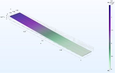
a) First bending mode = 20.68 Hz
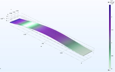
b) Second bending mode = 129.53 Hz
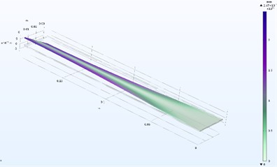
c) Third bending mode = 270.19 Hz
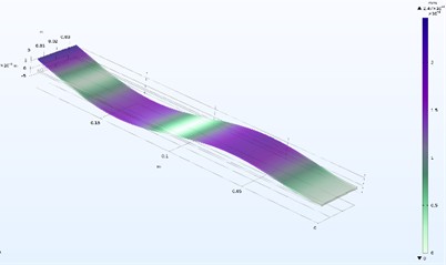
d) Fourth bending mode = 363.12 Hz
3.2. Dynamic analysis of cantilever beam with 1 added mass
Numerical simulations performed using the finite element method in COMSOL Multiphysics enable a detailed investigation of the influence of an added concentrated mass on the dynamic behavior of the cantilever beam. A tip mass ranging from 0 to 0.1 kg (0, 0.025, 0.05, 0.075, and 0.1 kg) is applied at the free end of the beam. For each configuration, the distributions of kinetic energy, strain (potential) energy, and dissipated power are evaluated, together with the identification of regions characterized by maximum vibration velocity and normal stress. The results, referenced against the baseline case without added mass, enable the identification of regions with high energy potential for the placement of piezoelectric and electromagnetic transducers. This analysis provides a foundation for optimizing the mass configuration to improve the efficiency of energy harvesting, as summarized in Table 2.
The results indicate that the total mechanical energy of the cantilever in the first bending mode remains relatively stable with increasing , while the natural frequency decreases significantly. Specifically, the first natural frequency is reduced from 19.1 Hz (without added mass) to 7.2 Hz for 0.1 kg, corresponding to a reduction of approximately 62 %. For the second bending mode, the natural frequency decreases from 124.9 Hz to 100.9 Hz for 0.1 kg, corresponding to a reduction of approximately 20 %. A variation in the ratio between kinetic and strain energy is also observed with increasing mass. Both energy components increase with , indicating enhanced energy storage within the system. The total strain energy increases from 0.41 mJ (without added mass) to 1.35 mJ for 0.1 kg, while the kinetic energy increases from 0.21 mJ to 0.68 mJ for the same configuration.
Table 2Influence of the added mass m1 on the natural frequencies of the cantilever
Added mass (kg) at the end of the cantilever beam | ||||||
Mass | 0 | 0.025 | 0.05 | 0.075 | 0.1 | Percentage change [%] |
[Hz] | 19.1 | 12.1 | 9.6 | 8.17 | 7.2 | 62 % |
[Hz] | 124.93 | 110 | 105.5 | 103.3 | 100.9 | 20 % |
The simulation results indicate that dissipative losses strongly depend on the added mass of the system. These losses represent the portion of mechanical energy dissipated as heat, leading to a gradual reduction of the system’s total energy and increased damping of the oscillations. In the first bending mode, the highest dissipative losses are observed in the configuration without added mass. As the mass increases, the dissipative losses gradually decrease, accompanied by a reduction in the natural frequency . Specifically, the losses decrease from 47 mW for the cantilever without added mass ( 19.2 Hz) to 17 mW for 0.1 kg ( 7.2 Hz), corresponding to a reduction of approximately 37 %. In contrast, in the second bending mode, the dissipative losses exhibit the opposite trend. The lowest losses are observed in the case without added mass, while increasing leads to higher dissipative losses, as summarized in Table 3. The losses increased from 3.2 mW (without added mass) to 8.5 mW for 0.1 kg a natural frequency of 100.9 Hz, corresponding to an increase of approximately 39 %.
This contrasting behavior between the first and second modes highlights the influence of mass distribution on energy dissipation mechanisms and provides important insight for optimizing energy harvesting performance.
Table 3Influence of the added mass m1 on the cantilever losses at the first mode
Added mass (kg) at the end of the cantilever beam | ||||||
Mass | 0 | 0.025 | 0.05 | 0.075 | 0.1 | Percentage change [%] |
[Hz] | 19.1 | 12.1 | 9.6 | 8.17 | 7.2 | 62 % |
Dissipation losses [mW] | 45 | 28 | 23 | 19 | 17 | 37 % |
Table 4Influence of added mass m1 on the cantilever losses at second mode
Added mass (kg) at the end of the cantilever beam | ||||||
Mass | 0 | 0.025 | 0.05 | 0.075 | 0.1 | Percentage change [%] |
[Hz] | 124.93 | 110 | 105.5 | 103.3 | 100.9 | 20 % |
Dissipation losses [mW] | 3.4 | 7.1 | 8.1 | 8.5 | 8.6 | 39 % |
Modal analysis reveals significant changes in both the bending mode shapes (Fig. 2) and the spatial distribution of kinetic and strain energy along the cantilever. In the first bending mode, the maximum kinetic energy remains concentrated near the free end of the cantilever, while the maximum strain (potential) energy is localized near the clamped end.
In the second mode, the presence of the added mass alters the position of the nodal point, which shifts away from the free end as the mass increases. This shift leads to a modification of the mode shape and a redistribution of energy along the beam. These results demonstrate that added masses influence not only the resonant frequencies of the cantilever, but also the spatial distribution of energy and stress. This behavior is critical for determining the optimal locations for integrating piezoelectric and electromagnetic transducers, with the aim of maximizing energy harvesting efficiency.
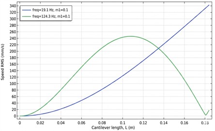
The simulation results further indicate that the velocity distribution along the cantilever varies significantly depending on the vibration mode and the presence of the added mass .
Fig. 2Modal shapes (first and second mode) of oscillations for different added masses m1
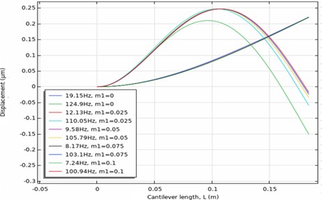
Fig. 3Zones of maximum normal stresses for the first mode f1= 7.2 Hz, and the second mode f2 = 124.9 Hz with an added mass m1 at the end of the cantilever
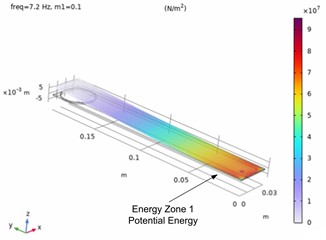
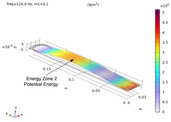
In the first bending mode, in the absence of added mass, the velocity increases progressively from the clamped end toward the free end, where it reaches its maximum value due to the largest vibration amplitude in this region. A characteristic feature of the second vibration mode is the presence of two regions with high vibration velocity, separated by a nodal point where the velocity approaches zero. The first region is located between the clamped end and the nodal point, while the second is situated near the free end of the cantilever. The addition of a mass alters the position of the nodal point and leads to a redistribution of the velocity profile along the structure. As the added mass increases, the velocity at the free end decreases, while the velocity in the region between the clamped end and the nodal point increases, as illustrated in Fig. 4.
Fig. 4Velocity distribution along the length of the cantilever with added mass m1= 0.1 kg
3.3. Dynamic analysis of cantilever beam with 2 added masses
The results of the previous analysis indicate that, in the second vibration mode, the region of maximum velocity is located between the clamped end and the nodal point. In addition, the motion in this region is predominantly rectilinear, which makes it particularly suitable for the integration of an electromagnetic transducer. The combination of high vibration velocity and near-linear displacement provides favorable conditions for the placement of the moving magnetic element, which constitutes the active component of the electromagnetic transducer. Based on these observations, an additional analysis of the dynamic behavior of the cantilever is performed by introducing a second added mass , positioned within this region, hereafter referred to as energy zone 2. The objective is to evaluate its influence on the modal characteristics, energy distribution, and the potential for improving energy conversion efficiency.
The simulations are performed with the first added mass fixed at 0.1 kg, while the second mass is varied over the range 0-0.1 kg (0, 0.025, 0.05, 0.075, and 0.1 kg). These configurations enable a systematic analysis of the influence of on the natural frequencies, mode shapes, distributions of kinetic and strain energy, as well as energy losses, with the objective of identifying optimal locations for energy transducer placement and maximizing energy harvesting efficiency. The results show that increasing the second mass , positioned in energy zone 2, has a significantly stronger influence on the second bending mode than on the first. The first natural frequency exhibits only a minor variation of approximately 3.5 %, decreasing from 7.72 Hz to 7.52 Hz for 0.1 kg. In contrast, the second natural frequency decreases substantially by approximately 49 %, from 103.16 Hz to 52.4 Hz. This pronounced reduction is attributed to the placement of within a region of high vibration velocity and significant modal participation, which effectively increases the inertia associated with the second mode.
Table 5Changes in natural frequency with the addition of a second mass m2
Added mass (kg)-energy zone 2, 0.1 kg. | ||||||
(kg) | 0 | 0.025 | 0.05 | 0.075 | 0.1 | Percentage change [%] |
[Hz] | 7.72 | 7.68 | 7. 62 | 7. 58 | 7. 52 | 3.5 % |
[Hz] | 103.16 | 77.8 | 65.38 | 57.7 | 52.4 | 49 % |
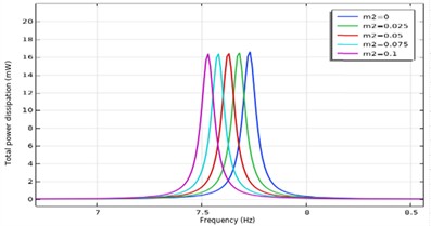
The analysis of energy parameters for the first bending mode (Fig. 5) indicates that the addition of the second mass has a relatively minor influence on both the magnitude and spatial distribution of the accumulated energy in the system. The maximum strain (potential) energy in the absence of added mass is approximately 36 mJ, decreasing gradually to about 31 mJ as increases. A similar trend is observed for kinetic energy, which decreases from an initial value of approximately 18 mJ to about 15 mJ at the highest added mass. The dissipated power also exhibits a decreasing trend, from approximately 17 mW without added mass to about 14 mW for the largest value of . This behavior indicates reduced dynamic activity and lower energy dissipation intensity as the system inertia increases. However, despite these variations, the relative relationship between the total stored energy and dissipated power remains nearly unchanged.
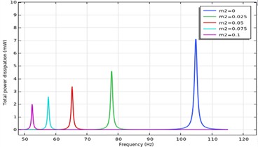
Fig. 5Dependence of the dissipative power on the variable mass m2
a)0.1 kg
b)0.1 kg
The analysis of the second bending mode (Fig. 6) shows that the addition of the second mass has a significantly stronger influence on the energy parameters of the system compared to the first mode. The maximum strain (potential) energy without added mass is approximately 1.05 mJ, decreasing to below 0.5 mJ as increases. A similar trend is observed for the kinetic energy, which decreases from an initial value of approximately 0.55 mJ to about 0.2 mJ at the highest added mass. These results indicate that increasing the system inertia leads to a reduction in the total stored mechanical energy in the second mode. The dissipated power follows a comparable trend, decreasing from approximately 7.5 mW (without added mass) to less than 3 mW for 0.1 kg. This reduction in dissipative losses suggests a lower rate of damping and a longer retention of mechanical energy within the system. Overall, these results demonstrate that the introduction of significantly alters the energy characteristics of the second mode, providing a mechanism for controlling both energy distribution and dissipation behavior.
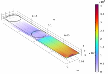
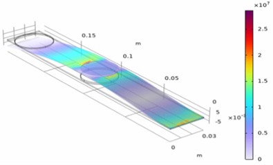
Fig. 6Zones of maximum normal stresses for the first mode f1= 7.2 Hz, and f2 = 52.4 Hz for the second mode with a second added mass m2= 0.1 kg
a)
b)
The velocity distribution along the cantilever for the first and second vibration modes (Fig. 7) clearly illustrates the differences in the dynamic behavior of the system. In the first bending mode (blue curve), the velocity increases progressively from the clamped end toward the free end, where it reaches its maximum value. This behavior is consistent with the largest displacement amplitude occurring in this region and indicates that the kinetic energy is predominantly concentrated near the free end of the cantilever.
Fig. 7Distribution of effective velocity along the length of the cantilever for m2= 0.1 kg location second energy zone
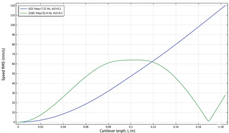
In contrast, the velocity distribution for the second bending mode (green curve) exhibits a significantly different profile. Two distinct regions of high velocity are observed, separated by a nodal point where the velocity approaches zero. The first high-velocity region is located near the free end of the cantilever, while the second is positioned at approximately 0.08-0.12 m from the clamped end.
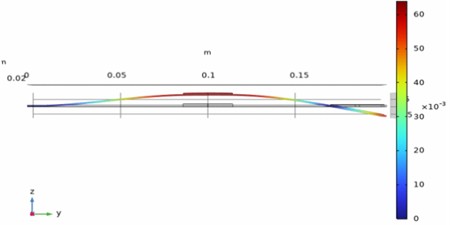
The placement of the second mass (Fig. 8), which represents the permanent magnet in the practical implementation, is selected to enable predominantly rectilinear motion along the -axis. Such a configuration offers several advantages. First, rectilinear motion ensures stable and controlled relative displacement between the magnet and the coil, minimizing the risk of mechanical contact, collision, or structural damage. Second, the introduction of the second mass leads to the formation of localized normal stresses in the region behind the magnet position. This creates additional potential for exploiting strain energy in this zone. As a result, the proposed configuration enables hybrid energy conversion from multiple regions of the structure, thereby Analytical and Multiphysics modelling of piezoelectric energy harvester.
Fig. 8Axial movement of the magnet during the second oscillation mode
3.4. Analytical modelling of piezoelectric energy harvester
Piezoelectric transducers represent one of the most widely used technologies for converting mechanical vibration energy into electrical energy. Their operation is based on the direct piezoelectric effect, whereby mechanical deformation of a crystalline or ceramic material generates an electric charge and a corresponding potential difference across the electrodes. This effect is reversible, enabling the same materials to function as actuators, where an applied electric field induces controlled mechanical deformation.
Among the available materials, piezoelectric ceramics based on PZT (lead zirconate titanate) are most commonly used in energy harvesting applications due to their high piezoelectric coefficients and stability. In addition, polymer-based materials such as PVDF (polyvinylidene fluoride) are employed in applications requiring greater flexibility and operation under low-strain conditions. When an elastic structure, such as a cantilever beam, undergoes vibration, the highest electric charge is generated in regions with maximum mechanical strain. Consequently, piezoelectric elements are typically integrated near the clamped end of the cantilever, where deformation is greatest. At higher vibration modes, additional strain-dominated regions may be exploited, enabling improved utilization of the available mechanical energy.
The main advantages of piezoelectric transducers include high energy density, ease of integration into structural components, high sensitivity to local deformation, compactness, and robustness. However, their limitations include relatively high output impedance, the requirement for impedance matching circuits, and sensitivity to temperature variations. In the context of this research, piezoelectric transducers are employed as the primary mechanism for harvesting energy from strain-dominated regions of the cantilever, with the objective of maximizing energy conversion efficiency. The electromechanical behavior of piezoelectric materials is described by constitutive equations that couple mechanical and electrical fields. In linear form, these relations can be expressed as:
where is the strain vector, is the stress vector, is the electric field vector, and is the electric displacement vector. The matrix denotes the elastic compliance at constant electric field, is the piezoelectric strain coefficient matrix, and represents the dielectric permittivity matrix at constant stress. These constitutive relations describe the electromechanical coupling in piezoelectric materials, whereby mechanical stresses generate an electric field and, conversely, an applied electric field induces mechanical deformation. For the cantilever-based energy harvester considered in this study, the dominant coupling mechanism corresponds to the transverse mode, which governs the interaction between bending-induced normal stresses and the generated electric field. Accordingly, for a one-dimensional bending configuration, such as a cantilever beam with an integrated piezoelectric layer, the constitutive relations can be simplified as follows:
The equivalent electrical model of the piezoelectric transducer can be represented using a Norton equivalent circuit, consisting of a current source in parallel with a capacitor and a resistor, as illustrated in Fig. 9.
Fig. 9Electrical equivalent model of the piezoelectric transducer
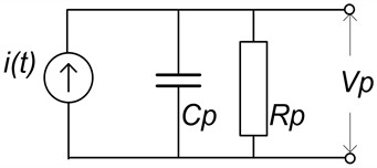
The parallel resistance represents the dielectric losses within the piezoelectric material. Its value for typical piezoelectric transducers ranges from 108 to 109 Ω. The resistance can be calculated as:
where – frequency, – capacitance.
The electric charge generated in the piezoelectric transducer is directly related to the applied mechanical stress and can be expressed as:
Based on the constitutive relations presented above, the open-circuit voltage of the piezoelectric transducer can be expressed as a function of the mechanical stress distribution . This relation quantifies the coupling between the applied mechanical stress, the piezoelectric coefficient , the dielectric permittivity , and the effective electrode area :
If the stresses are uniform, then one can write:
where is the active area of the piezo transducer and is the thickness of the piezo transducer.
The output current of the piezoelectric transducer corresponds to the time derivative of the total electric charge on the electrodes and can be expressed as:
The complete expression for the output current can be derived as follows:
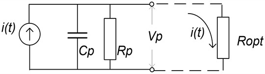
This equation describes the relationship between the applied mechanical stress, the generated source current, and the electrical dynamics of the piezoelectric transducer. Under closed-circuit conditions (Fig. 10), the current flowing through the circuit depends on the rate of change of the electric charge , which is directly related to the time variation of the mechanical stress . In the frequency domain, the current magnitude is governed by the electrical impedance of the circuit and can be expressed a:
For low frequencies the resistance can be neglected. The power in an electrical circuit can be calculated as:
Fig. 10Equivalent circuit diagram of a piezoelectric transducer in a closed circuit
3.5. Multiphysics analysis of piezoelectric energy harvester
A multiphysics simulation of a PI Ceramic P-876.A11 piezoelectric transducer integrated into a cantilever structure was conducted using COMSOL Multiphysics, in order to analyze the coupled electromechanical behavior and electrical performance of the system. The geometry and key characteristics of the transducer are presented in Fig. 11 and Table 6. The simulation model employs a predefined material library in COMSOL Multiphysics, incorporating the required mechanical, electrical, and piezoelectric properties. These parameters, defined according to the manufacturer’s technical specifications, serve as the basis for both the numerical simulations and the subsequent experimental validation.
Fig. 11Piezoelectric transducer P-876.A11 and dimensions

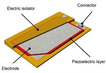
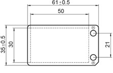
Table 6Basic characteristics of the piezoelectric transducer P-876.A11
Parameter | Quantity |
Active length (mm) | 50 |
Active width (mm) | 30 |
Piezo ceramic layer thickness (mm) | 0.1 |
Capacitance (nF) ± 20 % | 150 |
Piezo coefficient d33 (pC/N) | 320-400 |
Piezo material | PIC255 |
Minimum lateral contraction (µε) | 400 |
Relative lateral contraction ((µε)/V) | 1.6 |
3.6. Multiphysics analysis of piezoelectric energy harvester in zone 1 and zone 2
Multiple simulations were carried out with cantilever without added mass, with only 1 added mass (47 g and 94 g) and with 2 added masses (each 47 g and 94 g). The results are shown in Table 7.
Table 7Simulation results of a piezoelectric transducer with varied added masses in energy zone 1 and 2 (Power refers to RMS electrical power on optimal resistive load.)
Configuration | Natural frequency | (Hz) | (Vrms) | Power (mW) | Optimal resistance (kΩ) |
Zone 1 – no mass | First | 15.25 | 18 | 1.7 | 100 |
Second | 89.3 | 4 | 0.48 | 17.3 | |
Zone 1 – mass 47 g | First | 8.2 | 19.3 | 0.98 | 181 |
Second | 73.9 | 1.8 | 0.08 | 20 | |
Zone 1 – mass 94 g | First | 5.82 | 21 | 0.76 | 230 |
Second | 69.74 | 1.42 | 0.046 | 22 | |
Zone 1 – mass 94 g and 94 g | First | 6.5 | 16.23 | 0.56 | 232 |
Second | 43.9 | 1.9 | 0.055 | 35 | |
Zone 2 – mass 47 g | First | 8.18 | 1.75 | 0.0075 | 217 |
Second | 71 | 19 | 13.8 | 23 | |
Zone 2 – mass 94 g | First | 5.84 | 1.81 | 0.0054 | 310 |
Second | 66.89 | 18.5 | 9.6 | 19 | |
Zone 2 – mass 94 g and 94 g | First | 6.6 | 18 | 0.7 | 240 |
Second | 49 | 6.8 | 1.81 | 13 |
A multiphysics simulation analysis of a cantilever structure with an integrated piezoelectric transducer in energy zones 1 and 2 was conducted for three configurations: massless, single-mass ( 47 g, 47 g), and dual-mass ( 94 g, 94 g). The analysis enables a detailed investigation of the dynamic response and energy distribution of the system. In energy zone 1, the addition of mass results in a significant shift of the natural frequencies toward lower values. The first natural frequency decreases from 15.25 Hz (massless case) to 5.82 Hz ( 94 g), accompanied by an increase in output voltage from 18 Vrms to 21 Vrms. However, the output power exhibits a non-monotonic behavior, reaching a maximum of 2.1 mW at 47 g. In the dual-mass configuration, the first natural frequency slightly increases to 6.5 Hz, while both voltage and power decrease to 16.23 Vrms and 0.56 mW, respectively. In energy zone 2, the first mode is characterized by relatively low voltage (1.75-18 Vrms) and power levels (0.0054-0.7 mW). In contrast, the second mode achieves significantly higher outputs, particularly for 47 g (19 Vrms, 13.8 mW) and 94 g (18.5 Vrms, 9.6 mW). The addition of a second mass ( 94 g, 94 g) increases the power in the first mode (0.7 mW), but reduces it in the second mode (1.81 mW).
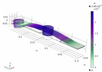
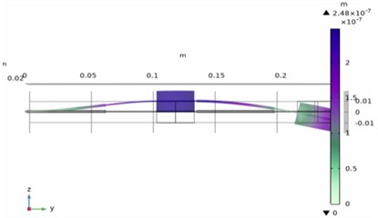
These results demonstrate that energy zone 2 is significantly more effective in the second vibration mode, whereas energy zone 1 provides superior performance in the first mode. Furthermore, the energy distribution can be tuned through appropriate mass configuration, enabling adaptation to specific target frequency ranges. An additional advantage arises from the approximately rectilinear motion of the mass (Fig. 12), which in practical implementation acts as the permanent magnet of an electromagnetic transducer in the second mode, thereby enabling enhanced hybrid energy harvesting performance.
Fig. 12Piezoelectric transducer placed on a cantilever with additional masses m1= 94 g and m2= 94 g for resonant frequency 51.1 Hz
4. Analytical and multiphysics modelling of electromagnetic energy harvester
4.1. Analytical modelling of electromagnetic energy harvester
Electromagnetic transducers, also referred to as electromagnetic vibration energy generators, represent a structurally simple and robust solution for converting mechanical energy into electrical energy. Their typical configuration consists of a permanent magnet and a conductive coil, enabling straightforward integration into a wide range of mechanical systems. These transducers are characterized by compact design, relatively low mass, and low output impedance, which allows efficient operation under higher electrical loads and improved utilization of available mechanical vibration energy. They are particularly suitable for regions with high vibration velocities, where significant relative motion between the magnet and the coil can be achieved.
The operating principle is based on Faraday’s law of electromagnetic induction, according to which a time-varying magnetic flux through a conductor induces an electromotive force (EMF). This principle enables effective energy conversion from dynamic mechanical motion into electrical output. Fig. 13 presents a schematic representation of an electromagnetic transducer, illustrating its fundamental components: a permanent magnet and a coil.
Fig. 13Schematic representation and basic structural elements of an electromagnetic transducer
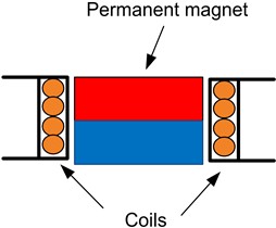
The induced voltage is the open circuit voltage generated when the coil is not connected to a load. When the coil is connected to a load with resistance , the voltage across the coil depends on the value of the resistance , the coil inductance , and the rate of change of current . In that case, the equation takes the form as:
where: is the voltage caused by self-induction of the coil, is the voltage across the circuit resistance, and is the current through the coil.
Eq. (14) describes the dynamics of an electromagnetic transducer when integrated into a closed circuit. The voltage induced in the winding is an alternating voltage with a frequency corresponding to the oscillations of the mechanical structure. For an alternating voltage model can be represented by an impedance , which includes resistive and inductive components:
where is the inductive reactance. This impedance defines the system’s response to alternating current and is crucial for efficient energy transfer. The integration of electromagnetic transducers into mechanical structures such as a cantilever beam focuses on positioning to maximize vibration absorption. The electromagnetic transducer is modeled with an ideal source of in series with the coil resistance and the coil inductance . For an alternating voltage with a circular frequency 𝜔, the total series impedance with the resistive load can be written as:
In a closed circuit (Fig. 14), according to Eq. (16) the current in the circuit will also depend on the load resistance .
Fig. 14The equivalent circuit of the electromagnetic transducer
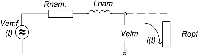
The magnitude of the electrical impedance of an electrical circuit is:
From here for the current ) depending on the frequency we can write:
The voltage across the resistor is:
We can calculate the power in an electrical circuit as:
Two approaches can be used to determine the optimal load resistance of an electromagnetic transducer. The first is an engineering-based approach grounded in classical AC circuit theory. In this case, the transducer is modeled as a voltage source with a series impedance composed of the coil resistance and the inductance . The optimal load resistance , which ensures maximum power transfer, is obtained when it is equal to the magnitude of the source impedance, i.e.:
This formulation is direct and practical, as it involves only measurable electrical parameters of the coil and the operating frequency, enabling straightforward experimental validation.
The second approach is based on an electromechanical analogy and enables a more comprehensive analysis of the system. In this case, the optimal electrical resistance is determined by matching the mechanical and electrical damping, which represents the condition for maximum energy conversion efficiency. By deriving the energy balance and coupling relationships of the transducer, the following expression is obtained:
where is the electromechanical constant of the converter, is the mechanical damping coefficient, is the quality factor of the system, represents the resistance of the winding.
This expression not only defines the optimal electrical resistance but also emphasizes the relationship between the mechanical and electrical parameters of the system. Thus, the approach opens the possibility of optimization through a combination of electrical and mechanical design.
4.2. Multiphysics analysis of electromagnetic energy harvester in zone 1
The definition of electromagnetic transducer parameters in COMSOL Multiphysics is essential for accurately modeling real operating conditions, as it encompasses geometric, material, and electrical characteristics of the system. The simulation considers key parameters such as the vibration frequency and amplitude, the distance between the magnet and the coil, magnetic flux density, number of coil turns, electrical load resistance , and wire geometry. Accurate specification of these parameters enables a realistic representation of the system and provides a reliable basis for estimating the induced voltage and output power.
Fig. 15Simulation of the magnetic field of an electromagnetic transducer
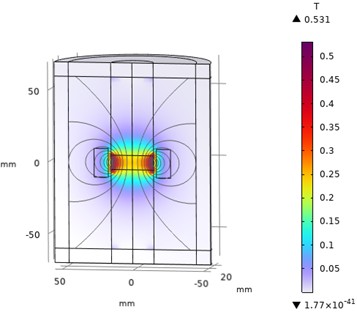
Fig. 15 illustrates the magnetic field distribution around a cylindrical NdFeB permanent magnet (grade N52) positioned at the center of the model. The AC/DC Magnetic Fields interface in COMSOL Multiphysics was used to compute and visualize the magnetic field distribution. The results show that the magnetic flux density is highest near the pole regions of the magnet, reaching values of approximately 0.8 T, and gradually decreases with increasing distance from the magnet.
This spatial distribution is of particular importance, as the induced voltage depends not only on the rate of change of magnetic flux through the coil, but also on the spatial alignment between the magnetic field and the coil position.
Fig. 16 presents the displacement distribution along the cantilever length at the first natural frequency (6.6 Hz) and the second natural frequency (49 Hz) for a configuration with additional masses 94 g and 94 g. The simulation results indicate that, at the location of the permanent magnet, the displacement amplitude reaches approximately 0.6 mm in both vibration modes. This finding implies that, in practical system design, a minimum clearance of at least 0.6 mm between the magnet and the coil is required to prevent mechanical contact or collision during operation. In the simulation model, the coil is defined with a height of 0.7 mm, ensuring sufficient mechanical clearance for safe oscillatory motion of the magnet within the operating range, while maintaining realistic conditions consistent with expected system performance.
Fig. 16Displacements along the length of the cantilever during vibrations with frequencies of 6.6 Hz and 49 Hz
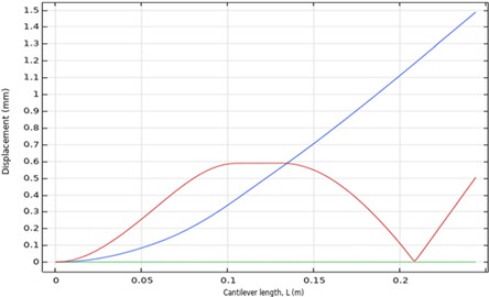
Fig. 17 presents the simulation results of the induced voltage, current, and output power of the electromagnetic transducer at the first natural frequency of the system (6.7 Hz). The results indicate that the induced voltage in the coil reaches approximately ±0.3 Vpp, while the current through the resistive load is about ±0.3 mApp. The corresponding electrical power delivered to the load is approximately 0.08 mW. These results confirm that, at low vibration frequencies, energy conversion efficiency is limited by the low rate of change of the magnetic flux.
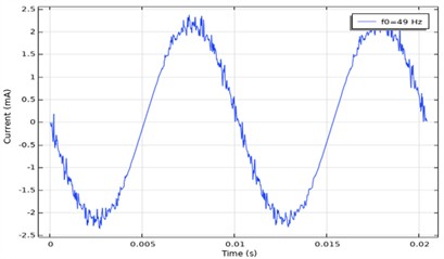
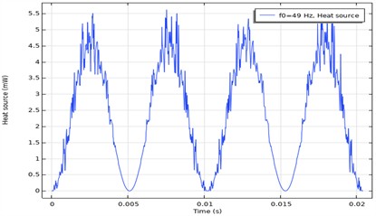
Fig. 18(a) presents the induced voltage in the coil at a natural frequency of 49 Hz, while Fig. 18(b) shows the corresponding current through the load for a resistive load of 1230 Ω. Fig. 18(c) illustrates the output electrical power, i.e., the power dissipated in the load resistor.
According to the simulation results, the induced voltage reaches approximately ±2.4 Vpp, while the current through the load is about ±2 mApp. The corresponding output power is in the range of 3-4 mW. These results demonstrate that, with increasing vibration frequency, the rate of change of magnetic flux through the coil increases, leading to a significant rise in the induced voltage and, consequently, higher output power.
Simulations of the electromagnetic transducer performed in COMSOL Multiphysics enabled both quantitative and qualitative analysis of the conversion of mechanical vibration energy into electrical energy. The results confirm that the induced voltage and output power depend on the vibration frequency and amplitude, as well as on the magnetic flux density and the relative position between the magnet and the coil. At the first natural frequency (6.7 Hz), the induced voltage in the coil reaches approximately ±0.3 V, with a corresponding output power of about 0.08 mW. These values are consistent with operation in a low-frequency regime, where the limited rate of change of magnetic flux restricts the energy conversion capability. In contrast, at the second natural frequency (49 Hz), the induced voltage increases to approximately ±2.4 V, while the output power reaches 3-4 mW. This significant increase is attributed to the higher relative velocity between the magnet and the coil, which enhances electromagnetic induction.
Fig. 17Parameters of the system for a natural frequency of 6.7 Hz
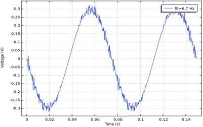
a) Induced Voltage in the coils
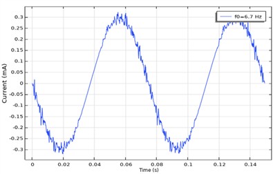
b) Generated current in the coils
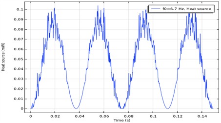
c) Generated power of the electromagnetic transduser
Fig. 18Parameters of the system for a natural frequency of 49 Hz
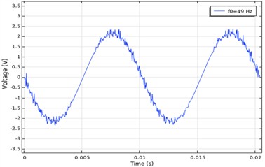
a) Induced voltage in the coils
b) Generated current in the coils
c) Generated power of the electromagnetic transducer
Magnetic field analysis further reveals that the highest magnetic flux density is concentrated near the pole regions of the magnet, emphasizing the importance of precise coil placement for maximizing electromagnetic coupling and output power. Overall, the results demonstrate that the electromagnetic transducer is capable of generating practically usable energy levels, particularly in the frequency range of 40-60 Hz, making it suitable for low-power and autonomous IoT applications.
5. Discussion of the results
5.1. Modal behaviour discussion
The developed numerical models in COMSOL Multiphysics enable accurate prediction of the dynamic behavior of the system, including mode shapes and the distribution of kinetic, potential, and dissipative energy across different excitation frequencies. The results indicate that the first and second natural frequencies represent the dominant energy-carrying modes of the system.
Parametric simulations with added masses demonstrate that modifying mass distribution enables controlled tuning of the natural frequencies and redistribution of energy between the fundamental vibration modes. The addition of a tip mass leads to a significant reduction in the first natural frequency, decreasing from 19.1 Hz (without added mass) to 7.2 Hz for 100 g, corresponding to a reduction of approximately 62 %. In comparison, the second natural frequency decreases from 124.9 Hz to 100.9 Hz (approximately 20 %), indicating that predominantly affects the first vibration mode. In contrast, the addition of a second mass in energy zone 2 has a much stronger influence on the second vibration mode. The first natural frequency changes only slightly, from 7.72 Hz (without ) to 7.52 Hz for 100 g (approximately 3.5 %). However, the second natural frequency decreases significantly from 103.16 Hz to 52.4 Hz, representing a reduction of approximately 49 %. These results confirm that selective mass placement enables targeted modal tuning, allowing independent control of the first and second vibration modes and their associated energy distributions.
5.2. Power output discussion
The addition of tip masses causes a change in the natural frequencies of the cantilever, but at the same time the modal analysis reveals significant changes in the oscillation shapes, as well as in the distribution of kinetic and potential energy along its length. In the first mode, the zone with the highest kinetic energy remains concentrated at the free end of the cantilever, while the maximum potential energy occurs near the clamped end. In the second mode, the added mass affects the position of the nodal point, when increasing the mass, it moves away from the end of the cantilever, which leads to a change in the modal shape and in the distribution of the effective velocity along the length of the structure. The analysis showed that the selected position of the mass , in addition to being characterized by the highest effective speeds, also allows for almost rectilinear motion along the -axis which has multiple advantages. Rectilinear motion is particularly suitable for the electromagnetic transducer, as it allows for stable and controlled relative displacement between the magnet and the coil, without the risk of mechanical contact, collision or damage. After the introduction of the second mass , localized normal stresses additionally appear in the zone behind the magnet position, which creates a new potential for utilizing potential energy in this area as well. Based on these results, energy zones for the integration of converters were defined, determining energy zone located near the clamped end, suitable for a piezoelectric transducer, an energy zone located at the position of the maximum amplitude peak at the second natural frequency, suitable for an electromagnetic transducer, and an energy zone immediately after the maximum amplitude at the second natural frequency, suitable for harnessing the potential energy through a second piezoelectric transducer. Using a multiphysics approach in COMSOL Multiphysics, detailed models have been developed that encompass the coupled mechanical, electrical, and magnetic domains, allowing for quantitative evaluation of energy conversion in various configurations. This analysis is not limited to individual converters but rather lays the foundation for their integration into a hybrid system, where the complementary advantages of both principles enable increased operating efficiency.
6. Conclusions
The development of analytical models for both piezoelectric and electromagnetic transducers established the fundamental mathematical relationships between the mechanical and electrical domains, enabling an analytical description of the energy conversion processes within the system.
The piezoelectric model captures the relationship between mechanical stresses in the cantilever and the generated electrical voltage through the material’s piezoelectric constants. In parallel, the electromagnetic model describes the relationship between the relative motion of the magnet and the coil and the induced voltage, based on Faraday’s law of electromagnetic induction. These models enable analytical estimation of voltage, current, and energy output as a function of the system dynamics.
Subsequently, numerical simulations of the cantilever structure with integrated transducers were performed for different configurations, including cases with and without added masses. The results confirm that optimal transducer performance strongly depends on their placement within the identified energy zones. Specifically, positioning the piezoelectric transducer near the clamped end (energy zone 1) yields the highest voltage and power in the first vibration mode, whereas placement in energy zone 2 is more effective for higher modes.
The introduction of additional masses significantly influences the modal characteristics and energy distribution. Increasing the tip mass reduces the first natural frequency and amplifies strain near the clamped end, leading to increased piezoelectric voltage, although with limited power output. In contrast, the introduction of a second mass in energy zone 2 primarily affects the second vibration mode, enhancing velocity levels and enabling higher energy extraction.
The configuration with two added masses ( 94 g, 94 g) represents an optimal compromise for the proposed hybrid architecture. It provides efficient piezoelectric energy harvesting in the first mode (energy zone 1) and stable performance in the second mode (energy zone 2). Moreover, this configuration enables nearly rectilinear motion of , which functions as the permanent magnet of the electromagnetic transducer along the -axis. This motion ensures stable spacing between the magnet and the coil, minimizes lateral deviations, and reduces magnetic flux losses.
Importantly, the resulting second natural frequency ( 49 Hz) lies within the typical industrial vibration range of 40-60 Hz, confirming the practical applicability of the proposed system. These findings demonstrate that the selected mass configuration provides an effective balance between modal tuning, energy distribution, and hybrid energy conversion performance.
While recent experimental investigations [54] have confirmed the practical performance of the system, the present work addresses the lack of a comprehensive analytical and numerical framework for describing the coupled electromechanical behavior of hybrid energy harvesters.
References
-
M. U. Mushtaq, H. Venter, A. Singh, and M. Owais, “Advances in energy harvesting for sustainable wireless sensor networks: challenges and opportunities,” Hardware, Vol. 3, No. 1, Feb. 2025, https://doi.org/10.3390/hardware3010001
-
M. Grossi, “Energy harvesting strategies for wireless sensor networks and mobile devices: a review,” Electronics, Vol. 10, No. 6, p. 661, Mar. 2021, https://doi.org/10.3390/electronics10060661
-
K. T. Prajwal, K. Manickavasagam, and R. Suresh, “A review on vibration energy harvesting technologies: analysis and technologies,” The European Physical Journal Special Topics, Vol. 231, No. 8, pp. 1359–1371, 2022, https://doi.org/10.1140/epjs/s11734-022-00490-0
-
L. T.-E. Nyamayoka and F. L. Inambao, “A review of vibration energy harvesting, techniques and applications,” Propulsion Tech Journal, Vol. 44, No. 5, pp. 1001–4055, 2023.
-
M. Wang et al., “A hybrid triboelectric-piezoelectric-electromagnetic generator with the high output performance for vibration energy harvesting of high-speed railway vehicles,” Nano Energy, Vol. 132, p. 110417, Dec. 2024, https://doi.org/10.1016/j.nanoen.2024.110417
-
S. Roundy, P. K. Wright, and J. M. Rabaey, Energy Scavenging for Wireless Sensor Networks. Boston, MA: Springer US, 2004, https://doi.org/10.1007/978-1-4615-0485-6
-
M. Iqbal et al., “Vibration-based piezoelectric, electromagnetic, and hybrid energy harvesters for microsystems applications: a contributed review,” International Journal of Energy Research, Vol. 45, No. 1, pp. 65–102, 2020, https://doi.org/10.1002/er.5643
-
R. Esmaeeli et al., “Design, modeling, and analysis of a high performance piezoelectric energy harvester for intelligent tires,” International Journal of Energy Research, Vol. 43, No. 10, pp. 5199–5212, 2019, https://doi.org/10.1002/er.4441
-
H. Weiwei, L. Zengwei, L. Zhuohao, Y. Xudong, and L. Xiaoning, “A low-frequency rotating electromagnetic vibration energy havester,” Sustainable Energy Technologies and Assessments, Vol. 82, p. 104492, Oct. 2025, https://doi.org/10.1016/j.seta.2025.104492
-
H. Liang, G. Hao, and O. Z. Olszewski, “A review on vibration-based piezoelectric energy harvesting from the aspect of compliant mechanisms,” Sensors and Actuators A: Physical, Vol. 331, p. 112743, Nov. 2021, https://doi.org/10.1016/j.sna.2021.112743
-
L. Wang et al., “Broadband vibration energy harvesting for wireless sensor node power supply in train container,” Review of Scientific Instruments, Vol. 90, No. 12, p. 125003, Dec. 2019, https://doi.org/10.1063/1.5127243
-
E. Brusa, A. Carrera, and C. Delprete, “A review of piezoelectric energy harvesting: materials, design, and readout circuits,” Actuators, Vol. 12, No. 12, p. 457, Dec. 2023, https://doi.org/10.3390/act12120457
-
M. Shirvanimoghaddam et al., “Towards a green and self-powered Internet of Things using piezoelectric energy harvesting,” IEEE Access, Vol. 7, pp. 94533–94556, 2019, https://doi.org/10.1109/access.2019.2928523
-
N. Sezer and M. Koç, “A comprehensive review on the state-of-the-art of piezoelectric energy harvesting,” Nano Energy, Vol. 80, p. 105567, Feb. 2021, https://doi.org/10.1016/j.nanoen.2020.105567
-
Z. Zhao, Y. Dai, S. X. Dou, and J. Liang, “Flexible nanogenerators for wearable electronic applications based on piezoelectric materials,” Materials Today Energy, Vol. 20, p. 100690, Jun. 2021, https://doi.org/10.1016/j.mtener.2021.100690
-
W. Sheng, H. Xiang, Z. Zhang, and J. Wang, “Experimental study and application of a self-powered wireless health monitoring system for railway bridges based on piezoelectric energy harvesting,” Energy, Vol. 317, p. 134583, Feb. 2025, https://doi.org/10.1016/j.energy.2025.134583
-
G. Jing, R. Zhang, D. P. Connolly, W. Hou, and P. Aela, “Piezoelectric energy harvesters for railways: recent trends and future opportunities,” Multiscale and Multidisciplinary Modeling, Experiments and Design, Vol. 8, No. 7, p. 325, May 2025, https://doi.org/10.1007/s41939-025-00919-8
-
G. K. Ottman, H. F. Hofmann, A. C. Bhatt, and G. A. Lesieutre, “Adaptive piezoelectric energy harvesting circuit for wireless remote power supply,” IEEE Transactions on Power Electronics, Vol. 17, No. 5, pp. 669–676, Sep. 2002, https://doi.org/10.1109/tpel.2002.802194
-
J. Liang and W.-H. Liao, “Impedance modeling and analysis for piezoelectric energy harvesting systems,” IEEE/ASME Transactions on Mechatronics, Vol. 17, No. 6, pp. 1145–1157, Dec. 2012, https://doi.org/10.1109/tmech.2011.2160275
-
A. Quattrocchi et al., “A new approach for impedance tracking of piezoelectric vibration energy harvesters based on a zeta converter,” Sensors, 2020.
-
J. Ghazanfarian, M. M. Mohammadi, and K. Uchino, “Piezoelectric energy harvesting: a systematic review of reviews,” Actuators, Vol. 10, No. 12, p. 312, Nov. 2021, https://doi.org/10.3390/act10120312
-
S. K. Gosavi and S. S. Balpande, “A comprehensive review of micro and nano scale piezoelectric energy harvesters,” Sensor Letters, Vol. 17, No. 3, pp. 180–195, 2019, https://doi.org/10.1166/sl.2019.4081
-
I. Z. Hossain, A. Khan, and G. Hossain, “A piezoelectric smart textile for energy harvesting and wearable self-powered sensors,” Energies, Vol. 15, No. 15, p. 5541, Jul. 2022, https://doi.org/10.3390/en15155541
-
E. R. Cholleti, “A review on 3D printing of piezoelectric materials,” IOP Conference Series: Materials Science and Engineering, Vol. 455, p. 012046, Dec. 2018, https://doi.org/10.1088/1757-899x/455/1/012046
-
P. Peralta-Braz, M. M. Alamdari, R. O. Ruiz, E. Atroshchenko, and M. Hassan, “Design optimisation of piezoelectric energy harvesters for bridge infrastructure,” Mechanical Systems and Signal Processing, Vol. 205, p. 110823, Dec. 2023, https://doi.org/10.1016/j.ymssp.2023.110823
-
G. Lee, D. Lee, J. Park, Y. Jang, M. Kim, and J. Rho, “Piezoelectric energy harvesting using mechanical metamaterials and phononic crystals,” Communications Physics, Vol. 5, No. 1, p. 94, 2022, https://doi.org/10.1038/s42005-022-00869-4
-
S. Priya and D. J. Inman, Energy Harvesting Technologies. Boston, MA: Springer US, 2009, https://doi.org/10.1007/978-0-387-76464-1
-
N. Elvin and A. Erturk, Advances in Energy Harvesting Methods. New York, NY: Springer New York, 2013, https://doi.org/10.1007/978-1-4614-5705-3
-
B. Wang, C. Zhang, L. Lai, X. Dong, and Y. Li, “Design, manufacture and test of piezoelectric cantilever-beam energy harvesters with hollow structures,” Micromachines, Vol. 12, No. 9, p. 1090, Sep. 2021, https://doi.org/10.3390/mi12091090
-
M. V. Perrozzi, M. Lo Monaco, and A. Somà, “Recent advances in translational electromagnetic energy harvesting: a review,” Energies, Vol. 18, No. 7, p. 1588, Mar. 2025, https://doi.org/10.3390/en18071588
-
J. Enayati and P. Asef, “Review and analysis of magnetic energy harvesters: a case study for vehicular applications,” IEEE Access, Vol. 10, pp. 79444–79457, Jan. 2022, https://doi.org/10.1109/access.2022.3195052
-
G. Digregorio, H. Pierre, P. Laurent, and J.-M. Redoute, “Modeling and experimental characterization of an electromagnetic energy harvester for wearable and biomedical applications,” IEEE Access, Vol. 8, pp. 175436–175447, Jan. 2020, https://doi.org/10.1109/access.2020.3023195
-
J. Jing, S. Tawfick, and G. Bahl, “Frequency response and eddy current power loss in magneto-mechanical transmitters,” IEEE Transactions on Antennas and Propagation, Vol. 71, No. 4, pp. 3642–3653, 2023, https://doi.org/10.1109/tap.2023.3242121
-
B. Rashidi, “High-performance and non-contact energy harvesters from high-voltage power lines magnetic fields,” Computers and Electrical Engineering, Vol. 123, p. 110267, Apr. 2025, https://doi.org/10.1016/j.compeleceng.2025.110267
-
Y. Han, L. He, L. Sun, H. Wang, Z. Zhang, and G. Cheng, “A review of piezoelectric-electromagnetic hybrid energy harvesters for different applications,” Review of Scientific Instruments, Vol. 94, No. 10, Oct. 2023, https://doi.org/10.1063/5.0161822
-
B. Jiang, F. Zhu, Y. Yang, J. Zhu, Y. Yang, and M. Yuan, “A hybrid piezoelectric and electromagnetic broadband harvester with double cantilever beams,” Micromachines, Vol. 14, No. 2, p. 240, Jan. 2023, https://doi.org/10.3390/mi14020240
-
X. Su et al., “A piezoelectric-electromagnetic hybrid energy harvester with frequency-up conversion mechanism towards low-frequency-low-intensity applications,” Nano Energy, Vol. 124, p. 109447, Jun. 2024, https://doi.org/10.1016/j.nanoen.2024.109447
-
A. G. A. Muthalif, M. Hafizh, J. Renno, and M. R. Paurobally, “A hybrid piezoelectric-electromagnetic energy harvester from vortex-induced vibrations in fluid-flow; the influence of boundary condition in tuning the harvester,” Energy Conversion and Management, Vol. 256, p. 115371, Mar. 2022, https://doi.org/10.1016/j.enconman.2022.115371
-
C. Wang, L. He, L. Fan, H. Han, X. Yuan, and H. Zhou, “A hybrid piezoelectric and electromagnetic energy harvester for harvesting fluid energy in a pipeline,” Sustainable Energy Technologies and Assessments, Vol. 82, p. 104469, Oct. 2025, https://doi.org/10.1016/j.seta.2025.104469
-
G.-C. Zărnescu, L. Pîslaru-Dănescu, and I. Stamatin, “Hybrid piezo-electromagnetic device designed to harvest the vibrations of the human body,” Micromachines, Vol. 16, No. 6, p. 675, May 2025, https://doi.org/10.3390/mi16060675
-
A. Saboor, K. Nithin, M. Hafizh, M. Farhan, and A. G. A. Muthalif, “A hybrid piezoelectric-electromagnetic wind energy harvester: influence of undisturbed vorticity formation on performance,” Iranian Journal of Science and Technology, Transactions of Mechanical Engineering, Vol. 49, No. 4, pp. 1773–1789, May 2025, https://doi.org/10.1007/s40997-025-00874-2
-
F. Zhong, B. Sun, Y. Yan, Y. Wu, and J. Lin, “A piezoelectric-electromagnetic hybrid energy harvester with motion recognition for harvesting human ultra-low-frequency vibration energy,” Journal of Power Sources, Vol. 648, p. 237437, Aug. 2025, https://doi.org/10.1016/j.jpowsour.2025.237437
-
M. Gong and B. Zhao, “Optimal nonlinear energy harvesting from a piezoelectric bimorph: an empirically validated approach,” Acta Mechanica, Vol. 236, No. 10, pp. 6183–6200, Aug. 2025, https://doi.org/10.1007/s00707-025-04463-x
-
Z. Yao and C. Li, “A rotary piezoelectric electromagnetic hybrid energy harvester,” Micromachines, Vol. 16, No. 7, p. 807, Jul. 2025, https://doi.org/10.3390/mi16070807
-
S. Salem, F. Rothe, T. Kaden, and K. Frana, “The vortex-induced vibrations of a piezoelectric tube, an experimental study,” Measurement, Vol. 234, p. 114796, 2024, https://doi.org/10.1016/j.measurement.2024.114796
-
M. M. Shirbani, D. Marinkovic, S. E. Alavi, and E. S. Khoram-Nejad, “A surrogate model for predicting bimorph microscale piezoelectric energy harvester performance under base vibration and thermal effects,” Frontiers in Physics, Vol. 13, Sep. 2025, https://doi.org/10.3389/fphy.2025.1642670
-
C. Hua, D. Zou, and G. Cao, “Improving low-frequency vibration energy harvesting of a piezoelectric cantilever with quasi-zero stiffness structure: theory and experiment,” Actuators, Vol. 14, No. 2, p. 93, Feb. 2025, https://doi.org/10.3390/act14020093
-
A. Khan, M. Q. Nawaz, and L. Xu, “Investigation and numerical simulation of different piezoelectric bimorph cantilever designs for energy harvesting,” International Journal of Electrical, Energy and Power System Engineering, Vol. 7, No. 2, pp. 85–99, Jun. 2024, https://doi.org/10.31258/ijeepse.7.2.85-99
-
J. Margielewicz, D. Gąska, G. Litak, P. Wolszczak, and S. Zhou, “Energy harvesting in a system with a two-stage flexible cantilever beam,” Sensors, Vol. 22, No. 19, p. 7399, Sep. 2022, https://doi.org/10.3390/s22197399
-
R. Adhikari and N. Jackson, “Passively tuning the resonant frequency of kinetic energy harvesters using distributed loaded proof mass,” Applied Sciences, Vol. 14, No. 1, p. 156, Dec. 2023, https://doi.org/10.3390/app14010156
-
B. Toroń, K. Mistewicz, M. Jesionek, M. Kozioł, M. Zubko, and D. Stróż, “A new hybrid piezo/triboelectric SbSeI nanogenerator,” Energy, Vol. 238, p. 122048, Jan. 2022, https://doi.org/10.1016/j.energy.2021.122048
-
N. Margelis, T. S. Plagianakos, P. Karydis-Karandreas, and E. G. Papadopoulos, “Assessment of impact energy harvesting in composite beams with piezoelectric transducers,” Sensors, Vol. 21, No. 22, p. 7445, Nov. 2021, https://doi.org/10.3390/s21227445
-
T. N. Phan, J. J. Aranda, B. Oelmann, and S. Bader, “Design optimization and comparison of cylindrical electromagnetic vibration energy harvesters,” Sensors, Vol. 21, No. 23, p. 7985, Nov. 2021, https://doi.org/10.3390/s21237985
-
D. Shishkovski, Z. Petreski, S. D. Markovska, M. Anachkova, D. Pecioski, and A. A. Ignjatovska, “A multimodal hybrid piezoelectric-electromagnetic vibration energy harvester exploiting the first and second resonance modes for broadband low-frequency applications,” Sensors, Vol. 26, No. 7, p. 2092, Mar. 2026, https://doi.org/10.3390/s26072092
About this article

This research and the APC was funded by the Ministry of Education of North Macedonia grant number 505645.
The datasets generated during and/or analyzed during the current study are available from the corresponding author on reasonable request.
Dejan Shishkovski: conceptualization, data curation, investigation, methodology, project administration, writing-original draft, writing-review and editing, validation. Simona Domazetovska Markovska: writing-original draft preparation, data curation, investigation, validation, visualization. Maja Anachkova: writing-original draft preparation formal analysis, investigation, data curation, validation. Damjan Pecioski: conceptualization, methodology, formal analysis, software, data curation. Anastasija Angjusheva Ignjatovska: visualization, writing-original draft preparation, writing-review and editing.
The authors declare that they have no conflict of interest.

