Abstract
Magnetorheological fluid (MRF) coupling is commonly used in electric drive gear transmission systems (EDGTSs) due to its controllable stiffness and damping, which can enhance shock resistance and reduce system vibration. However, the vibration reduction performance of MRF coupling is affected by changes in operating temperature caused by factors such as coil thermal effects. Therefore, a mechanical-electromagnetic-thermal coupling dynamical model for EDGTS was established, including the driving motor, MRF coupling, and transmission gear. Then, comparative analysis was conducted on the variation laws of the system's coupled vibration characteristics with and without considering the operating temperature of the MRF coupling. The results show that the stiffness and damping of the MRF coupling decreased as the operating temperature increased, and their greatest reductions are 53.56 % and 33.41 % respectively when the current was 2.0 A and the operating temperature reached 90 °C. In addition, the vibration amplitude at each node of the EDGTS increased with the rise of operating temperature, and the growth rates of maximum vibration displacement amplitude range, vibration velocity root mean square (RMS) value, and maximum vibration acceleration are 27.87 %, 72 %, and 61.63 %, respectively.
Highlights
- A mechanical–electromagnetic–thermal coupling dynamical model for the electric drive gear transmission system (EDGTS) was established.
- Comparative analysis was conducted on the variation laws of the system's coupled vibration characteristics with and without considering the operating temperature of the MRF coupling.
- The stiffness and damping of the MRF coupling decreased as the operating temperature increased, and their greatest reductions are 53.56 % and 33.41 % respectively when the current was 2.0 A and the operating temperature reached 90 °C.
- The vibration amplitude at each node increased with the rise of operating temperature, and the growth rates of maximum vibration displacement amplitude range, vibration velocity root mean square (RMS) value, and maximum vibration acceleration are 27.87 %, 72 %, and 61.63 %, respectively.
1. Introduction
An electric drive gear transmission system (EDGTS) is a complex electromechanical coupling transmission system that primarily comprises a motor, transmission gear, and load device [1]. As electromechanical coupling transmission systems advance toward higher power densities and integration, mechanical vibration issues arising from variations in internal and external excitations have become increasingly evident [2]. Numerous researchers have studied the influence law of motors or transmission gears on the vibration response of EDGTSs to develop effective strategies for vibration damping. For the former, Chen et al. [3, 4] established a rotor dynamical model considering electromagnetic torque fluctuation and rotor eccentricity, and investigated the effects of mechanical properties and electromagnetic parameters on the vibration of the EDGTS. Xiang et al. [5] investigated the effects of unbalanced magnetic tension from rotor eccentricity on the stiffness characteristics and vibration response of a vehicle EDGTS. Tomasz et al. [6] analytically demonstrated the effect of the armature flux between the stator and rotor of an asynchronous machine on the vibration response of an EDGTS. Amer et al. [7] employed a multiscale ingestion technique to derive an analytical solution for the torsional vibration of the motor rotor and suppressed the vibration of the EDGTS using negative velocity feedback.
Taking transmission gears as the main research object, Chen et al. [8] established a locomotive railway dynamical model considering the time-varying characteristics of gear engagement. The excitation at the gear engagement interface had a major impact on the vibration response of the EDGTS. Shi et al. [9] developed a dynamical model for a straight-toothed cylindrical gear, considering such variables as friction, and they investigated the effects of multiple factors, such as load and clearance, on the shock response of the EDGTS. Chen et al. [10] developed a dynamical model of a helical gear pair considering direction vectors and slewing effects, and they investigated the influences of single and cumulative pitch errors on the nonlinear vibration response of the EDGTS. Hu et al. [11] analyzed the influence of gear tooth modification on the vibration response of a high-speed EDGTS. The results demonstrated that adopting an appropriate modification amount and implementing a short tooth correction could decrease the vibration of the EDGTS in specific cases. Wei et al. [12] investigated the influence law of gear tooth correction on the vibration response of an EDGTS by determining the optimized amounts of the tooth correction to reduce the vibration amplitude of the EDGTS. However, these studies failed to analyze the motor and transmission gears combined to reflect the dynamical behavior of the EDGTS comprehensively. In addition, most studies focused on electromagnetic parameter optimization and gear tooth correction to reduce the vibrations of the EDGTS. Nevertheless, this is nonideal because the stiffness and damping cannot be controlled in time depending on the operating conditions.
Installing a magnetorheological (MR) vibration damper with tunable stiffness and damping technology in an EDGTS is one method for achieving the desired vibration-damping effect [13]. Magnetorheological fluids (MRFs) are liquid-solid two-phase smart materials that exhibit a reversible rheological response in milliseconds. The rheological behavior varies in response to an applied magnetic field, resulting in a nonlinear increase in its stiffness and damping as the magnetic flux density increases. The excellent mechanical characteristics of MRFs have been extensively applied in vibration dampers to reduce the vibrations generated by EDGTSs [14]. Lee et al. [15] developed a stiffness variable flexible coupling using magnetorheological elastomers (MREs). It significantly reduced transmission system vibrations within a specific frequency range. Sun et al. [16] designed an MRE-MRF damper with damping regulated by the MRF and stiffness adjusted using the MRE. They proposed a dynamical model to characterize the dynamics of the damper and verified its effectiveness in suppressing vibrations using a hydraulically driven machine. Kim et al. [17] proposed a variable-stiffness damper based on an MR gel to minimize vibrations in a transmission system. Deng et al. [18] proposed a rotational damper with adjustable stiffness and damping based on the MR technique and experimentally demonstrated that the damping and stiffness increased significantly under a 2.0-A current excitation. Gao et al. [19] significantly mitigated variable-frequency vibrations by configuring an MRE damper in a transmission system using variable-frequency torque excitation as the input signal. Dong et al. [20] established a multidimensional dynamical model featuring an MR vibration damper with variable stiffness and damping, combined with a semiactive control strategy to suppress transmission system vibrations. These studies confirmed the feasibility of suppressing transmission system vibrations by adjusting the output characteristics of the MRF vibration damper. However, the model they constructed failed to describe accurately the effect of the coupled interaction between the MRF vibration damper and the EDGTS on the dynamic behavior of the latter. Gong et al. [21] established a mechanical-electromagnetic coupled dynamical model considering the coupling effects of MRF coupling and the EDGTS. The results indicated that the MRF coupling suppressed the system vibration induced by variations in speed and external load under constant temperature conditions. Nevertheless, the operating temperature of an MRF coupling increased because of slip and coil energization heating during long-term operation, resulting in an exponential decrease in the viscosity of the MRF [22-24]. High temperature caused alterations in the mechanical characteristics of the MRF, such as the shear complex modulus, which ultimately affected the vibration-damping performance of the MRF coupling [25, 26]. It is worth noting that most existing studies on MRF-based vibration damping for EDGTSs are either conducted under constant temperature assumptions or completely ignore the temperature rise effect during long-term operation. These simplifications lead to deviations between theoretical predictions and actual vibration-damping performance, as the temperature-induced degradation of MRF mechanical properties is not incorporated into the system dynamics analysis. Consequently, it is crucial to consider the effect of operating temperature variation on the mechanical performances of the MRF coupling for a systematic and comprehensive understanding of the influence law of the MRF coupling on the EDGTS vibration response. More importantly, this study fills the research gap by being the first to quantitatively analyze the coupling influence mechanism of working temperature and MRF performance degradation on the system vibration response within the overall dynamics framework of the electromechanical transmission system. This unique contribution distinguishes it from previous works and significantly improves the accuracy and practicality of EDGTS vibration damping, thereby offering strong novelty and promising to advance the field of intelligent transmission vibration damping technology.
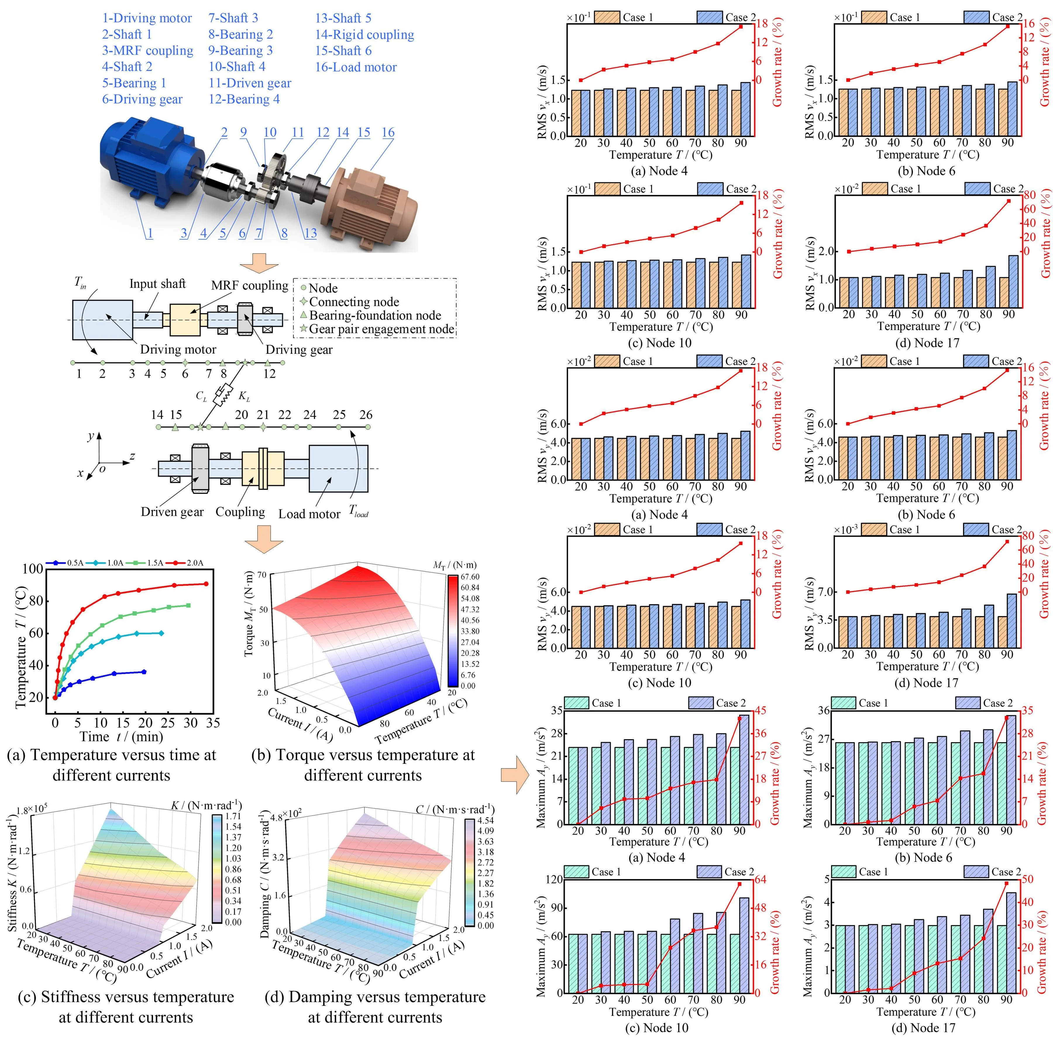
In this study, to reflect the vibration-damping performance of the MRF coupling in the EDGTS more realistically, a mapping relationship between the operating temperature and the mechanical performances of the MRF coupling, such as stiffness, damping, and torque, was constructed. Based on the model of EDGTS with MRF coupling shown in Fig. 1, this study focused on the influence law of the variation in the mechanical performances of the MRF coupling on the dynamical behavior of the EDGTS under different operating temperature environments. The organization of this article is as follows. In Sections 2 and 3, the coupled model of the MRF coupling and the dynamical model of the EDGTS are introduced, respectively. In Section 4, the influences of the MRF coupling on the coupled vibration characteristics of the EDGTS with and without considering the operating temperature environment are compared, and the results of the analysis are discussed. The conclusions of this research are summarized in Section 5.
Fig. 1Three-dimensional model of the EDGTS with MRF coupling
2. Coupled model of MRF coupling
2.1. Torque model of MRF coupling unit
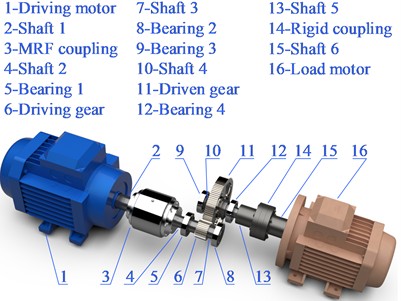
A three-dimensional model of MRF coupling is shown in Fig. 2. The MRF is distributed in the working clearance formed between the driving and driven cylinders, where the former is fixed to the driving motor input shaft and the latter to the driving gear. Initially, when the coil is unenergized, the magnetic particles in the working clearance are free in the carrier fluid. At this point, the torque generated by the MRF zero-field viscosity cannot rotate the driven cylinder. Upon energization of the coil, the MRF converts to a solid-like state, with its magnetic particles aligned into a chain-like structure along the magnetic lines of force. This structure enhances the shear yield stress, which transfers torque and enables the driven cylinder to rotate. After the coil is de-energized, the MRF reverts to a fluid state within a few millimeters, and the MRF coupling returns to its initial state. The stiffness, damping, and torque of the MRF coupling can be adjusted by varying the coil current, thereby regulating the mechanical performances of the MRF coupling and reducing the vibration of the EDGTS.
Fig. 2Three-dimensional model of MRF coupling
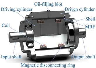
The torque model of MRF coupling is shown in Fig. 3, where the outer radius of the driving cylinder and the inner radius of the driven cylinder are and , respectively, the input and output rotational speeds are and , respectively, is the actual axial length of the MRF between the cylinders, and is the equivalent axial length of the MRF. The torque transmitted by the MRF is [21]:
where is the MRF zero-field viscosity, is the shear yield stress of magnetic particles, which is dependent on variations in the applied magnetic field and temperature.
Fig. 3Torque model of MRF coupling
2.2. Thermodynamical model of MRF coupling unit
When the coil is energized, there is a rotational speed difference between the driving and driven cylinders, resulting in MRF coupling slip operation. By combining Eq. (1), the MRF slip speed can be expressed as:
where is the MRF working clearance width.
Considering the influence of the magnetic flux density, particle size, and coating thickness, the friction between the magnetic particles, cylinder wall, and carrier fluid in the MRF generates slip thermal power, as shown in Eq. (3):
where is the vacuum permeability, is the initial magnetic susceptibility, is the saturation magnetization, is the magnetic-field intensity, is the MRF volume fraction, is the shear strain, is the friction coefficient, is the number of single-chain magnetic particles, is the material correlation constant, is the clearance between particles, and are the magnetic-particle radius and coating thickness, respectively, and , , and are the computational intermediate variables, as shown in Eq. (4):
The slip thermal power of MRF coupling is shown in Fig. 4.
Fig. 4Slip thermal power of MRF coupling
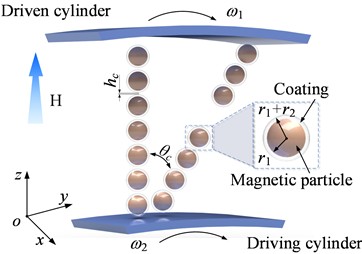
Under slip conditions, the heat of MRF coupling primarily arises from the slip differential heat in the MRF working clearance and the energy loss of the coil. The heat source intensity per unit volume in the MRF working clearance can be expressed as:
where is the volume of the MRF working clearance. The energy loss of the coil is related to the coil current and coil resistance and can be expressed as:
The heat source intensity of the coil can be expressed as:
where the coil inner and outer radii are and , respectively, and the coil width is .
Thermal convection of MRF coupling mainly consists of convective heat transfer between the outer surface of the driven cylinder, the outer surface of the shell, and the coil end faces and the air [27, 28]. Newton’s law of cooling is used to describe the heat transfer equation for the above thermal convection:
where and are the heat transfer coefficient and surface heat transfer area of each component of MRF coupling, respectively.
Assuming that the temperature rise time is and the temperature rise is in time, the heat representation of the energy conservation equation can be obtained by combining Eqs. (5-8):
where, , , and are the heat dissipation power (kW), specific heat capacity, and mass of each component of MRF coupling, respectively.
2.3. Dynamical model of MRF coupling unit
The stiffness and damping of the MRF coupling vary with the solidification degree of the MRF at different magnetic-field intensities, which, in turn, is related to the shear complex modulus. The shear complex modulus of the MRF can be expressed as [29]:
where the real and imaginary parts of the shear complex modulus are the shear energy storage modulus and the shear loss modulus , respectively. The ratio of the two moduli is the loss factor and is generally calculated using the following empirical formula [30].
The relationship between the shear storage modulus, magnetic flux density , and temperature is approximated by fitting [31]:
where = 0.2 Tesla, = 0.6 Tesla. When the zero-field shear energy storage modulus = 0.15 MPa, the variation laws of the shear energy storage and shear loss moduli with magnetic flux density and temperature can be obtained by combining Eqs. (10) and (11), and the results are shown in Fig. 5.
Fig. 5Modulus versus temperature at different magnetic flux densities
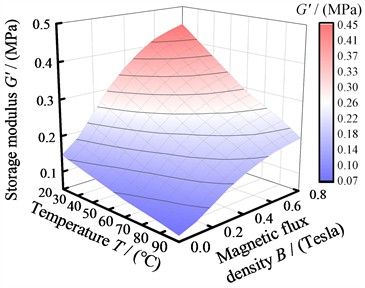
a) Storage modulus
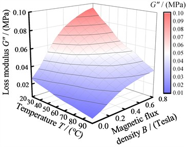
b) Loss modulus
The shear energy storage and shear loss moduli decrease nonlinearly with increasing temperature at different magnetic flux densities. Figs. 5(a) and (b) show that the maximum shear energy storage and shear loss moduli (under a 0.8-Tesla field intensity condition) decrease from 0.45 and 0.09 MPa to 0.20 and 0.04 MPa, respectively, both with a change rate of 55.56 %.
The three main parameters of MRF coupling coupled to the EDGTS are the equivalent torsional stiffness coefficient , equivalent damping coefficient and equivalent moment of inertia , respectively, which can be expressed as [32]:
where and are the mass and equivalent rotary radius of the driven cylinder, respectively. Here, is the damping ratio of the MRF, and is the critical damping coefficient [33].
The torsional stiffness and damping matrices for the MRF coupling unit are and , respectively, with and having the same form. In addition, and are the mass and displacement matrices, respectively, which can be expressed as:
where is the mass of the MRF coupling. The dynamical equation for the MRF coupling unit can be expressed as:
3. Dynamical model of EDGTS
As shown in Fig. 1, the EDGTS is organized into the MRF coupling, driving motor, shaft segment, connecting, bearing-foundation, and gear pair engagement units. The important parameters of the driving motor unit are described in detail elsewhere [34].
3.1. Dynamical model of shaft segment unit
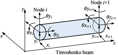
Fig. 6 shows the double nodes of the shaft segment unit are subjected to the bending moments, torsional moments, and axial loads, and its equivalent dynamical model can be established by the Timoshenko beam unit.
The displacement column vector of the double nodes of the shaft segment in the generalized coordinates can be expressed as:
where , , and and , , and are the displacements of nodes and along the local coordinate direction, respectively, and , , and and , , and are the angles of the section around the three coordinate axes at nodes and , respectively. The stiffness matrix for the double nodes of the shaft segment unit can be expressed as:
where specific calculations for , , , and () are available in reference [35].
The mass matrix for the shaft segment unit can be expressed as:
where is the shaft segment density, is the unit cross-sectional area, and is the unit length, respectively.
The damping matrix for the shaft segment unit is commonly derived using Rayleigh damping:
where and are weight coefficients of the mass and stiffness matrices, respectively, and and () are the first two-order natural frequencies and damping coefficients of the shaft segment unit, respectively.
Combining Eqs. (15-18), the dynamical equation for the shaft segment unit can be derived as:
Fig. 6Dynamical model of shaft segment unit
3.2. Dynamical model of connecting unit
The connecting unit equivalent dynamical model consists of nodes and of shaft segment units 1 and 2, as shown in Fig. 7.
Fig. 7Dynamical model of connecting unit
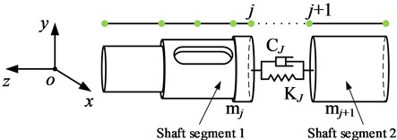
Here, and are the coupled stiffness and damping matrix between nodes and on shaft segment units 1 and 2, respectively, which can be expressed as:
where , , and , are the radial coupled stiffness and damping, respectively, and are the axial coupled stiffness and damping, respectively, and and () are the torsional coupled stiffness and damping in three directions around the generalized coordinates , respectively.
The mass matrix for the connecting unit can be expressed as:
where and are the mass matrices of counterpart nodes and , respectively, and are the masses of the shaft segment units of counterpart nodes and , respectively, and and () are the rotational inertia values of the shaft segment units of the counterpart nodes and , respectively.
The displacement column vector of the connecting unit has the same structural form as in Eq. (15), and the dynamical equation for the connecting unit can be expressed as:
3.3. Dynamical model of bearing-foundation unit
The bearing-foundation unit dynamical model was adopted to reflect the coupling characteristics and vibration transmission law of the bearing support structure accurately, as shown in Fig. 8.
Fig. 8Dynamical model of bearing-foundation unit
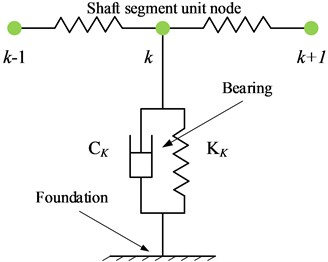
The support stiffness matrix for the bearing-foundation unit can be expressed as:
where , , and are the radial and axial support stiffness values, respectively, and and are the torsional stiffnesses in the direction around the - and -axes of the generalized coordinates, respectively.
The structural form of the bearing support damping matrix remains the same as that of , and the dynamical equation for the bearing-foundation unit is [36]:
where is the displacement column vector of node ofhe shaft segment in six directions.
3.4. Dynamical model of gear pair engagement unit
The dynamical model of the gear pair engagement unit is shown in Fig. 9, and its main parameters are described in Reference [21].
Fig. 9Dynamical model of gear pair engagement unit
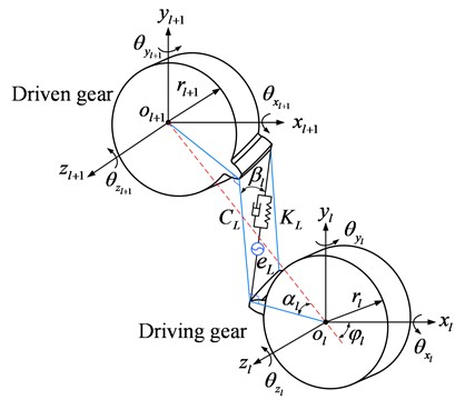
As Fig. 9 shows, the displacement column vector of the gear pair engagement unit node is . By projecting the microdisplacements in each direction to the engagement line, the engagement vector can be obtained:
where and are the base circle radii of the gear pair, respectively, and is the base circle helix angle (positive for dextrorotation and negative for levorotation). Here, is the working pressure angle of the gear pair, and is the angle between the line connecting the centers of the gear pair and the -axis.
The stiffness matrix and damping matrix for the gear pair engagement unit are:
where is the normal composite engagement stiffness, and is the gear pair engagement damping.
The equivalent displacement and velocity column vectors for the composite engagement error after decomposition in each degree of freedom are:
where is the normal composite error of the gear pair. The mass matrix for the gear pair engagement unit is:
where and are the masses of the gear pair, respectively, and , , and () are the rotational inertia of the gear pair around the -axis (), respectively. Combining Eqs. (25-28) yields the following dynamical equation for the gear pair engagement unit:
The engagement impact force column vector is the product of the gear normal impact force and the engagement transpose vector [34].
3.5. Mechanical-electromagnetic-thermal coupled dynamical model
As shown in Fig. 10, each unit of the EDGTS is respectively discretized into separate nodes, which are positioned and numbered sequentially according to the order of each unit. When both axes are divided into 12 units, the MRF coupling is positioned at node 6, the driving and driven gears are positioned at nodes 10 and 17, respectively, and the driving and load torques ( and ) are imposed at nodes 4 and 23, respectively.
Fig. 10Schematic diagram of the discrete nodes of EDGTS
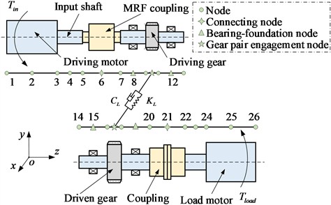
Fig. 11Schematic diagram of the total assembling rules of EDGTS
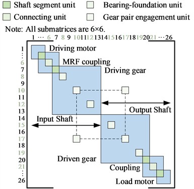
Based on the idea of the classical structural mechanics analysis method, such an infinite degree-of-freedom continuously distributed mechanical vibration system as the EDGTS is translated into a finite degree-of-freedom discrete system. Subsequently, according to the assembly relationship between each unit node and the total nodes of the system, the submatrices of each unit are sequentially filled into the coupled position of the total matrix of the system to assemble the total stiffness matrix for the EDGTS, as shown in Fig. 11. The total mass matrix and damping matrix for the EDGTS are assembled in the same way as described above.
By assembling each basic unit according to the rules shown in Fig. 11, the overall dynamical equation for the EDGTS can be obtained:
where and are the overall displacement column vector and external excitation force (including the driving and load torques) of the EDGTS, respectively. The equivalent displacement column vectors and velocity column vectors of the composite engagement error only have values for the gear pair engagement unit.
4. Result and discussion
4.1. Magnetic-field FEA of MRF coupling
A two-dimensional axisymmetrical model was established to conduct the finite-element analysis (FEA) to characterize the transmission characteristics of MRF couplings more precisely at different currents. As shown in Fig. 12, the materials for each component of the MRF coupling are represented by different colors, and its dimensional design parameters are listed in Table 1.
Fig. 12Two-dimensional axisymmetrical model of the MRF coupling
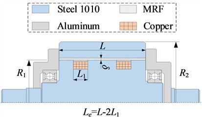
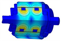
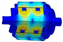
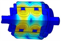
The material of both the driving and driven cylinders is steel 1010 and the material of the shell is aluminum. Considering the magnetisation characteristic of the materials used in the MRF coupling to obtain more accurate magnetic flux and magnetic line of force distributions are shown in Fig. 13.
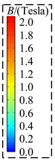
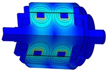
Fig. 13Three-dimensional cloud maps of magnetic flux distribution at different currents
a)0.5 A
b)1.0 A
c)1.5 A
d)2.0 A
Table 1Dimensional design parameters of MRF coupling (mm)
49 | 70 | 100 | 70 | 1 |
At different currents excitation, the direction of the magnetic lines of force passing through is vertical to the MRF shear flow direction, indicating that the MRF coupling is well-designed. When = 0.5 A, the mean value of magnetic flux density in the working clearance is 0.24 Tesla. As the current increases incrementally to 1.0, 1.5, and 2.0 A, the corresponding mean values of magnetic flux density in the working clearance rise to 0.48, 0.66, and 0.77 Tesla, respectively.
Fig. 14Variation of magnetic flux density with distance and current within the MRF working clearance
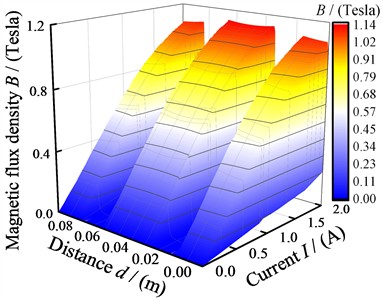
As shown in Fig. 14, the magnetic flux density within the MRF working clearance is uniformly distributed and increases nonlinearly with increasing current. According to the distribution law of magnetic flux density, the maximum flux density is 1.14 Tesla at axial distances = 0.035 and 0.065 m, and the minimum flux density is 0.003 Tesla at axial distances = 0.025 and 0.075 m.
4.2. Thermal-field FEA of MRF coupling
The temperature distribution of MRF coupling was analysed using a thermal-field FEA model, which is identical to the magnetic-field FEA model shown in Fig. 12. The material thermodynamic parameters of MRF coupling are listed in Table 2.
Table 2Thermodynamic parameters of materials
Materials | Steel 1010 | Copper | Aluminum | MRF |
Density (kg/m3) | 7800 | 8500 | 2700 | 3200 |
Specific heat (J/(kg·℃)) | 500 | 377 | 880 | 1000 |
Thermal conductivity (W/(m·℃)) | 46.4 | 106 | 217.7 | 0.835 |
In this study, and are taken as the main heat sources of MRF coupling and are calculated using Eqs. (5) and (7), respectively. The heat transfer coefficients of each MRF coupling component are shown in Table 3.
Table 3Heat transfer coefficient of every component of the MRF coupling
Component | Heat transfer coefficient (W/(m2·℃)) |
Bearing | 56.23 |
Thermal radiation | 16.36 |
End face of coil | 132.36 |
Rotating surface of driven cylinder | 365.68 |
Rotating surface of driving cylinder | 392.86 |
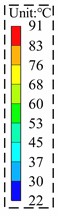
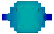
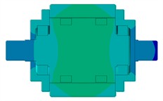
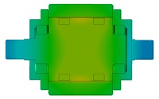
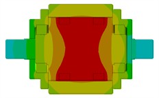
As shown in Fig. 15, the average temperatures of the driving and driven cylinders are 80.53 °C and 69.04 °C, respectively, when = 2.0 A. The maximum MRF coupling temperature (91 °C) is located at the geometrical center of the MRF working clearance between the two coils because of the low thermal conductivity and high thermal resistance of this area. Meanwhile, the lowest MRF coupling temperature (39 °C) is at the end of the output shaft.
Fig. 15Temperature distribution cloud maps of the MRF coupling unit under varied currents
a)0.5 A
b)1.0 A
c)1.5 A
d)2.0 A
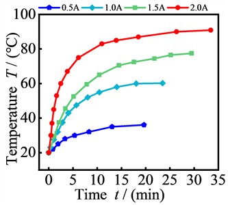
Fig. 16Effects of current on the MRF working clearance temperatures: a)-d) temperature distribution cloud maps of the MRF working clearances under varied currents, and e) relationship between operating temperature and time of MRF at different currents

a)0.5 A

b)1.0 A

c)1.5 A

d)2.0 A

e)
A temperature distribution cloud map of the MRF working clearances is shown in Figs. 16(a-d). Taking = 1.5 A as an example. The temperature is symmetrically distributed along the radial centerline of the MRF working clearance and gradually decreases along the axial centerline to both sides. When the temperature at the geometrical center of the MRF working clearance reaches 69 °C, the temperature on both sides of the MRF working clearance is 55.35 °C. As shown in Fig. 16(e), the maximum steady-state temperatures of the MRF working clearance at different currents are 36.10 °C, 60.20 °C, 77.50 °C, and 90.90 °C. The corresponding temperature rise times are 19.67 min, 23.47 min, 29.48 min, and 33.42 min, respectively.
Fig. 17MRF coupling torque versus temperature at different currents
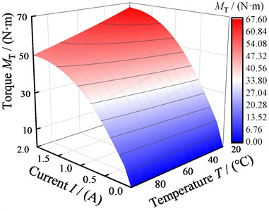
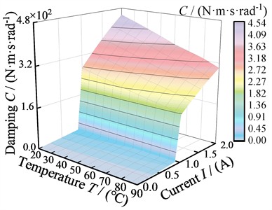
The variation law of the MRF coupling torque with current and temperature is shown in Fig. 17. The torque generated by the MRF coupling increases with increasing current at any constant temperature. The shear yield stress of the MRF increases nonlinearly with the current. As a result, the current-torque curve also demonstrates a high degree of nonlinearity. When = 20 °C, the MRF coupling can generate a torque of 12.40 N·m at a current of 0.125 A. As the current increases to 1.625 A, the torque rapidly increases to 65.41 N·m. However, as the current continues to increase, the magnetic saturation characteristic of the MRF slows the growth rate of the shear yield stress, resulting in a plateau in the torque growth trend. When =2.0 A, the rheological properties of the MRF, including the shear yield stress and viscosity, decrease significantly as the temperature rises from 20 to 90 °C. The torque decreases from 67.44 to 50.21 N·m, representing a reduction rate of 25.55 %. Therefore, it is essential to research the impact of the operating temperature on the MRF transmission performance during system operation.
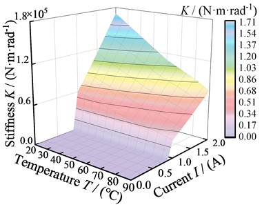
Fig. 18Dynamical parameters of the MRF coupling versus temperature at different currents
a) Stiffness curve of MRF
b) Damping curve of MRF
When 2.0 A, the stiffness and damping decrease from 1.71×10⁵ and 4.52×10² N·m·s·rad−1 to 0.76×10⁵ and 3.01×10² N·m·s·rad−1, respectively, as the temperature rises from 20 to 90 °C. The reduction rates are 53.56 % and 33.41 %, respectively. The solidification characteristic of the MRF changes with the current, and its stiffness and damping increase exponentially with the current. For instance, at 90 °C, the maximum stiffness and damping are 1.08×10² N·m·rad−1 and 11.38 N·m·s·rad−1, respectively, when the current is in the range of 0~0.875 A. Subsequently, when the current surpasses 0.875 A, the maximum stiffness and damping surge to 0.76×10⁵ N·m·rad−1 and 3.01×10² N·m·s·rad−1. This is because of the significant increase in the apparent viscosity of the MRF when subjected to an applied magnetic field. Consequently, the stiffness and damping increase several hundred times [21].
4.3. Coupled vibration characteristics of EDGTS
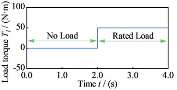
To analyze the influence law of MRF coupling on the coupled vibration characteristics of the EDGTS under multiple excitations, a step load excitation was applied. As Fig. 19 shows, the load torque of the system abruptly increased from 0 to 50 N·m at 2.0 s.
Fig. 19Step loads applied to the EDGTS
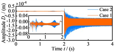
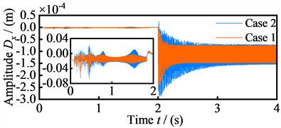
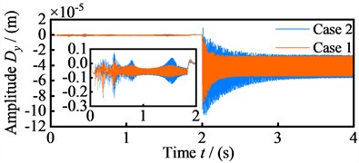
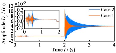
Numerical simulations were performed to analyze the dynamical behaviors of the EDGTS both with and without considering the operating temperature of the MRF coupling (cases 2 and 1, respectively). According to the results of the thermal-field analysis in Section 4.2, the operating temperature of the MRF coupling reached its maximum value under 2.0 A current excitation, resulting in the most significant attenuation of its vibration-damping performance. To ensure generality, 2.0 A current was used as the excitation power source for the MRF coupling in the following. The variation laws of the vibration displacement amplitudes of the motor input shaft node (node 4), MRF coupling (node 6), driving gear (node 10), and driven gear node (node 17) under the temperature influence were investigated.
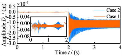
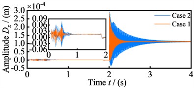
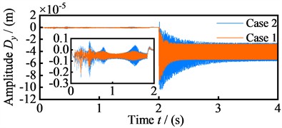
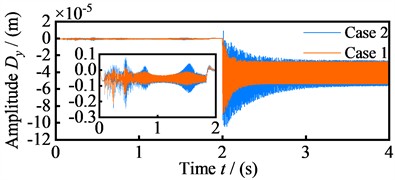
Figs. 20 and 21 show the time-domain variation laws of the vibration displacement amplitudes of the four nodes of EDGTS in the x and y directions for the no-load (0-2.0 s) and rated-load operation (2.0-4.0 s) phases of the two cases, respectively. During 0-2.0 s phase, the system vibration increases after motor startup but stabilizes after 0.8 s. In case 1, the amplitude ranges of the four nodes in the x-direction are –0.06~0.01×10⁻⁴ m, –0.06~0.01×10⁻⁴ m, –0.06~0.01×10⁻⁴ m, and –0.04~0.05×10⁻⁴ m, respectively. In the y-direction, the amplitude ranges are –0.22~0.03×10⁻⁵ m, –0.22~0.03×10⁻⁵ m, –0.22~0.03×10⁻⁵ m, and –0.13~0.19×10⁻⁵ m, respectively. In case2, the amplitude of vibration displacements increased, and the amplitude ranges of the four nodes in the -direction are –0.07~0.02×10⁻⁴ m, –0.07~0.02×10⁻⁴ m, –0.07~0.02×10⁻⁴ m, and –0.05~0.08×10⁻⁴ m, respectively. ln the -direction, the amplitude ranges are –0.25~0.08×10⁻⁵ m, –0.24~0.08×10⁻⁵ m, –0.25~0.08×10⁻⁵ m, and –0.17~0.28×10⁻⁵ m, respectively. After 2.0 s, the amplitude ranges of the four nodes of case 1 in the -direction are –2.42~0.01×10⁻⁴ m, –2.43~0.01×10⁻⁴ m, –2.44~0.01×10⁻⁴ m, and –0.06~2.86×10⁻⁴ m, respectively. The amplitude ranges of the four nodes in the -direction are –8.82~0.01×10⁻⁵ m, –8.85~0.01×10⁻⁵ m, –8.88~0.01×10⁻⁵ m, and –0.21~10.42×10⁻⁵ m, respectively. As the operating temperature increases the mechanical properties of the MRF decrease, resulting in a significant increase in the range of vibration displacement amplitudes of the system. In case2, the amplitude ranges of the four nodes in the -direction are –2.85~0.25×10⁻⁴ m, –2.87~0.25×10⁻⁴ m, –2.88~0.24×10⁻⁴ m, and -0.36~2.93×10⁻⁴ m, with growth rates of 27.57 %, 27.87 %, 27.35 %, and 12.67 %, respectively. The amplitude ranges in y-direction are –10.38~0.91×10⁻⁵ m, –10.43~0.89×10⁻⁵ m, –10.48~0.88×10⁻⁵ m, and –1.29~10.67×10⁻⁵ m, with growth rates of 27.86 %, 27.77 %, 27.78 %, and 12.51 %, respectively.
Fig. 20Vibration displacement amplitude of the four nodes in the x-direction
a) Node 4
b) Node 6
c) Node 10
d) Node 17
Fig. 21Vibration displacement amplitude of the four nodes in the y-direction
a) Node 4
b) Node 6
c) Node 10
d) Node 17
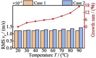
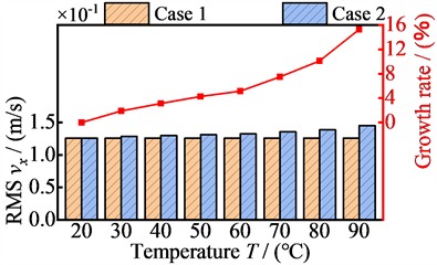
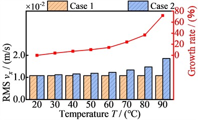
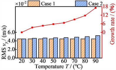
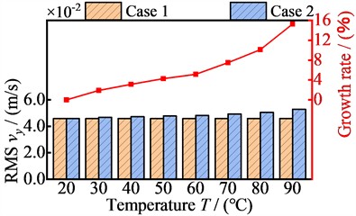
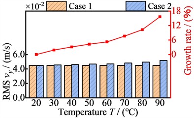
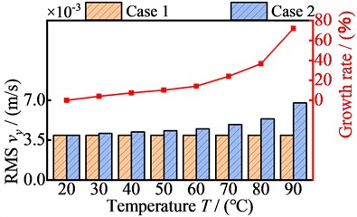
Figs. 22 and 23 show the variation laws of the vibration velocity RMS values with temperature for the four nodes in the and directions, respectively. The vibration velocity RMS values of each node in the EDGTS increase with the rise of the operating temperature. When the operating temperature increases from 20 °C to 90 °C, the RMS values of the four nodes in the -direction increase from 1.22×10⁻¹ m/s, 1.26×10⁻¹ m/s, 1.23×10⁻¹ m/s, and 1.08×10⁻² m/s to 1.44×10⁻¹ m/s, 1.45×10⁻¹ m/s, 1.42×10⁻¹ m/s, and 1.86×10⁻² m/s, with growth rates of 17.09 %, 15.28 %, 15.67 %, and 72 %, respectively. In the -direction, the RMS values increase from 4.47×10⁻² m/s, 4.58×10⁻² m/s, 4.48×10⁻² m/s, and 3.93×10⁻³ m/s to 5.24×10⁻² m/s, 5.28×10⁻² m/s, 5.18×10⁻² m/s, and 6.75×10⁻³ m/s, with growth rates of 17.09 %, 15.28 %, 15.67 %, and 72 %, respectively. The variation laws of the vibration velocity RMS values in the and directions remain consistent, and the vibration of node 17 in these two directions increases significantly when the temperature rises to 90 °C, with a growth rate of 72 %. The above results show that the rise in operating temperature has an inhibitory effect on the vibration-damping performance of the MRF coupling, which in turn affects the operating efficiency and work stability of the EDGTS.
Fig. 22The relationship between vibration velocity RMS values of four nodes in the x-direction and temperature
a) Node 4
b) Node 6

c) Node 10
d) Node 17
Fig. 23The relationship between vibration velocity RMS values of four nodes in the y- direction and temperature
a) Node 4
b) Node 6
c) Node 10
d) Node 17
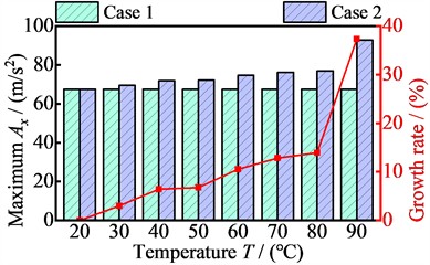
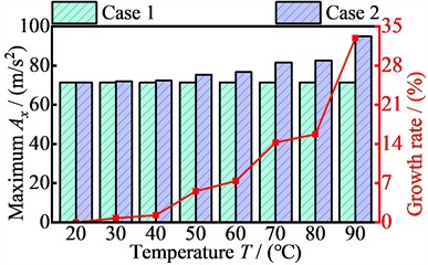
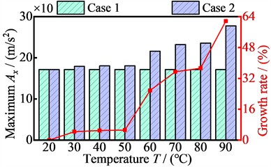
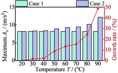
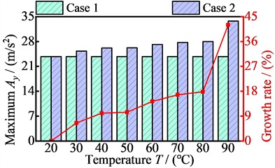
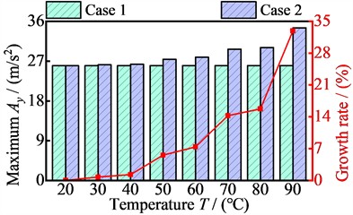
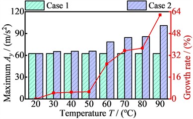
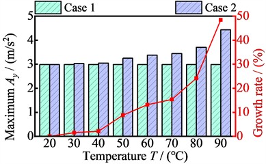
Figs. 24 and 25 show the variation laws of the vibration acceleration maximum values with temperature for the four nodes in the and directions, respectively. The vibration acceleration maximum values of each node in the EDGTS is positively correlated with the operating temperature.
Fig. 24The relationship between vibration acceleration maximum values of four nodes in the x-direction and temperature
a) Node 4
b) Node 6
c) Node 10
d) Node 17
Fig. 25The relationship between vibration acceleration maximum values of four nodes in the y-direction and temperature
a) Node 4
b) Node 6
c) Node 10
d) Node 17
As the operating temperature rises from 20 °C to 90 °C, the maximum values of the four nodes in the -direction increase from 67.54 m/s2, 71.40 m/s2, 171.59 m/s2, and 8.20 m/s2 to 92.75 m/s2, 94.91 m/s2, 277.33 m/s2, and 12.17 m/s2, with growth rates of 37.33 %, 32.92 %, 61.63 %, and 48.45 %, respectively. In the y-direction, the maximum values increase from 23.77 m/s2, 25.99 m/s2, 62.45 m/s2, and 2.98 m/s2 to 33.76 m/s2, 34.54 m/s2, 100.94 m/s2, and 4.43 m/s2, with growth rates of 42.02 %, 32.93 %, 61.62 %, and 48.45 %, respectively. As the temperature of the MRF rises, the base fluid then evaporates and irreversible thickening phenomenon occurs. This leads to a reduction in the vibration-damping performance of the MRF coupling, and deterioration in stability and working accuracy. The vibration amplitude of the EDGTS is exacerbated, affecting the service life of the system components. The most significant increase in the vibration acceleration maximum value of node 10 in the -direction is observed when the temperature increases to 90 °C, with a value of 61.63 %.
5. Conclusions
A mechanical-electromagnetic-thermal coupled dynamical model of an EDGTS containing an MRF coupling unit was developed by introducing the microscale particle heat transfer theory, and the influences of operating temperature variation on the MRF coupling mechanical performances and the dynamics behavior of the EDGTS were investigated. The results of this study are as follows.
1) The shear energy storage and shear loss moduli of the MRF coupling decrease gradually as the operating temperature increases. When the current is 2.0 A and the operating temperature reaches 90 °C, the two moduli of MRF coupling decrease the most, from 0.45 and 0.09 MPa to 0.20 and 0.04 MPa, respectively, and the change rates are both 55.56 %. Meanwhile, with the increase in operating temperature, the torque, stiffness, and damping of the MRF coupling unit decrease from 67.44 N·m, 1.71×10⁵ N·m·rad-1, and 4.52×10²N·m·s·rad-1 to 50.21 N·m, 0.76×10⁵ N·m·rad-1, and 3.01×10²N·m·s·rad-1, with change rates of 25.55 %, 53.56 % and 33.41 %, respectively.
2) After considering the effect of operating temperature on the MRF coupling, the vibration displacement amplitude range at each node of the EDGTS increases significantly. During the rated-load operation phases, the vibration displacement amplitude ranges of the four nodes in the -direction increases from –2.42~0.01×10⁻⁴ m, –2.43~0.01×10⁻⁴ m, –2.44~0.01×10⁻⁴ m, and –0.06~2.86×10⁻⁴ m to –2.85~0.25×10⁻⁴ m, –2.87~0.25×10⁻⁴ m, –2.88~0.24×10⁻⁴ m, and –0.36~2.93×10⁻⁴ m, respectively. The amplitude ranges of the four nodes in the y-direction increases from –8.82~0.01×10⁻⁵ m, –8.85~0.01×10⁻⁵ m, –8.88~0.01×10⁻⁵ m, and –0.21~10.42×10⁻⁵ m to –10.38~0.91×10⁻⁵ m, –10.43~0.89×10⁻⁵ m, –10.48~0.88×10⁻⁵ m, and –1.29~10.67×10⁻⁵ m, respectively. Node 6 has the largest growth rate in the vibration displacement amplitude range in the -direction, with a value of 27.87 %.
3) The vibration velocity RMS values and vibration acceleration maximum values at each node of the EDGTS increase with the rise in operating temperature. The growth rate of the vibration displacement RMS values of the four nodes in -direction is 17.09 %, 15.28 %, 15.67 %, and 72 %, respectively. The growth rate in -direction is 17.09 %, 15.28 %, 15.67 %, and 72 %, respectively. Meanwhile, the growth rate of the vibration acceleration maximum values of the four nodes in the -direction is 37.33 %, 32.92 %, 61.63 %, and 48.45 %, respectively. The growth rate of the maximum values in the -direction is 42.02 %, 32.93 %, 61.62 %, and 48.45 %, respectively.
4) This study is limited by discrepancies between the model assumptions (such as uniform MRF material parameters and constant thermal boundary conditions) and actual operating conditions, and it lacks experimental validation. Future work should involve validating the model through experimental testing and integrating temperature sensors with adaptive current control strategies to compensate for MRF temperature-induced performance degradation in real time.
References
-
W. Bai, D. Qin, Y. Wang, and T. C. Lim, “Dynamic characteristic of electromechanical coupling effects in motor-gear system,” Journal of Sound and Vibration, Vol. 423, pp. 50–64, Jun. 2018, https://doi.org/10.1016/j.jsv.2018.02.033
-
J. Tan, C. Zhu, C. Song, and X. Xu, “Study on the dynamic modeling and natural characteristics of wind turbine drivetrain considering electromagnetic stiffness,” Mechanism and Machine Theory, Vol. 134, pp. 541–561, Apr. 2019, https://doi.org/10.1016/j.mechmachtheory.2019.01.015
-
X. Chen, J. Hu, K. Chen, and Z. Peng, “Modeling of electromagnetic torque considering saturation and magnetic field harmonics in permanent magnet synchronous motor for HEV,” Simulation Modelling Practice and Theory, Vol. 66, pp. 212–225, Aug. 2016, https://doi.org/10.1016/j.simpat.2016.02.012
-
X. Chen, H. Wei, T. Deng, Z. He, and S. Zhao, “Investigation of electromechanical coupling torsional vibration and stability in a high-speed permanent magnet synchronous motor driven system,” Applied Mathematical Modelling, Vol. 64, pp. 235–248, Dec. 2018, https://doi.org/10.1016/j.apm.2018.07.030
-
C. Xiang, F. Liu, H. Liu, L. Han, and X. Zhang, “Nonlinear dynamic behaviors of permanent magnet synchronous motors in electric vehicles caused by unbalanced magnetic pull,” Journal of Sound and Vibration, Vol. 371, pp. 277–294, Jun. 2016, https://doi.org/10.1016/j.jsv.2016.02.015
-
T. Szolc, R. Konowrocki, M. Michajłow, and A. Pręgowska, “An investigation of the dynamic electromechanical coupling effects in machine drive systems driven by asynchronous motors,” Mechanical Systems and Signal Processing, Vol. 49, No. 1-2, pp. 118–134, Dec. 2014, https://doi.org/10.1016/j.ymssp.2014.04.004
-
Y. A. Amer, A. T. El-Sayed, and E. E. E. Ahmed, “Vibration reduction of vertical conveyor system via negative cubic velocity feedback under external and parametric excitations,” Journal of Mechanical Science and Technology, Vol. 36, No. 2, pp. 543–551, Feb. 2022, https://doi.org/10.1007/s12206-022-0103-0
-
Z. Chen, W. Zhai, and K. Wang, “A locomotive-track coupled vertical dynamics model with gear transmissions,” Vehicle System Dynamics, Vol. 55, No. 2, pp. 244–267, Nov. 2016, https://doi.org/10.1080/00423114.2016.1254260
-
J.-F. Shi, X.-F. Gou, and L.-Y. Zhu, “Modeling and analysis of a spur gear pair considering multi-state mesh with time-varying parameters and backlash,” Mechanism and Machine Theory, Vol. 134, pp. 582–603, Apr. 2019, https://doi.org/10.1016/j.mechmachtheory.2019.01.018
-
C. Siyu and T. Jinyuan, “Effects of staggering and pitch error on the dynamic response of a double-helical gear set,” Journal of Vibration and Control, Vol. 23, No. 11, pp. 1844–1856, Sep. 2015, https://doi.org/10.1177/1077546315601936
-
Z. Hu, J. Tang, J. Zhong, S. Chen, and H. Yan, “Effects of tooth profile modification on dynamic responses of a high speed gear-rotor-bearing system,” Mechanical Systems and Signal Processing, Vol. 76-77, pp. 294–318, Aug. 2016, https://doi.org/10.1016/j.ymssp.2016.01.020
-
J. Wei et al., “A study of nonlinear excitation modeling of helical gears with Modification: Theoretical analysis and experiments,” Mechanism and Machine Theory, Vol. 128, pp. 314–335, Oct. 2018, https://doi.org/10.1016/j.mechmachtheory.2018.06.005
-
J. Xi, X. Dong, W. Li, T. Wang, X. Song, and Z. Zhang, “A novel passive adaptive magnetorheological energy absorber,” Smart Materials and Structures, Vol. 30, No. 1, p. 014001, Jan. 2021, https://doi.org/10.1088/1361-665x/abc149
-
S. R. Patil, K. P. Powar, and S. M. Sawant, “Thermal analysis of magnetorheological brake for automotive application,” Applied Thermal Engineering, Vol. 98, pp. 238–245, Apr. 2016, https://doi.org/10.1016/j.applthermaleng.2015.11.128
-
K.-H. Lee, J.-E. Park, and Y.-K. Kim, “Design of a stiffness variable flexible coupling using magnetorheological elastomer for torsional vibration reduction,” Journal of Intelligent Material Systems and Structures, Vol. 30, No. 15, pp. 2212–2221, Jul. 2019, https://doi.org/10.1177/1045389x19862378
-
S. S. Sun et al., “Development of an isolator working with magnetorheological elastomers and fluids,” Mechanical Systems and Signal Processing, Vol. 83, pp. 371–384, Jan. 2017, https://doi.org/10.1016/j.ymssp.2016.06.020
-
H. K. Kim, H. S. Kim, and Y.-K. Kim, “Stiffness control of magnetorheological gels for adaptive tunable vibration absorber,” Smart Materials and Structures, Vol. 26, No. 1, p. 015016, Jan. 2017, https://doi.org/10.1088/1361-665x/26/1/015016
-
L. Deng et al., “Experimental testing and modelling of a rotary variable stiffness and damping shock absorber using magnetorheological technology,” Journal of Intelligent Material Systems and Structures, Vol. 30, No. 10, pp. 1453–1465, Mar. 2019, https://doi.org/10.1177/1045389x19835955
-
P. Gao, C. Xiang, H. Liu, and H. Zhou, “Reducing variable frequency vibrations in a powertrain system with an adaptive tuned vibration absorber group,” Journal of Sound and Vibration, Vol. 425, pp. 82–101, Jul. 2018, https://doi.org/10.1016/j.jsv.2018.03.034
-
X. Dong et al., “Magneto-Rheological Variable Stiffness and Damping Torsional Vibration Control of Powertrain System,” Frontiers in Materials, Vol. 7, p. 121, May 2020, https://doi.org/10.3389/fmats.2020.00121
-
H. Gong et al., “Dynamic response analysis of a motor-gear transmission system considering the rheological characteristics of magnetorheological fluid coupling,” Nonlinear Dynamics, Vol. 111, No. 15, pp. 13781–13806, Jun. 2023, https://doi.org/10.1007/s11071-023-08585-6
-
Y. Rabbani, N. Hajinajaf, and O. Tavakoli, “An experimental study on stability and rheological properties of magnetorheological fluid using iron nanoparticle core-shell structured by cellulose,” Journal of Thermal Analysis and Calorimetry, Vol. 135, No. 3, pp. 1687–1697, Jul. 2018, https://doi.org/10.1007/s10973-018-7538-7
-
X. Zhang, R. Wu, K. Guo, P. Zu, and M. Ahmadian, “Dynamic characteristics of magnetorheological fluid squeeze flow considering wall slip and inertia,” Journal of Intelligent Material Systems and Structures, Vol. 31, No. 2, pp. 229–242, Dec. 2019, https://doi.org/10.1177/1045389x19888781
-
Y. Wan, Y. Xiong, and S. Zhang, “Temperature dependent dynamic mechanical properties of Magnetorheological elastomers: Experiment and modeling,” Composite Structures, Vol. 202, pp. 768–773, Oct. 2018, https://doi.org/10.1016/j.compstruct.2018.04.010
-
C. Bharathi Priya and N. Gopalakrishnan, “Temperature dependent modelling of magnetorheological (MR) dampers using support vector regression,” Smart Materials and Structures, Vol. 28, No. 2, p. 025021, Feb. 2019, https://doi.org/10.1088/1361-665x/aae5f0
-
A. Kumar Kariganaur, H. Kumar, and M. Arun, “Influence of temperature on magnetorheological fluid properties and damping performance,” Smart Materials and Structures, Vol. 31, No. 5, p. 055018, May 2022, https://doi.org/10.1088/1361-665x/ac6346
-
H. Gong, Y. Xiong, and J. Huang, “Analysis of electromagnetic-thermal coupling braking properties of combined electromagnetic friction and shape memory alloy brake,” Smart Materials and Structures, Vol. 31, No. 10, p. 105027, Oct. 2022, https://doi.org/10.1088/1361-665x/ac909d
-
J. Zheng, “Study on magnetorheological transmission theory and experiments,” Chongqing University, 2008.
-
N. Hoang, N. Zhang, and H. Du, “An adaptive tunable vibration absorber using a new magnetorheological elastomer for vehicular powertrain transient vibration reduction,” Smart Materials and Structures, Vol. 20, No. 1, p. 015019, Jan. 2011, https://doi.org/10.1088/0964-1726/20/1/015019
-
N. Hoang, N. Zhang, and H. Du, “A dynamic absorber with a soft magnetorheological elastomer for powertrain vibration suppression,” Smart Materials and Structures, Vol. 18, No. 7, p. 074009, Jul. 2009, https://doi.org/10.1088/0964-1726/18/7/074009
-
W. Zhang, X. Gong, S. Xuan, and W. Jiang, “Temperature-dependent mechanical properties and model of magnetorheological elastomers,” Industrial and Engineering Chemistry Research, Vol. 50, No. 11, pp. 6704–6712, 2011, https://doi.org/10.1021/ie200386x
-
M. J. García Tárrago, L. Kari, J. Viñolas, and N. Gil-Negrete, “Torsion stiffness of a rubber bushing: a simple engineering design formula including the amplitude dependence,” The Journal of Strain Analysis for Engineering Design, Vol. 42, No. 1, pp. 13–21, Jan. 2007, https://doi.org/10.1243/03093247jsa246
-
M. Kallio, The Elastic and Damping Properties of Magnetorheological Elastomers. America: VTT Publications, 2005.
-
R. Shu, J. Wei, R. Tan, X. Wu, and B. Fu, “Investigation of dynamic and synchronization properties of a multi-motor driving system: theoretical analysis and experiment,” Mechanical Systems and Signal Processing, Vol. 153, p. 107496, May 2021, https://doi.org/10.1016/j.ymssp.2020.107496
-
L. A. Chang, “Generalized dynamic model for parallel shaft gear transmissions and the influences of dynamic excitations,” Northwestern Polytechnical University, 2014.
-
Y. Qi, J. Wang, H. Dai, S. Luo, Y. Zheng, and H. Jing, “Research on the effect of vertical installation angle and layout of anti-yaw damper on the dynamic performance of high-speed EMUs,” Journal of Vibration and Control, pp. 1–15, 2026, https://doi.org/10.1177/10775463261424829
About this article

This research is supported by Open Fund of State Key Laboratory of Intelligent Mining Equipment Technology (Grant No. ZNCKKF20240109); Science and Technology Research Program of Chongqing Municipal Education Commission (Grant No. KJQN202401147); the National Natural Science Foundation of China (Grant No. 52275052) and Natural Science Foundation of Chongqing (Grant No. CSTB2022NSCQ-MSX0475).
The datasets generated during and/or analyzed during the current study are available from the corresponding author on reasonable request.
Chongyang Zhang: conceptualization, formal analysis. Zanhan Yin: writing-original draft preparation, methodology, investigation, visualization. Haodong Wei: data curation. Huajian Long: validation. Ruizhi Shu: supervision and funding acquisition. Rulong Tan: resources and funding acquisition.
The authors declare that they have no conflict of interest.

