Abstract
This study investigates the vibrational stability and torsional vibration characteristics of an integrated electric drive system composed of a permanent magnet synchronous motor (PMSM) and a two-stage gear pair under parametric excitation. An electromechanically coupled nonlinear torsional dynamic model is established, incorporating electromagnetic effects and time-varying mesh stiffness. The method of multiple scales is employed to analyze the parametric excitation-induced vibrational stability of the system, and the Runge-Kutta method is used to solve the vibrational differential equations and examine the dynamic response characteristics. The results indicate that the system exhibits significant coupled vibrational behavior: the spectrum of the dynamic meshing force contains not only the meshing frequency of the current gear pair but also the system’s natural frequencies and meshing frequency components from other gear stages. Under conditions without external excitation, the system is found to exhibit not only primary resonance responses due to time-varying mesh stiffness excitation but also various nonlinear vibrational phenomena such as subharmonic resonance, superharmonic resonance, and combination resonance. The response is particularly pronounced near twice the first-order natural frequency.
Highlights
- The study demonstrates that the dynamic response spectrum of a single gear pair contains not only its own meshing frequency but also the meshing frequencies of other stages and the system's natural frequencies. This reveals the multi-frequency coupling vibration phenomena within the system.
- The research clearly quantifies that the dynamic load coefficient of the high-speed gear pair is significantly greater than that of the low-speed stage. This key finding directly identifies the dynamic weak point of the system, providing crucial guidance for targeted design improvements.
- The study reveals a spectrum of resonance phenomena—including primary, subharmonic, superharmonic, and combination resonances—triggered by time-varying mesh stiffness. This explains the peaks in the dynamic load coefficient and provides a theoretical basis for avoiding resonance risks.
1. Introduction
The gear train within the reducer achieves speed reduction, converting the high-speed rotation of the motor or other power source into low-speed, high-torque output. It is widely used in fields such as automotive, construction machinery, and aerospace. The integration of the reducer and motor can reduce weight and volume of the system, lower manufacturing costs, and enhance power density. However, this integration also results in complex torsional vibrations due to the coupled excitation of electromagnetic forces and gear meshing. Therefore, studying the vibration characteristics of the integrated system is of significant importance.
Many studies have investigated the vibration response characteristics of gear systems arising from factors such as gear clearances, errors, and time-varying meshing stiffness. Shen et al. [1] developed a dynamic model of a spur gear pair considering time-varying stiffness and clearance, and analyzed the effects of multiple harmonics on periodic solutions using numerical method and the incremental harmonic balance method. Khabou et al. [2] employed the Newmark method to compute the dynamic response, performed a parameter study on spur gears driven by motors and engines, and discussed how speed variations influence the system's vibration characteristics.
Han et al. [3] employed an improved interval harmonic balance method to investigate the dynamics of a single-mesh gear system, incorporating the nonlinear effects of backlash and time-varying meshing stiffness, and examined the influence of parameter uncertainties on the system’s vibration characteristics. Chen et al. [4] developed a nonlinear dynamic model of gear pairs that accounts for microscopic tooth surface features, and analyzed the effects of tooth surface roughness, viscous damping, and meshing stiffness on the dynamic behavior of the gear transmission.
Cao et al. [5] proposed a dynamic model for spur gears considering the influence of load-dependent time-varying meshing stiffness, backlash, and tooth profile deviation. The predicted response of the model was validated against experimental results. To account for axial deviation as an interval parameter in dynamic response analysis, Hu et al. [6] employed an interval analysis method based on the Chebyshev inclusion function to investigate the excitation effect of shaft alignment uncertainty on gear systems.
Extensive research has been conducted on parametric instability in gear systems induced by time-varying meshing stiffness. Parker et al. [7-9] analyzed instability in two-stage gears, planetary gears, and idler gear systems using the asymptotic perturbation method, and revealed the influence of key parameters on the instability regions and vibration response. Rao et al. [10] incorporated both time-varying meshing stiffness and shaft torsional flexibility to investigate torsional instability in a two-stage gear system. The instability regions of the gear system were analyzed using the multi-scale method, and the results were validated through numerical calculations.
Liu et al. [11] developed a dynamic model that accounts for time-varying stiffness of bearings and gear pairs, and investigated the parametric instability induced by the combined fluctuations in stiffness. Gawande et al. [12-13] used a two-stage gear train to identify specific operating conditions leading to parametric instability. The influence of meshing stiffness parameters –including mesh frequency, amplitude of stiffness variation, and mesh phasing contact ratio – on these instabilities was analyzed. The analysis was verified through numerical solution, demonstrating that replacement gear pairs with appropriate mesh phasing can eliminate the instability regions originally present in the two gear pairs of the two-stage gear transmission system. Beinstingel et al. [14] conducted experimental and numerical studies on the vibration behavior of high-speed planetary gearboxes. Using a rotating lumped parameter model with time-varying gear meshing stiffness, they theoretically investigated instability phenomena and experimentally confirmed the occurrence of parametric instability in planetary gearboxes.
Electromechanical coupling and nonlinear effects in permanent magnet synchronous motors (PMSMs) significantly influence NVH performance and operational safety. Chen et al. [15] established a nonlinear PMSM model that accounts for the unbalanced magnetic pull caused by nonuniform magnetic fields, analyzed and obtained approximate solutions to the vibration equation, and discussed the instability characteristics of the system's vibration response. Shin et al. [16] developed an analytical solution for the magnetic field produced by permanent magnets in PMSMs, analyzed electromagnetic vibration sources such as torque ripple, cogging torque, and radial force density, investigated the motor's vibration characteristics and experimentally validated these findings via vibration tests.
Liu et al. [17] developed a rotor-bearing system model considering unbalanced magnetic pull and rotor eccentricity, using multi-scale perturbation methods to study solution instability. Yang et al. [18] used both finite element and analytical methods to investigate the relationship between electromagnetic forces and vibration modes. Wu et al. [19] proposed a multi-physics model to study motor vibration mechanisms and the influence of current harmonics. Sheng et al. [20, 21] established an electromechanically coupled torsional dynamic model for PMSM rotor systems, studied the system using multi-scale and numerical methods.
While significant research efforts have been devoted to individual motor or gear systems, the coupled vibration phenomena in integrated electric drive systems have received comparatively less attention. Hu et al. [22] developed a transient dynamic model of an integrated system comprising a helical gear transmission and a PMSM, and proposed an active vibration reduction strategy to minimize gear mesh force and dynamic load. Yi et al. [23] established a dynamic model of a motor-driven multistage gear system and analyzed the influence of electromagnetic effects on natural characteristics of the gearbox. Liu et al. [24] investigated the effect of load conditions on natural frequency, vibration modes, and motor current in electric vehicle drive systems under electromagnetic excitations.
This paper focuses on the dynamic behavior of integrated system that consists of a permanent magnet synchronous motor (PMSM) and a two-stage gear train. Considering the influence of the torque angle on the motor's back electromotive force, an analytical expression for the electromagnetic torque is derived using energy principles. A nonlinear torsional dynamic model is established that incorporates both the motor and the gear transmission.
The stability of parametric vibrations induced by time-varying meshing stiffness is analyzed using the multi-scale method. The differential equation of the system is solved numerically via the Runge-Kutta method, and the dynamic characteristics of the elastic meshing force are discussed in both the time domain and the frequency domain. The variations of the dynamic load coefficients for each gear pair with respect to excitation frequency are examined, and the relationship between peak positions and the system’s natural frequencies is discussed.
2. Dynamic model of integrated electric drive system
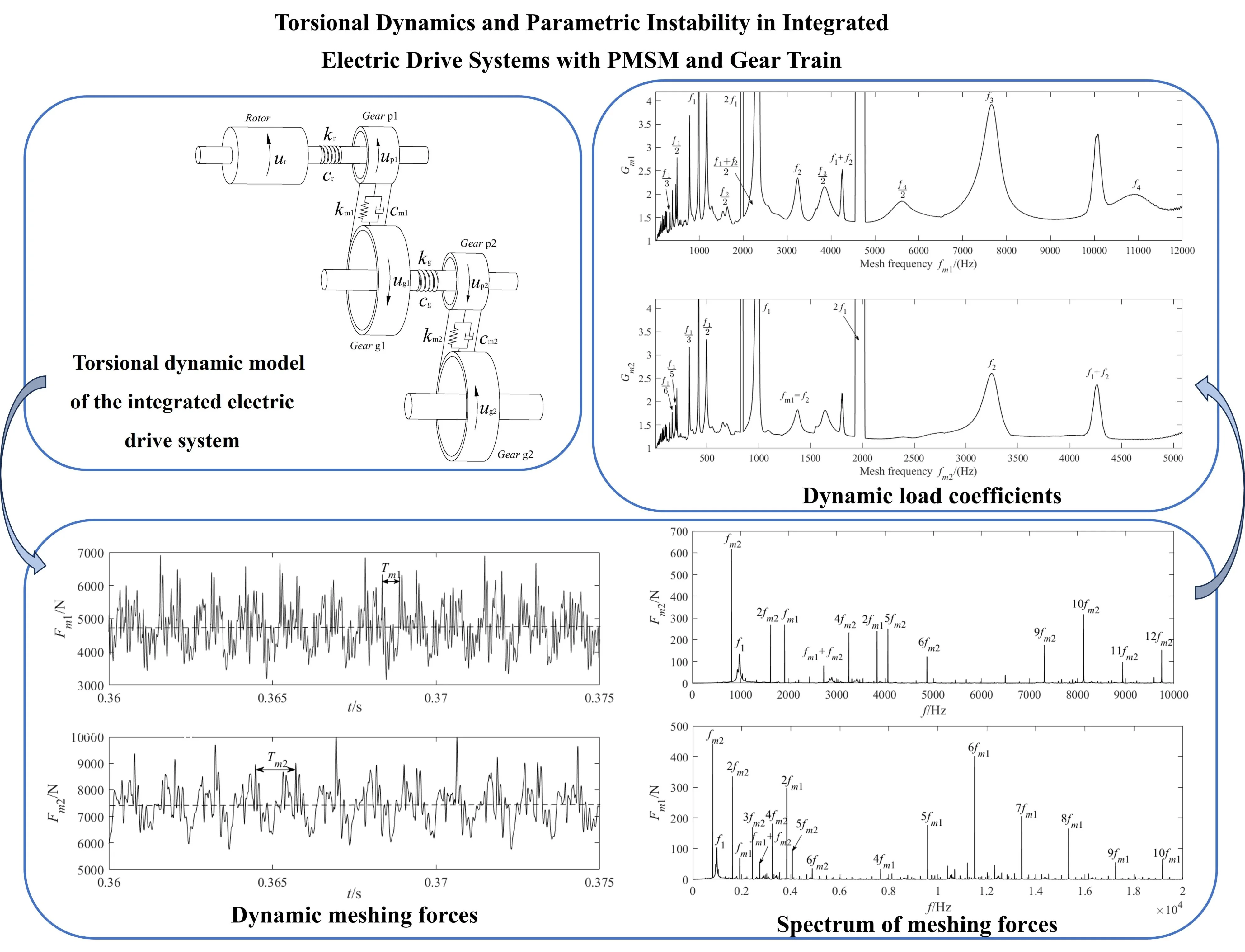
The dynamic model of the integrated electric drive system is composed of a motor module and a gear transmission system module, as illustrated in Fig. 1. Here, the components labeled , and represent the rotor of the permanent magnet synchronous motor, the driving gear, and driven gear, respectively. The synchronous motor operates at high speed, and after passing through the two-stage meshing gear pairs and , the driven gear delivers high torque and outputs at low speed.
Assuming that the stiffness of the bearing support is significantly greater than that of the gear pair, only torsional vibrations are considered. The torsional displacement of each component is defined as a generalized coordinate of the system:
In Fig. 1, and represent the torsional stiffness of the motor output shaft and the double gear shaft, respectively, while and represent the mesh stiffness of the two gear pairs. A corresponding convention applies to the damping coefficients, denoted as , , , and .
Fig. 1Torsional dynamic model of the integrated electric drive system
2.1. Electromagnetic excitation of the permanent magnet synchronous motors
2.1.1. Magnetomotive force of the stator
According to the principles of electrical engineering, when a three-phase symmetrical current is supplied, the symmetrical three-phase stator windings produce a resultant magnetomotive force (MMF) with a fundamental component as follows:
where, represents the fundamental amplitude of the magnetomotive force, is the current frequency, denotes the number of pole pairs of the motor, indicates the relative angle between the centerline of the motor stator yoke and the permanent magnet pole, is the number of series turns per phase winding, and is the effective value of the current. , where is the distribution coefficient of the fundamental winding, is the winding distribution coefficient, and is the winding pitch coefficient. The expressions for and are given as follows:
where, represents the number of slots per pole per phase, where is the number of stator slots and is the number of winding phases. Additionally, denotes the winding pitch, and represents the pole pitch.
2.1.2. Magnetomotive force of the rotor
Taking into account the torque angle resulting from load torque at the rotor, the fundamental magnetomotive force of the permanent magnet rotor when the motor operates under load can be expressed as:
where, denotes the fundamental amplitude of the permanent magnet magnetomotive force, refers to the remanent magnetic flux density of the permanent magnet material, represents the permeability of the permanent magnet, and are the pole arc coefficient and the magnetization direction thickness of the permanent magnet, respectively, is the torque angle of the rotor, and denotes the internal power factor angle.
2.1.3. Synthetic magnetomotive force
The expression for the fundamental synthetic magnetomotive force in the stator coordinate system is given as follows:
The air gap magnetic field energy of a permanent magnet synchronous motor can be expressed as:
where is the effective length of the rotor, is the average radius of the air gap, denotes the air gap permeance, is the vacuum permeability, represents the magnetic saturation coefficient, and is the length of the air gap.
By taking the derivative of Eq. (6), the electromagnetic torque of the rotor under load is obtained as:
Expanding the trigonometric function containing approximately, the electromagnetic torque can be expressed as:
where . Here, , , and are electromagnetic parameters determined by the motor's structural and operational conditions.
When only the first two components of the steady-state electromagnetic torque are considered, the expression simplifies to:
where, the coefficient has the same dimension as torsional stiffness and is therefore referred to as the electromagnetic torsional stiffness, denoted as .
2.2. Excitation of gear system parameters
During a single meshing period, the mesh stiffness differs significantly between the single-tooth and double-tooth engagement zones of a gear pair. This abrupt change in stiffness can induce the gear pair to generate noticeable vibration acceleration. In contrast, within either the single-tooth or double-tooth meshing zone, the variation in meshing stiffness is minimal, and this gradual change has a relatively minor influence on the vibration response [25].
Therefore, taking into account the meshing phase, the time-varying meshing stiffness of the gear pair can be expressed as a Fourier series in the following form:
The Fourier coefficients corresponding to Eq. (10) are given by:
where and are the fluctuation and mean components of the mesh stiffness, respectively, is the meshing frequency, denotes the meshing phase, and is the contact ratio of the gear pair.
The comprehensive error of gear pair is defined as follows:
where is the constant component of the gear pair error, represents the amplitude of the error variation, and denotes the initial phase of the error.
3. Equations of motion for the system
The vibration differential equation for the integrated electric drive system is derived as follows:
where, is the radius of the motor rotor shaft; and are the base circle radii of the driving and driven gears, respectively; and (where ) represents the rotational inertia of each component. The relative displacements of the gear pair are given by:
Substituting Eq. (14) into Eqs. (13) yields the matrix form of the system's differential equation:
where , , , and represent the generalized mass matrix, damping matrix, stiffness matrix, and generalized force vector, respectively. For further details, refer to the Appendix.
4. Decoupling of dynamic equations and stability analysis
Neglecting external excitations and damping, the equation for the system’s free vibration is:
where is the variable stiffness matrix, and is the average stiffness matrix. By setting in Eq. (16), the system equation simplifies to:
Solving Eq. (17) leads to the eigenvalue problem:
where and are the -th natural frequency and the corresponding mode vector, respectively. Let:
where is the main modal matrix, and is the generalized coordinate vector. Substituting Eq. (19) into Eq. (16) and left-multiplying by , the regular modal equation of the system is obtained:
Expanding Eq. (20) gives:
where , and the coefficient terms are expressed as:
Using the multi-scale method, time variables representing different scales are introduced:
where . The first-order approximation solution of Eq. (21) is assumed as:
Substituting Eq. (23) into Eq. (21), and equating terms of the same power of yields:
where is the complex amplitude, and denotes the complex conjugate of the preceding term.
Substitution Eq. (24) into Eq. (25) leads to:
From the analysis of the above equation, in addition to the resonance that occurs when the meshing frequency approaches the system’s natural frequency, secular terms arise when approaches the combination frequencies . This behavior indicates that the gear system exhibits an instability region due to parametric excitation.
5. Parameter excitation vibration characteristics
The key parameters for the PMSM module and the two-stage gear transmission module, corresponding to the model in Fig. 1, are provided in Table 1 and Table 2, respectively.
The natural frequencies of the integrated electric drive system, calculated from Eq. (17), are given in Table 3.
5.1. Dynamic characteristics of the meshing force
The differential Eq. (13) are solved numerically using the Runge-Kutta method, yielding real-time solutions for each degree of freedom in the system. The meshing force for gear pair is calculated as follows:
where and denote the time-varying meshing stiffness and damping coefficients, respectively.
Table 1Parameters of the motor module
Parameters | Values | Parameters | Values |
Number of phases | 3 | Number of series conductors per phase | 80 |
Pole pair number | 4 | Number of conductors per slot | 10 |
Number of slots | 48 | Axial length of stator core (mm) | 100 |
Winding pitch | 5 | Axial length of rotor core (mm) | 100 |
Polar distance | 6 | Remanent magnetic flux density (T) | 1.097 |
Rotor inner diameter (mm) | 70 | Thickness of permanent magnet (mm) | 5 |
Rotor outer diameter (mm) | 123.8 | Torsional stiffness (N·m /rad) | 2.1×10⁵ |
Stator inner diameter (mm) | 125 | Width of permanent magnet (mm) | 16 |
Table 2Parameters of the gear transmission
Parameters | Values |
Number of teeth | , , , |
Modulus (mm) | , |
Tooth width (mm) | , , , |
Pressure angle (°) | , |
Moment of inertia (kg·m2) | 1.03×10⁻⁴, 2.418×10⁻³ 7.3×10⁻⁴, 7.95×10⁻² |
Mesh stiffness (N/m) | 614.68×10⁶, 347.83×10⁶ 640.77×10⁶, 362.96×10⁶ |
Contact ratio | , |
Torsional stiffness (N·m/rad) | 9.0×10⁵ |
Table 3Natural frequencies of the integrated electric drive system
Order | ||||
Frequency (Hz) | 1001.15 | 3293.81 | 7868.40 | 11122.03 |
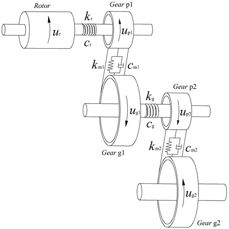
Under constant torque conditions and with the motor speed maintained at 5000 r/min, the variation of meshing force with time is illustrated in Fig. 2. The dynamic meshing force oscillates around the static meshing force value, represented by the dashed line. Furthermore, high-frequency fluctuations with small amplitudes are observed within each meshing cycle, which are caused by the time-varying stiffness parameters such as the contact ratio.
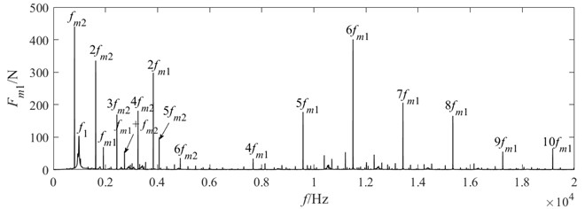
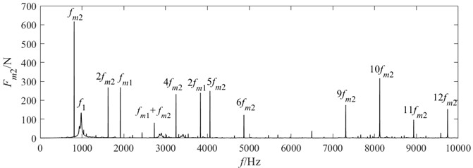
With the torque held constant and the motor speed maintained at 5000 r/min, the frequency spectrum of the meshing force is shown in Fig. 3. The results indicate that, in addition to the meshing frequency of the current gear pair, the meshing frequencies of the other gear stage, as well as the system’s natural frequencies, are also present in the spectrum of each meshing force. This suggests the occurrence of a coupled multi-frequency vibration phenomenon within the system.
In the frequency spectrum of the meshing force for the high-speed gear pair , not only does the low-speed meshing frequency (with relatively higher amplitude) appear, but the system’s natural frequency and the combined frequency are also present. Similarly, the high-speed stage meshing frequency also appears in the spectrum of the meshing force of the low-speed stage, though with smaller amplitudes. This frequency domain behavior reveals that the coupling effect between the meshing vibrations of different gear pairs is asymmetric.
This phenomenon occurs because the torsional internal force of the connecting shaft couples the vibration displacements of different frequencies together, which then act on the two connected components separately as force and reaction. The coupled components, in turn, feed back the vibration displacement containing new frequencies to the meshing force of the gear pair in the form of equivalent meshing line deformation. As a result, mutual coupling arises between the meshing forces of different gear pairs.
Fig. 2Dynamic meshing force of gear pair
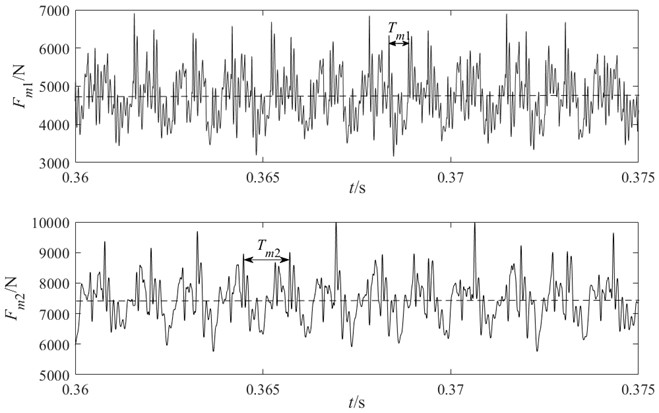
Fig. 3Spectrum of meshing forces
5.2. Characteristics of dynamic load coefficient
The dynamic characteristics of the gear system, particularly under high-speed operating conditions, have a direct impact on its overall performance. In this study, the dynamic load coefficient is used as an indicator to evaluate the dynamic behavior of the gear transmission system. The dynamic load coefficient is defined as:
where, denotes the dynamic meshing force, and represents the static meshing force.
The relationship between the dynamic load coefficient and the meshing frequency is shown in Fig. 4. It can be observed that, within the investigated frequency range, the dynamic load coefficient of gear pair is significantly higher than that of gear pair . This is attributed to the higher rotational speed and more pronounced vibration of gear pair . Furthermore, when the meshing frequency approaches the natural frequency of the system, both dynamic load coefficients and exhibit a sharp increase, which is caused by the strong primary resonance response of the system.
Fig. 4Dynamic load coefficients of the system
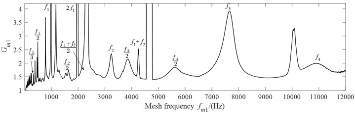
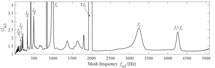
Owing to the time-varying meshing stiffness of the gears, parametric vibrations are excited. The meshing frequencies and induce subharmonic resonance, superharmonic resonance, and additive combination resonance responses in the system.
Specifically, when integer multiples of the meshing frequency (e.g., or ) approach the natural frequencies or , superharmonic resonance is observed, resulting in a distinct resonance peak. Similarly, subharmonic resonance occurs when or , which is accompanied by a broader resonance region in the vicinity.
When the meshing frequency or one of its harmonics approaches the sum of two natural frequencies, a pronounced additive combination resonance occurs, accompanied by a distinct peak in the dynamic load coefficient. Specifically, resonances at and are directly excited by the fundamental meshing frequency, whereas resonance at is driven by the second harmonic of the meshing frequency.
The time-varying meshing stiffness in multistage gear transmission systems induces parametric excitation and dynamic coupling between different gear pairs, leading to complex resonance phenomena. Effectively addressing these issues requires a systematic and multi-faceted approach focused on shifting critical resonance frequencies outside the operational range, reducing vibration amplitudes, or mitigating their dynamic impact.
By adjusting the stiffness or rotational inertia of relevant components – for example, by modifying the diameter of the intermediate shaft or optimizing the bearing span – the natural frequencies of the system can be effectively adjusted. In addition, through rational design of gear transmission ratios and operating speeds, it can be ensured that all meshing frequencies, along with their harmonics and subharmonics, avoid coincidence with the system’s natural frequencies or their combination frequencies.
The use of high-contact-ratio (HCR) gears contributes to reducing the fluctuation amplitude of mesh stiffness, thereby mitigating parametric excitation effects. Furthermore, increasing system damping can effectively suppress resonance peak amplitudes. The installation of torsional vibration isolators on intermediate shafts can decouple the transmission of vibrational energy along the drive train.
6. Conclusions
This study established a nonlinear torsional dynamic model for an integrated electric drive system comprising a PMSM and a two-stage gear train. Using the multi-scale method and numerical simulations, the parametric instability and vibration characteristics induced by time-varying mesh stiffness were thoroughly investigated. The principal conclusions are as follows:
1) In the time domain, the dynamic meshing force oscillates around the static meshing force value, accompanied by high-frequency, small-amplitude fluctuations.
2) The frequency spectrum of the meshing force contains not only the meshing frequency of the current gear pair, but also the natural frequencies of the system and the meshing frequencies of other gear pairs.
3) Within the frequency range studied, the dynamic load coefficient of high-speed gear pair is significantly greater than that of the low-speed gear pair .
4) The dynamic load coefficient of the gear pair peaks not only under the primary resonance conditions, but also during subharmonic, superharmonic, and combination resonance responses. In particular, when the meshing frequency approaches twice the first-order natural frequency, the instability regions induced by subharmonic resonance is significantly larger.
The analytical approach developed in this work can be extended and applied to more complex integrated electric drive systems than those considered here, such as systems incorporating permanent magnet synchronous motors coupled with planetary gear transmission mechanisms.
References
-
Y. Shen, S. Yang, and X. Liu, “Nonlinear dynamics of a spur gear pair with time-varying stiffness and backlash based on incremental harmonic balance method,” International Journal of Mechanical Sciences, Vol. 48, No. 11, pp. 1256–1263, Nov. 2006, https://doi.org/10.1016/j.ijmecsci.2006.06.003
-
M. T. Khabou, N. Bouchaala, F. Chaari, T. Fakhfakh, and M. Haddar, “Study of a spur gear dynamic behavior in transient regime,” Mechanical Systems and Signal Processing, Vol. 25, No. 8, pp. 3089–3101, Nov. 2011, https://doi.org/10.1016/j.ymssp.2011.04.018
-
S. Wei, Q. K. Han, X. J. Dong, Z. K. Peng, and F. L. Chu, “Dynamic response of a single-mesh gear system with periodic mesh stiffness and backlash nonlinearity under uncertainty,” Nonlinear Dynamics, Vol. 89, No. 1, pp. 49–60, Mar. 2017, https://doi.org/10.1007/s11071-017-3435-z
-
Q. Chen, Y. Wang, W. Tian, Y. Wu, and Y. Chen, “An improved nonlinear dynamic model of gear pair with tooth surface microscopic features,” Nonlinear Dynamics, Vol. 96, No. 2, pp. 1615–1634, Mar. 2019, https://doi.org/10.1007/s11071-019-04874-1
-
Z. Cao, Z. Chen, and H. Jiang, “Nonlinear dynamics of a spur gear pair with force-dependent mesh stiffness,” Nonlinear Dynamics, Vol. 99, No. 2, pp. 1227–1241, Nov. 2019, https://doi.org/10.1007/s11071-019-05348-0
-
Y.-H. Hu, Q.-G. Du, and S.-H. Xie, “Nonlinear dynamic modeling and analysis of spur gears considering uncertain interval shaft misalignment with multiple degrees of freedom,” Mechanical Systems and Signal Processing, Vol. 193, p. 110261, Jun. 2023, https://doi.org/10.1016/j.ymssp.2023.110261
-
J. Lin and R. G. Parker, “Mesh stiffness variation instabilities in two-stage gear systems,” Journal of Vibration and Acoustics, Vol. 124, No. 1, pp. 68–76, Jan. 2002, https://doi.org/10.1115/1.1424889
-
J. Lin and R. G. Parker, “Planetary gear parametric instability caused by mesh stiffness variation,” Journal of Sound and Vibration, Vol. 249, No. 1, pp. 129–145, Jan. 2002, https://doi.org/10.1006/jsvi.2001.3848
-
G. Liu and R. G. Parker, “Nonlinear dynamics of idler gear systems,” Nonlinear Dynamics, Vol. 53, No. 4, pp. 345–367, Dec. 2007, https://doi.org/10.1007/s11071-007-9317-z
-
Z. Rao, C. Y. Zhou, Z. H. Deng, and M. Y. Fu, “Nonlinear torsional instabilities in two-stage gear systems with flexible shafts,” International Journal of Mechanical Sciences, Vol. 82, pp. 60–66, May 2014, https://doi.org/10.1016/j.ijmecsci.2014.02.021
-
G. Liu, J. Hong, and R. G. Parker, “Influence of simultaneous time-varying bearing and tooth mesh stiffness fluctuations on spur gear pair vibration,” Nonlinear Dynamics, Vol. 97, No. 2, pp. 1403–1424, Jun. 2019, https://doi.org/10.1007/s11071-019-05056-9
-
S. H. Gawande and V. V. Palande, “Half width and phasing method for reduction of instabilities of mesh stiffness variation in two-stage gear,” Australian Journal of Mechanical Engineering, Vol. 21, No. 3, pp. 815–829, May 2023, https://doi.org/10.1080/14484846.2021.1914889
-
S. H. Gawande and V. V. Palande, “Reducing instabilities of mesh stiffness variation in two-stage gear using phasing method,” JMST Advances, Vol. 2, No. 4, pp. 89–101, Sep. 2020, https://doi.org/10.1007/s42791-020-00035-3
-
A. Beinstingel, R. G. Parker, and S. Marburg, “Experimental measurement and numerical computation of parametric instabilities in a planetary gearbox,” Journal of Sound and Vibration, Vol. 536, p. 117160, Oct. 2022, https://doi.org/10.1016/j.jsv.2022.117160
-
X. Chen, S. Yuan, and Z. Peng, “Nonlinear vibration for PMSM used in HEV considering mechanical and magnetic coupling effects,” Nonlinear Dynamics, Vol. 80, No. 1-2, pp. 541–552, Jan. 2015, https://doi.org/10.1007/s11071-014-1887-y
-
H.-J. Shin, J.-Y. Choi, H.-I. Park, and S.-M. Jang, “Vibration analysis and measurements through prediction of electromagnetic vibration sources of permanent magnet synchronous motor based on analytical magnetic field calculations,” IEEE Transactions on Magnetics, Vol. 48, No. 11, pp. 4216–4219, Nov. 2012, https://doi.org/10.1109/tmag.2012.2200658
-
H. Liu, Y. Wu, X. Wang, P. Yan, and X. Zhang, “Nonlinear normal modes and primary resonance for permanent magnet synchronous motors with a nonlinear restoring force and an unbalanced magnetic pull,” Nonlinear Dynamics, Vol. 97, No. 2, pp. 1197–1213, Jun. 2019, https://doi.org/10.1007/s11071-019-05040-3
-
Z. Yang, S. Wang, J. Hong, and J. Li, “Analysis of electromagnetic exciting force and vibration of rotating armature permanent magnet synchronous motor,” The Journal of Engineering, Vol. 2018, No. 17, pp. 1903–1908, Oct. 2018, https://doi.org/10.1049/joe.2018.8345
-
Z. Wu, S. Zuo, Z. Huang, X. Hu, S. Chen, and C. Liu, “Modelling, calculation and analysis of electromagnetic force and vibroacoustic behavior of integer-slot permanent magnet synchronous motor considering current harmonics,” Journal of Vibration Engineering and Technologies, Vol. 10, No. 3, pp. 1135–1152, Feb. 2022, https://doi.org/10.1007/s42417-022-00434-x
-
L. Sheng, W. Li, G. Xin, Y. Wang, M. Fan, and X. Yang, “Nonlinear torsional vibration analysis and nonlinear feedback control of complex permanent magnet semidirect drive cutting system in coal cutters,” Complexity, Vol. 2019, No. 1, May 2019, https://doi.org/10.1155/2019/9359218
-
L. Sheng, W. Li, S. Jiang, J. Chen, and A. Liu, “Nonlinear torsional vibration analysis of motor rotor system in shearer semi-direct drive cutting unit under electromagnetic and load excitation,” Nonlinear Dynamics, Vol. 96, No. 2, pp. 1677–1691, Mar. 2019, https://doi.org/10.1007/s11071-019-04878-x
-
J. Hu, T. Peng, M. Jia, Y. Yang, and Y. Guan, “Study on electromechanical coupling characteristics of an integrated electric drive system for electric vehicle,” IEEE Access, Vol. 7, pp. 166493–166508, Jan. 2019, https://doi.org/10.1109/access.2019.2953310
-
Y. Yi, D. Qin, and C. Liu, “Investigation of electromechanical coupling vibration characteristics of an electric drive multistage gear system,” Mechanism and Machine Theory, Vol. 121, pp. 446–459, Mar. 2018, https://doi.org/10.1016/j.mechmachtheory.2017.11.011
-
K. Liu, W. Wu, S. Yuan, G. Lu, and X. Chen, “Modal characteristics of electric vehicle powertrain considering electromagnetic effect,” Journal of Sound and Vibration, Vol. 530, p. 116972, Jul. 2022, https://doi.org/10.1016/j.jsv.2022.116972
-
D. Zhang, R. Zhu, M. Li, W. Tan, and P. Li, “Meshing stiffness parametric vibration of coaxial contrarotating encased differential gear train,” Mathematical Problems in Engineering, Vol. 2021, pp. 1–13, Feb. 2021, https://doi.org/10.1155/2021/8950945
About this article

This work was financially supported by the National Key Laboratory of Science and Technology on Helicopter Transmission (Grant No. HTL-O-21G09), Natural Science Research Project of Jiangsu Province Colleges and Universities (Grant No. 22KJA460012), 2023 Jiangsu Outstanding Scientific and Technological Innovation Team in Colleges and Universities (Robotic Micro-Servo Control Technology and Applications).
The datasets generated during and/or analyzed during the current study are available from the corresponding author on reasonable request.
Donglin Zhang: conceptualization, methodology, software, writing-original draft, project administration, funding acquisition. Rupeng Zhu: visualization, supervision. Luqiang Ma: software, writing-original draft.
The authors declare that they have no conflict of interest.
