Abstract
This paper addresses the static strength assessment of bogie frames for PE2 (M, U) series industrial traction units used in the mining industry. Currently, a significant portion of the widely operated PE2M and PE2U traction units has been in service for 40-50 years. Given that the manufacturer-specified service life for these units is 24 years, there is a critical need to justify the feasibility of extending their operation to more than double their original design life. The objective of this research is to determine the mean stress of the bogie frame loading cycle. A 3D model of the bogie frame was developed using SolidWorks, and structural analysis was performed via the Finite Element Method (FEM) in Ansys Mechanical. The finite element analysis results indicated a mean Von Mises stress of 63 MPa, and a safety factor of 2.65. Based on the findings, relatively higher stresses were observed in the zones beneath the central pivot plate of the pivot transom. The low values of mean stress, combined with the biaxiality levels, confirm that the bogie frame possesses sufficient static strength. These research findings can be utilized to evaluate the fatigue strength and residual life of the bogie frame, as well as to justify its service life extension.
1. Introduction
Currently, industrial traction units such as the PE2M, PE2U, and MPE2U series, developed based on the PE2 traction unit platform, are extensively utilized for mineral transportation in major enterprises of the Republic of Uzbekistan, including “Uzbekcoal” JSC and “Almalyk Mining and Metallurgical Combine” JSC (AMMC) [1]-[4].
The production history of these units reveals a systematic evolution: between 1967 and 1970, twenty experimental units of the PE2 series were manufactured at the “Dnepropetrovsk Electric Locomotive Building Plant” (equipped with NB-406D traction motors). Subsequently, from 1970 to 1985, 705 modernized PE2M units (equipped with DT-9N motors) were produced. This was followed by the manufacturing of 174 upgraded PE2U units between 1985 and 2019, featuring NB-511 traction motors [6].
In response to the development of the new “Yoshlik-1” mine, the MPE2U traction units were manufactured at the “Tbilisi Electric Locomotive Building Plant” between 2019 and 2021 by order of “AMMC” JSC. Compared to the PE2U series, these newer units are distinguished by their advanced electrical equipment, on-board computers, video surveillance systems, and enhanced modular driver cabins equipped with air conditioning systems [6].
A significant portion of the current traction unit fleet consists of PE2M and PE2U series manufactured between 1970 and 1990, most of which have already exceeded their designated service life [4], [5]. During the interim period until the fleet is fully modernized, it is imperative to extend the operational life of existing units by evaluating their residual resource. The primary criterion for extending the service life of locomotives is the structural integrity assessment of their load-bearing frame structures [7]-[10]. One of the key indicators of structural integrity for these frames is their static strength [11]-[13].
In contemporary engineering practice, numerous Computer-Aided Engineering (CAE) software packages based on the FEM are available for performing structural analyses. These tools are recognized as high-precision digital modeling instruments widely integrated into modern engineering workflows [14]. Specifically, the Ansys software suite covers a comprehensive spectrum of modern engineering analyses, offering capabilities for almost every type of structural simulation [15], [16].
FEM is a globally recognized numerical computation method in locomotive engineering. When boundary conditions and loads are correctly applied, the margin of error for complex structures and loading scenarios typically does not exceed 10 % [17]-[19]. According to the requirements of European standards EN 12663-1 and EN 13749, the use of FEM is strictly mandated for the strength analysis of complex load-bearing locomotive frame structures. Consequently, FEM is actively employed by the global scientific community [20]-[28] to conduct structural analyses of bogie frames in modern railway transport engineering.
2. Materials and methods
2.1. Technical description of the bogie frame
The PE2 series traction units consist of a control electric locomotive (EL) and two motor dump cars (MD), forming a three-section industrial electric locomotive configuration (EL+2MD) designed to generate the necessary traction for ore transportation in the mining industry. Each section – the control locomotive and the motor dump cars – is supported by two two-axle bogies through one central and two side bearings per bogie. A key feature of this design is the interchangeability of the bogies between the control locomotive and the motor dump cars. Furthermore, these bogies are unified across various series, including PE2, PE1, OPE2, OPE1A, OPE1B, and PE3T traction units, utilizing a pedestal-less (jawless) design with asymmetrically arranged traction motors [6].
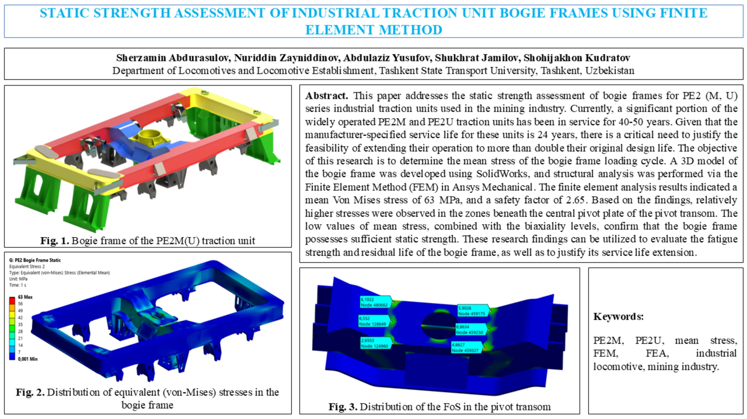
The bogie frame (Fig. 2) is engineered to distribute vertical loads among individual wheelsets via the suspension system, as well as to absorb and transmit traction, braking, and lateral forces from the wheelsets to the vehicle body frame. The bogie frame is a welded structure fabricated from steel plates, consisting of two side frames, a pivot transom, and front and rear end beams. The primary load-bearing elements of the frame feature a box-section geometry. The side frames and end beams are welded from four rolled steel plates, while the pivot transom is constructed from five plates (three vertical and two horizontal). Support brackets are welded to the front and rear beams to facilitate the mounting of the bogie’s safety beams.
Fig. 1Bogie frame of the PE2M(U) traction unit
2.2. Materials and fabrication
All welded elements of the bogie frame are fabricated from 16D grade steel. The cast components of the frame, including the center pivot heel (pivot plate) and its housing, are manufactured from 20L-III cast steel, which has a carbon content of up to 0.22 %. To ensure structural stability and eliminate residual stresses induced during the welding process, the entire frame underwent a post-weld heat treatment (annealing) process.
The mechanical properties of the materials employed in the bogie frame structures are detailed in Table 1. The frame incorporates both rolled steel plates (16D) of varying thicknesses and cast steel components (20L).
Table 1Mechanical properties of the bogie frame materials
Material | Yield strength [MPa] | Endurance limit [MPa] | Young’s modulus [GPa] | Poisson’s Ratio |
16D | 235 | 170 | 210 | 0.3 |
20L | 216 | 165 | 175 |
2.3. Numerical simulation and load modeling
The structural strength of the bogie frame is evaluated in accordance with the regulatory framework of GOST 34939-2023. Under these requirements, stresses arising from constantly acting vertical static loads are defined as the mean stress of the loading cycle. The evaluated load case models the maximum operational regime (fully loaded unit handling track curves and irregular joints), which serves as a representative and conservative scenario for mining services characterized by heavy payload shifts and dynamic impacts.
The total weight force acting on the frame is distributed among the body supports: central support receives 50 % (), and side supports receive 25 % each (). A 3D solid model was developed in SolidWorks and analyzed within Ansys Mechanical. The finite element mesh consists of 271,404 elements and 877,275 nodes, utilizing high-order 3D solid 10-node tetrahedral elements to ensure accuracy. The global mesh size was set to 20 mm, with local mesh refinement down to 5 mm implemented at critical geometric transitions and fillets near the central pivot transom. A mesh convergence sensitivity analysis showed that refining the local element size from 10 mm to 5 mm induced less than a 3.2 % change in peak Von Mises stresses, confirming numerical model stability. Boundary conditions involve rigid constraints applied at the axle box jaw guides to simulate realistic wheelset-rail interaction, while vertical and horizontal tractive forces were applied as static equivalents on the central pivot plate.
3. Results and discussion
The FEA performed in Ansys Mechanical provided comprehensive data on the structural behavior of the PE2 bogie frame under static loading conditions. The simulation focused on equivalent stresses, and the structural safety factor, particularly in critical zones.
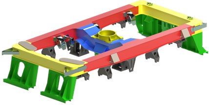
The distribution of equivalent von-Mises stresses across the bogie frame is illustrated in Fig. 2. The contour plot reveals that most of the frame structure experiences stress levels well below the material’s yield strength, indicated by the dominant blue zones (0-7 MPa).
Significant stress concentrations are localized in the pivot transom, specifically underneath the central pivot plate due to the combined multi-axial gradients of vertical weight and horizontal tractive pivoting. The maximum equivalent stress recorded is 63 MPa, forming near structural discontinuities at the pivot connection. According to GOST 34939-2023, this peak static value serves as the mean stress for the fatigue cycle baseline. Given that the structural steel possesses a yield strength of 216-235 MPa, this stress level leaves a substantial elastic margin, ensuring that the critical frame components operate safely away from plastic deformation limits.
A detailed investigation into the structural integrity reserve was conducted for the most heavily loaded component – the pivot transom. Fig. 3 presents the Factor of Safety (FoS) contour for this specific region, calculated relative to the material’s yield limit.
The analysis identifies specific nodes with minimum safety factors due to local stress fields: the lowest Factor of Safety (FoS) recorded is 2.65 at Node 124960, while adjacent geometric transitions exhibit factors from 4.88 to 6.86 (e.g., Node 459327 and Node 459250). These reserves comply with standard railway design criteria (FoS > 2.0).
Fig. 2Distribution of equivalent (von-Mises) stresses in the bogie frame
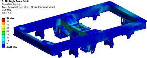
Fig. 3Distribution of the FoS in the pivot transom
It must be emphasized that while static FEM analysis yields a satisfactory safety margin of 2.65, it does not directly calculate residual life, which is governed by fatigue endurance thresholds and dynamic load spectra. However, this static baseline establishes a direct prerequisite for service life extension by identifying high-stress core zones where future fatigue cracks are most likely to initiate, thereby guiding targeted non-destructive testing and subsequent cyclic life damage models under dynamic mining environments.
4. Conclusions
This study performed a comprehensive structural assessment of the industrial traction unit bogie frame through FEA, adhering to the regulatory requirements of GOST 34939-2023. Based on the numerical simulations and stress distribution analysis, the following conclusions were drawn:
Static Structural Integrity: The FEA confirms high structural rigidity under static design loads. The maximum Von Mises stress of 63 MPa is well within elastic boundaries, eliminating risks of premature macro-yielding.
Critical Zone Identification: The pivot transom experiences local stress concentrations near geometric transitions under the central support. The minimum safety factor of 2.65 satisfies standard engineering codes (FoS > 2.0).
Fatigue Baseline Link: The calculated static baseline of 63 MPa defines the mean stress of the loading cycle. While static evaluation alone cannot establish residual life, it critically uncovers the crack initiation hot-spots required for subsequent fatigue life modeling and life extension authorization under GOST 34939-2023.
Methodological Setup: The numerical model setup (271,404 high-order elements, 5 mm local refinement, 3.2 % convergence limit) provides a stable and verified framework for rolling stock structural monitoring.
In summary, the investigated bogie frame design meets all contemporary safety and strength criteria for industrial traction units, ensuring reliable performance in demanding mining and transport environments. Furthermore, the identified stress distribution and substantial safety margins provide a technical justification for extending the operational service life of these load-bearing structures beyond their design limits. The results suggest that through systematic structural monitoring and targeted reinforcement of the identified critical zones, the longevity and economic efficiency of the traction units can be significantly enhanced.
References
-
S. Abdurasulov, N. Zayniddinov, O. Khamidov, A. Yusufov, and S. Jamilov, “Stress-strain state analysis of cross beam of main frame of industrial electric locomotives PE2M and PE2U,” in AIP Conference Proceedings, Vol. 3317, No. 1, p. 060011, Jan. 2025, https://doi.org/10.1063/5.0266927
-
S. Abdurasulov, S. Utkir, J. Nikolay, O. Ablyalimov, and T. You, “Strength analysis of the central support structure of the PE2M(U) industrial traction unit using finite element method,” Vibroengineering Procedia, Vol. 60, pp. 697–703, 2025, https://doi.org/10.21595/vp.2025.25602
-
S. Abdurasulov, N. Zayniddinov, A. Yusufov, S. Jamilov, K. Kosimov, and T. You, “Evaluation of mean stress under load cycle of PE2M(U) industrial traction unit motorized dumpcar underframe using finite element method,” Vibroengineering Procedia, Vol. 60, pp. 731–737, 2025, https://doi.org/10.21595/vp.2025.25670
-
S. Abdurasulov et al., “Determination of mechanical properties of the material of load-bearing structures of the traction unit with expired warranty lifetime,” in Proceedings of the 6th International Conference on Construction Mechanics, Hydraulics and Water Resources Engineering Autumn Season, Vol. 1, pp. 65–74, 2024, https://doi.org/10.5220/0013452300004644
-
D. Bannikov, A. Radkevich, and A. Muntian, “Modernization of the buffer beam of PE2U traction unit electric locomotive,” IOP Conference Series: Materials Science and Engineering, Vol. 985, No. 1, p. 012035, Nov. 2020, https://doi.org/10.1088/1757-899x/985/1/012035
-
S. Abdurasulov, N. Zayniddinov, A. Yusufov, S. Jamilov, and F. Khikmatov, “Characteristics of industrial traction units and their load-bearing structures,” (in Russian), Transport Bulletin – Transport Newsletter, Vol. 1, No. 4, pp. 45–53, 2024, https://doi.org/10.56143/2181-2438-2024-4-45-53
-
O. Khamidov, A. Yusufov, S. Jamilov, and S. Kudratov, “Remaining life of main frame and extension of service life of shunting locomotives on railways of Republic of Uzbekistan,” E3S Web of Conferences, Vol. 365, p. 05008, Jan. 2023, https://doi.org/10.1051/e3sconf/202336505008
-
A. V. Grishchenko, A. M. Yusufov, and D. N. Kurilkin, “Forecasting the residual service life of the main frame and extending the service life of shunting locomotives JSC “UTY,” (in Russian), E3S Web of Conferences, Vol. 460, p. 06032, 2023, https://doi.org/10.1051/e3sconf/202346006032
-
I. Raxmiddinov, S. Fayzibaev, Y. Abdulaziz, Y. Taiwen, K. Kosimov, and N. Abdullayev, “Experimental and finite element analysis of the structural durability of special self-propelled rolling stock frames,” Vibroengineering Procedia, Vol. 60, pp. 186–192, Dec. 2025, https://doi.org/10.21595/vp.2025.25624
-
A. Yusufov, K. Kosimov, and S. Kudratov, “Experimental evaluation of residual deflection and structural stiffness of the UzTE16M locomotive frame under static loading conditions,” Vibroengineering Procedia, Vol. 60, pp. 579–585, Dec. 2025, https://doi.org/10.21595/vp.2025.25369
-
V. S. Kossov, G. M. Volokhov, M. N. Ovechnikov, E. S. Oganyan, and A. A. Lunin, “Methods to justify the strength and life time of railway transport objects,” International Journal of Civil Engineering and Technology, Vol. 9, No. 13, pp. 1098–1104, 2018.
-
O. M. Bondarev, V. L. Gorobets, and S. V. Myamlin, “Methods and research concerning service life extension of suporting structures of traction rolling stock for industrial transport,” (in Ukrainian), Science and Transport Progress, No. 2(50), pp. 130–151, Apr. 2014, https://doi.org/10.15802/stp2014/23790
-
O. M. Bondaryev, V. L. Gorobets’, Y. M. Dzichkovs’Kyy, O. Y. Kryvchykov, D. O. Yagoda, and V. S. Bondaryeva, “Estimation of strength indices of parts of supporting structures of traction assemblies OPE1A and prolongation of their service life,” (in Ukrainian), Science and Transport Progress, No. 40, pp. 17–27, Apr. 2012, https://doi.org/10.15802/stp2012/6919
-
Y. Abdulaziz, K. Otabek, Z. Nuriddin, J. Shukhrat, and A. Sherzamin, “Application of computer-aided design (CAD) systems when solving engineering survey tasks,” Universum: Technical Sciences, No. 3-5 (108), pp. 5–9, 2023.
-
X. Chen and Y. Liu, Finite element modeling and simulation with ANSYS Workbench. Boca Raton, FL: CRC Press, 2014, https://doi.org/10.1201/b17284
-
M. K. Thompson and J. M. Thompson, ANSYS Mechanical APDL for finite element analysis. Oxford, UK: Butterworth-Heinemann, 2017.
-
Y. Gür and G. Cen, “Comparison of finite element analysis results with strain gauge measurements of a front axle housing,” Mechanical Sciences, Vol. 15, No. 1, pp. 257–268, Apr. 2024, https://doi.org/10.5194/ms-15-257-2024
-
R. Sulwinski and R. Johnston, “Methodology for validation of finite element analysis utilizing strain gauge measurements,” in ASME 2023 Verification, Validation, and Uncertainty Quantification Symposium, Vol. 86748, p. V001T03A002, 2023, https://doi.org/10.1115/vvuq2023-108749
-
S. E. E. Shahri, M. Lakhi, and S. Ranjbar, “Measurement of local strain: machine vision and finite element method,” Journal of Mechanical Science and Technology, Vol. 35, No. 3, pp. 979–985, Feb. 2021, https://doi.org/10.1007/s12206-021-0211-2
-
J.-W. Seo, S.-J. Kwon, C.-W. Lee, D.-H. Lee, and B.-C. Goo, “Fatigue strength and residual stress evaluation of repair welding of bogie frame for railway vehicles,” Engineering Failure Analysis, Vol. 119, p. 104980, Jan. 2021, https://doi.org/10.1016/j.engfailanal.2020.104980
-
M. Kassner, “Fatigue strength analysis of a welded railway vehicle structure by different methods,” International Journal of Fatigue, Vol. 34, No. 1, pp. 103–111, Jan. 2012, https://doi.org/10.1016/j.ijfatigue.2011.01.020
-
R. Xiu, M. Spiryagin, Q. Wu, S. Yang, and Y. Liu, “Fatigue life assessment methods for railway vehicle bogie frames,” Engineering Failure Analysis, Vol. 116, p. 104725, Oct. 2020, https://doi.org/10.1016/j.engfailanal.2020.104725
-
D. Chen, Q. Xiao, M. Mou, W. Yang, X. Liu, and Y. Zeng, “Fatigue reliability evaluation of heavy-haul locomotive car body underframe based on measured strain and virtual strain,” International Journal of Fatigue, Vol. 172, p. 107661, Jul. 2023, https://doi.org/10.1016/j.ijfatigue.2023.107661
-
F. Guo, S. Wu, J. Liu, X. Wu, and W. Zhang, “An innovative stepwise time-domain fatigue methodology to integrate damage tolerance into system dynamics,” Vehicle System Dynamics, Vol. 61, No. 2, pp. 550–572, Feb. 2023, https://doi.org/10.1080/00423114.2022.2051567
-
O. Koshel, S. Sapronova, and S. Kara, “Revealing patterns in the stressed-strained state of load-bearing structures in special rolling stock to further improve them,” Eastern-European Journal of Enterprise Technologies, Vol. 4, No. 7 (124), pp. 30–42, Aug. 2023, https://doi.org/10.15587/1729-4061.2023.285894
-
A. Yusufov, O. Khamidov, N. Zayniddinov, and S. Abdurasulov, “Prediction of the stress-strain state of the bogie frames of shunting locomotives using the finite element method,” E3S Web of Conferences, Vol. 401, p. 03041, 2023, https://doi.org/10.1051/e3sconf/202340103041
-
Y. Ruzmetov, N. Adilov, and S. Sultonov, “Strength assessment of the body of a weight checking wagon type 640-VPV,” E3S Web of Conferences, Vol. 264, p. 05021, Jun. 2021, https://doi.org/10.1051/e3sconf/202126405021
-
Z. Mukhamedova et al., “Calculating the fatigue strength of load-bearing structures of special self-propelled rolling stock,” Scientific Reports, Vol. 14, No. 1, p. 19205, Aug. 2024, https://doi.org/10.1038/s41598-024-70169-0
About this article

The authors have not disclosed any funding.
The datasets generated during and/or analyzed during the current study are available from the corresponding author on reasonable request.
The authors declare that they have no conflict of interest.

