Abstract
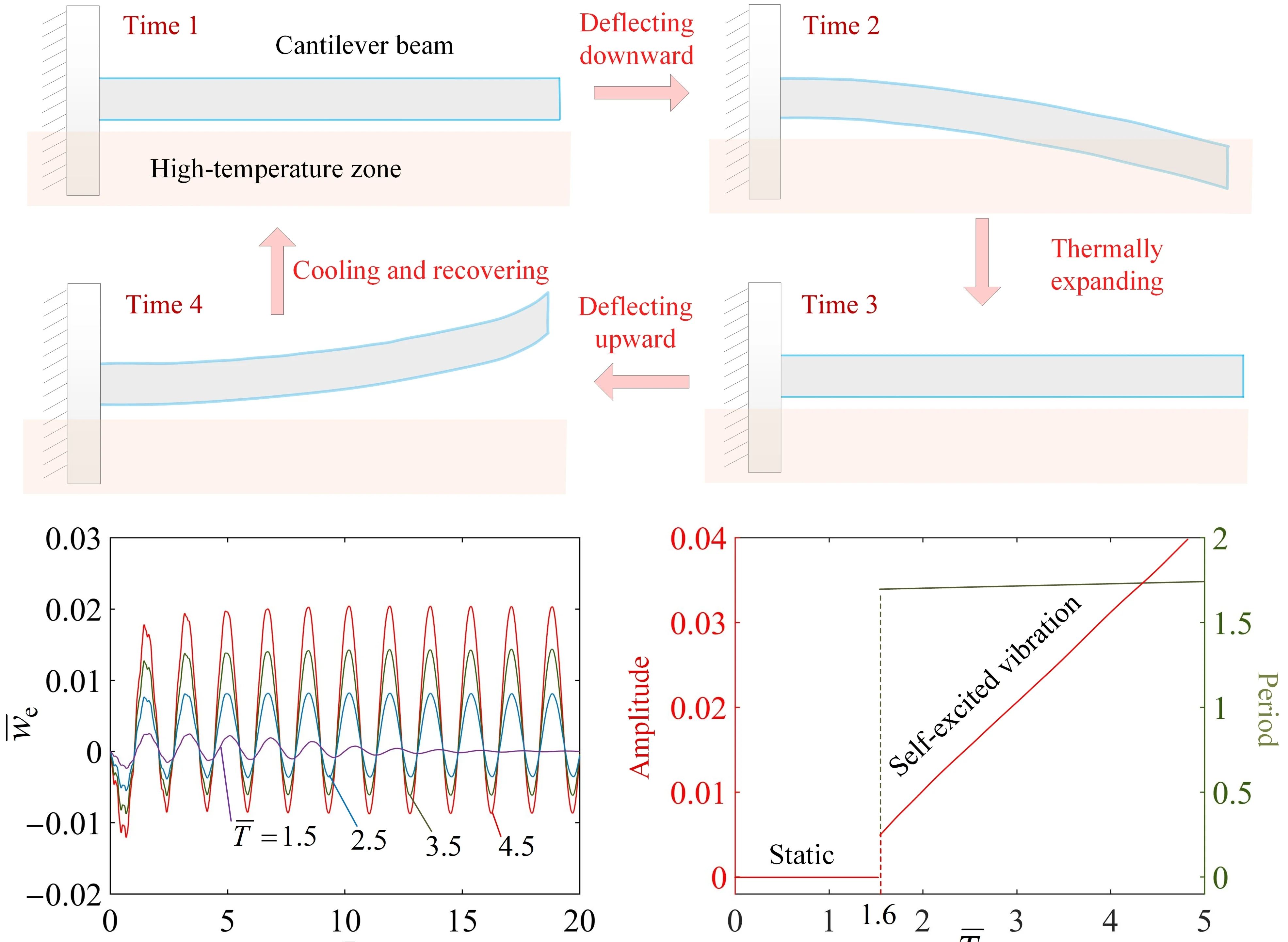
Responsive polymers can generate various self-sustained motions through the tuning of their geometric configurations, external stimuli, and boundary constraints. Research and innovation of novel self-sustained motions can broaden the scope of application for self-sustained active machines. In this paper, a novel dynamic model for the self-excited vibration of a thermally expandable cantilever beam driven by a steady temperature difference is constructed. The governing equation for the self-excited vibration of the beam is derived and solved using the modal superposition method. Numerical calculations reveal that the beam has two typical motion states, namely, the static state and the self-excited vibration state. The self-excitation mechanism is explained by the coupling between beam motion and the periodic switching of the thermally induced bending torque. The effects of each system parameter on the amplitude of the vibration in steady state are further investigated quantitatively, and the critical values for triggering the beam self-excited vibration are identified. Furthermore, the period of the self-excited vibration in steady state is almost unaffected by environmental parameters. The self-excited vibration cantilever beam holds promising potential for applications in soft robotics, energy harvesting, active motors, and self-sustained machinery.
Highlights
- A novel thermally expandable cantilever beam driven by a steady temperature difference is proposed.
- Two motion states namely the static state and the self-excited vibration state are presented.
- The beam can transition from the static state to the self-excited vibration state.
- The switching of the motion states can be designed by system parameters.
1. Introduction
Self-excited oscillation is a type of periodic non-equilibrium motion sustained by constant external stimuli [1-4], which can directly harvest energy from a steady environment to compensate for damping dissipation without complex control systems or external power supplies [5-7]. It exhibits unique advantages in active machines [8, 9], soft robotics [10-14], and energy harvesters [15-17]. Unlike traditional forced vibration, a self-excited system achieves continuous energy input and compensation through internal nonlinear coupling, and provides significant advantages in motion stability, structural simplicity, and environmental adaptability [18-20]. In recent years, the rapid development of various stimulus-responsive materials has provided abundant options for the design and realization of self-excited motion [21-27]. Exploring novel self-excited modes, revealing their dynamic mechanisms, and achieving controllable regulation have become important research directions in intelligent materials and structural mechanics [28-33].
Thermal energy, as a widely available and easily accessible clean energy source, has shown great potential in driving intelligent material systems [34-37]. Different from light [38-41], electrical [42-47], or magnetic stimuli [48-51], thermal energy can be stably obtained from temperature differences in the surrounding environment, with the advantages of wide distribution, strong penetration, and no requirement for special transmission media [52-54]. By exploiting the thermal expansion or thermal deformation characteristics of materials, structures can directly convert thermal energy into mechanical energy, which is especially suitable for operation in closed, high-temperature, or non-illuminated harsh environments [55-57]. The rational utilization of thermal energy provides a reliable and sustainable driving approach for realizing stable and controllable self-sustained motion of flexible structures [58-60].
Thermally responsive polymers are ideal materials for constructing self-excited driving systems owing to their reversible thermal deformation, simple actuation mode, and strong environmental compatibility [59-62]. By adjusting the thermal expansion properties, geometric configurations, and boundary constraints of materials, thermally responsive structures can generate self-oscillation [34], self-swimming [35], self-rolling [63], self-eversion/inversion [64], self-rolling back [65], self-swing [66], and other self-sustained motions under a constant temperature field to meet the driving requirements in different scenarios [57-59]. Among various structural forms, the cantilever beam has become an ideal platform for research due to its simple configuration, clear mechanical behavior, and easy integration [67,68]. However, the dynamic behavior of thermally expandable cantilever beams under a steady temperature difference, particularly the underlying self-excitation mechanism induced by the coupling between beam motion and thermally induced bending torque, remains insufficiently understood. Moreover, systematic investigations into the parameter-dependent regulation of such self-sustained oscillations are still lacking, limiting the development of thermally driven autonomous systems.
Motivated by these limitations, we propose a novel thermally expandable cantilever beam driven by a steady temperature difference in this study. Unlike conventional thermally driven oscillators that rely on external periodic heating or intrinsic material transitions, the proposed system achieves self-sustained vibration through the coupling between beam motion and position-dependent switching of the thermally induced bending torque. The governing equation for the self-excited vibration of the beam is derived and solved using the modal superposition method [69]. Two typical vibration states of the beam are investigated, and the mechanism of the self-excited vibration is theoretically explained. Furthermore, the effects of temperature difference, thermal expansion coefficient, and damping on the self-excited vibration characteristics are quantitatively studied. The proposed model provides a dynamic framework for understanding the self-excitation mechanism of the thermally expandable cantilever beam, in which the beam motion induces the switching of the thermally induced bending torque during the transition between temperature zones. This mechanism enables the conversion of a constant thermal input into sustained oscillations, offering new insights into the design of thermally driven self-excited structures.
2. Model and formulation
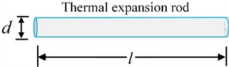
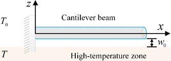
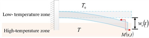
Fig. 1 sketches a self-excited vibration model of a thermally expandable cantilever beam driven by a steady temperature difference. The diameter and length of the thermal expansion rod in the stress-free state are and , respectively, as shown in Fig. 1(a). One end of the unheated thermal expansion rod is fixed, and a stabilized temperature field is applied at the bottom of the beam. In the initial state, the cantilever beam is straight, and the distance between the lower surface of the beam and the high-temperature zone is denoted as , as depicted in Fig. 1(b). The temperature field is simplified into spatially distributed high-temperature and low-temperature zones. This simplified temperature field configuration is widely adopted in theoretical studies of thermally driven self-sustained motion [35, 55, 65]. The temperatures in the high-temperature and low-temperature zones are set as and , respectively. At the beginning, the thermally expandable cantilever beam bends downward under its own gravity. Once the beam enters the high-temperature zone, a thermally induced bending torque is generated due to the inhomogeneous thermal expansion within the beam's cross-section, which causes the beam to move upward, as illustrated in Fig. 1(c). As a result, the thermally expandable cantilever beam can achieve self-sustained vibration driven by the steady temperature difference.
Fig. 1Self-excited vibration model of a thermally expandable cantilever beam driven by a steady temperature difference. The coupling between beam motion and the periodic switching of the thermally induced bending torque leads to self-excited vibration
a) Reference state
b) Initial state
c) Current state
The deflection of the beam is measured starting from the unbent state, and upward is defined as positive. The Cartesian coordinate system established in this paper is shown in Fig. 1(b). To facilitate analysis, we assume that the beam can be modeled as a classical cantilever beam under plane strain conditions. A linear viscous damping term is introduced to represent the energy dissipation of the beam, which is commonly adopted in vibration analysis of slender structures [9, 20, 27]. Therefore, the governing equation for the self-excited vibration of the cantilever beam can be given as:
where with mass density of the thermal expansion rod , denotes the damping coefficient, denotes the bending stiffness of the cantilever beam with Poisson’s ratio and Young’s modulus . represents the thermally induced bending torque, which is independent of , thus we can obtain .
While the beam is in the high-temperature zone, a thermally induced driving torque is generated due to the inhomogeneous thermal expansion within the beam's cross-section. When the length in the high-temperature zone is small relative to the total beam length, the cumulative effect of the thermally induced moment along the beam can be equivalently represented as a concentrated torque at the endpoint. Therefore, the influence of the length in the high-temperature zone on the driving torque is ignored. This simplification avoids the complex nonlinearities introduced by an integral-type distributed moment, facilitating a clear elucidation of the underlying thermo-mechanical coupling mechanism. With polydimethylsiloxane (PDMS) selected as the target material [64], both its elastic modulus and thermal expansion coefficient remain approximately constant within the operating temperature range. Accordingly, we further assume that the driving torque is directly proportional to both the temperature difference and the thermal expansion coefficient of the beam material. Therefore, the thermally induced driving torque can be written as:
where represents the thermal expansion coefficient of the material, and represents the proportionality of the driving torque to both the temperature difference and the thermal expansion coefficient.
It should be noted that neglecting the influence of the length in the high-temperature zone on the driving torque is a simplified approximation. This assumption has an inherent limitation that when the beam deflection increases significantly, the length of the beam segment immersed in the high-temperature zone can no longer be neglected, and a distributed moment model dependent on the immersed length should be further introduced.
By rewriting the parameters into dimensionless forms as , , , , , , , , , and , we can rewrite Eq. (1) into a dimensionless form:
The dimensionless form of Eq. (2) can be given as:
The dimensionless endpoint displacement of the cantilever beam is . The response of the beam is governed by the dynamic Eq (3), whereas the bending torque is determined by the instantaneous state of the beam. It is worth noting that the system is a piecewise linear hybrid system, whose switching condition is governed jointly by the endpoint displacement and the distance , i.e., when , the beam enters the high-temperature zone, when , the beam is outside the hot zone.
In the case of , i.e., the beam is in the high-temperature zone. Neglecting the thermal response time of the material, we express the thermally induced bending torque as:
where is a characteristic parameter related to the heat transfer coefficient of the material, which indicates how quickly the bending moment changes, and the dimensionless is defined as .
In the case of , i.e., the beam is in the low-temperature zone, the thermally induced bending torque can be given as:
Eqs. (5-6) introduce a position-dependent switching mechanism for the bending torque, making the system a piecewise linear hybrid system. The self-excited vibration originates from the position-dependent feedback between the beam motion and the bending torque switching.
The initial conditions for the beam are:
and:
In accordance with the modal superposition method [69], the solution of Eq. (3) can be expressed as:
in which, represents the principal mode of the cantilever beam:
in which, represents the th root of the characteristic equation: , and we can obtain that 1.875, 4.694, 7.855, 10.996, etc.
Substituting Eq. (9) into Eq. (3) leads to:
where , and .
The solution of Eq. (11), subject to the initial conditions Eqs. (7-8), can be derived through Duhamel’s integral:
in which, the th vibration frequency of the self-excited vibration beam is determined to be .
To calculate the self-excited vibration of the cantilever beam, it is initially necessary to calculate 0.2 using the integration Eq. (12) for various time points. In Eq. (12), the bending torque can be ascertained from Eq. (5-6), where the thermally induced driving torque can be derived using Eq. (4). The applicable expression between Eq. (5-6) is determined according to the current position of the beam. When the beam enters the high-temperature zone, the bending torque is calculated using Eq. (5); otherwise, it is determined by Eq. (6). Upon the computation of , substituting and into Eq. (9), we can finally obtain the deflection of the beam.
3. Two motion states and mechanism of the self-excited vibration
The self-excited vibration behavior of the beam depends on multiple physical parameters, namely, the temperature, the thermal expansion coefficient, the distance between the lower surface and the high-temperature zone, the geometric parameters of the beam, and the damping coefficient. In the numerical calculations, we have enumerated the characteristic values of each physical parameter using Polydimethylsiloxane (PDMS) as the target material [64], as listed in Table 1.
PDMS is selected as a representative thermally expandable polymer due to its positive thermal expansion coefficient, low elastic modulus, and good flexibility. Although its thermal expansion coefficient is moderate, it is sufficient to generate the thermally-induced bending torque considered in this study. Furthermore, previous experimental studies by Baumann et al. [64] have demonstrated thermally induced flipping and rolling motions using PDMS structures, providing experimental evidence for the feasibility of PDMS-based thermal expansion-driven actuation, and supporting the physical basis of the actuation principle considered in this work.
Table 1Typical values of physical parameters for PDMS
Parameter | Definition | Value | Units |
Temperature in high-temperature zone | 200 | °C | |
Temperature in low-temperature zone | 50 | °C | |
Length of the beam | 0.05 | m | |
Diameter of the beam | 3×10⁻³ | m | |
Thermal expansion coefficient | 3×10⁻⁴ | 1/°C | |
Poisson’s ratio | 0.45 | – | |
Young’s modulus | 2 | MPa | |
Mass density | 103 | kg/m3 |
3.1. Two typical motion states
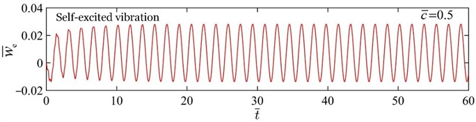
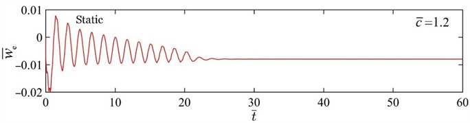
Fig. 2 presents two typical motion states of the beam, i.e., the self-excited vibration state and the static state. In the computation, we set 5, 0.01, 0.001, and 1.2. For 0.5, the beam initially exhibits an irregular transient response. After a period of evolution, the beam eventually reaches a periodic vibration state with stable amplitude and period, as shown in Fig. 2(a). For 1.2, the beam initially vibrates up and down. Because the damping of the beam is greater than the driving torque, the amplitude gradually decreases and eventually develops into a static state, as shown in Fig. 2(b). The transition between the static state and the self-excited vibration state is governed by the competition between the thermally induced bending torque and the damping torque.
Fig. 2Variation of the beam endpoint deflection with time for two typical motion states. The parameters are set as T̄= 5, C̄0= 0.01, w̄0= 0.001, and h̄= 1.2. The transition between the static state and the self-excited vibration state is governed by the competition between the thermally induced bending torque and the damping torque
a) Self-excited vibration state ( 0.5)
b) Static state ( 1.2)
3.2. Mechanism of the beam self-excited vibration
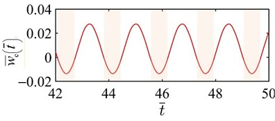
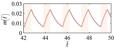
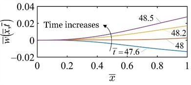
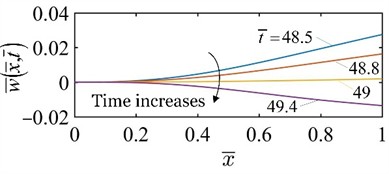
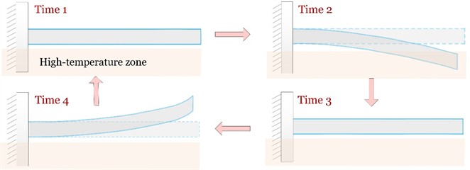
Fig. 3 illustrates the mechanism of thermally induced self-excited vibration of the beam for 5, 0.01, 0.001, 0.5, and 1.2. The shaded areas in Fig. 3(a) and (b) indicate that the beam is in the high-temperature zone. Fig. 3(a) shows the variation of the endpoint deflection with time , and the deflection exhibits a periodic variation with respect to time during the steady-state self-excited vibration. As depicted in Fig. 3(b), when the beam enters the high-temperature zone, the thermally induced bending torque increases rapidly. Conversely, as the beam exits the high-temperature zone, the bending torque decreases. Fig. 3(c) and (d) present the deflection curves of the beam in relation to time, which correspond to one vibration period in Fig. 3(a). The results demonstrate that the displacement of each point in the beam changes periodically throughout the self-excited vibration process. Fig. 3(e) illustrates the snapshots of the beam during one period of the self-excited vibration. The coupling between beam motion and the periodic variation of the thermally induced bending torque leads to self-excited vibration. From the perspective of energy balance, the onset mechanism of self-excited vibration is consistent with the classical theory of self-oscillation. Specifically, when the net work done by the thermally induced bending torque exceeds the energy dissipated by damping within one vibration cycle, the system eventually evolves into a stable self-excited vibration state. The steady-state amplitude is determined by the competition between the net work and damping dissipation.
Fig. 3Mechanism of the thermally induced self-excited vibration of the beam under the specified parameters T̄= 5, C̄0= 0.01, w̄0= 0.001, c̄= 0.5, and h̄= 1.2. The shaded areas in a) and b) indicate that the beam is in the high-temperature zone
a) The variation of with time
b) The variation of with time
c) The deflection curves of the beam
d) The deflection curves of the beam
e) Snapshots of the beam during one vibration period
4. Parametric analysis
We define the difference between the highest and lowest positions of the beam endpoint during vibration as the amplitude of the beam, and the time interval between two adjacent peaks or valleys in the time-history curve as one vibration period. The triggering condition, amplitude, and period of the self-excited vibration are influenced by various factors such as the temperature, thermal expansion coefficient, the damping, the characteristic parameter , and the distance between the lower surface of the beam and the high-temperature zone. In the following, the effects of different parameters on the self-excited vibration of the beam are quantitatively investigated through numerical simulations, and the critical conditions for triggering the beam vibration are determined.
4.1. Effect of the temperature in the high-temperature zone
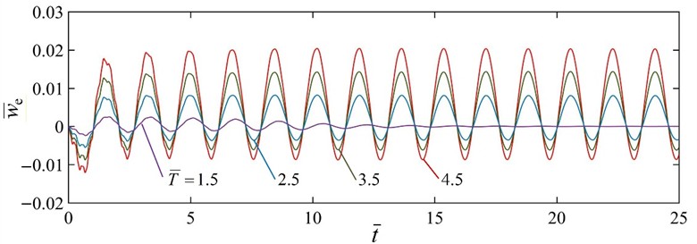
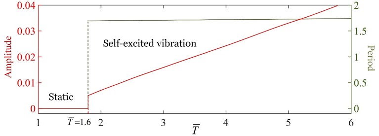
Fig. 4 depicts the effects of the temperature in the high-temperature zone on the amplitude and period of the self-excited vibration for 0.01, 0.001, 0.5, and 1.2. The steady-state amplitude of the beam increases as the temperature increases. Fig. 4(a) illustrates the dependence of the endpoint deflection on time for four different temperatures . The results show that the endpoint deflection increases with increasing temperature. For 1.5, the beam evolves into a static state. Fig. 4(b) displays the dependence of amplitude and period on the temperature . For 1.6, the beam is in the static state. This is because the thermal energy obtained by the beam from the environment is insufficient to compensate for the energy dissipated by damping. For 1.6, the beam is in the self-excited vibration state, and as the thermally induced bending torque increases, the amplitude approximately increases linearly, while the period remains constant. There exists a critical temperature 1.6 for triggering the beam self-excited vibration. Since , a larger value of corresponds to a larger temperature difference between the beam and the environment, which is beneficial for generating self-excited vibration. This behavior arises because the thermally induced bending torque of the beam increases with increasing ambient temperature difference, thereby increasing the energy input during one vibration cycle.
Fig. 4Effect of the dimensionless temperature in high-temperature zone on the self-excited vibration. The parameters are set as C̄0= 0.01, w̄0= 0.001, c̄= 0.5, and h̄= 1.2. There exists a critical temperature T̄= 1.6 for triggering the beam self-excited vibration
a) The time histories of the endpoint deflection for four different temperatures
b) Effects of the temperature on the amplitude and period of the self-excited vibration
4.2. Effect of the dimensionless thermal expansion coefficient
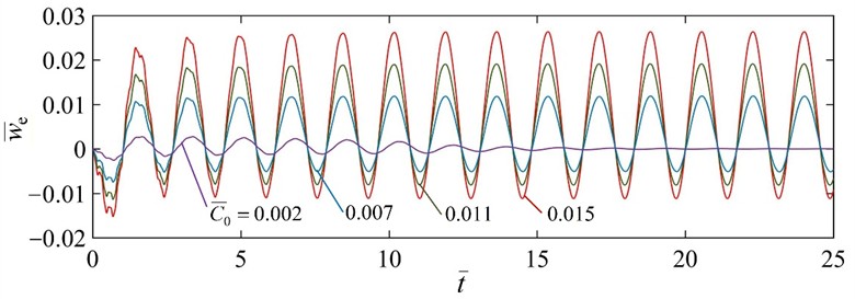
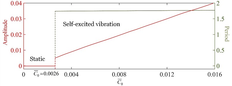
Fig. 5 depicts the effects of the dimensionless thermal expansion coefficient on the amplitude and period of the self-excited vibration by setting 4, 0.002, 0.5, and 1.2. The amplitude of the beam in steady state increases with increase of . There exists a lower limit of thermal expansion coefficient 0.0026 for triggering the beam self-excited vibration. Fig. 5(a) presents the dependence of deflection at the endpoint of the beam on time for 0.002, 0.007, 0.011, and 0.015. This result indicates that a greater leads to a greater endpoint deflection. For 0.002, the beam evolves into a static state. Fig. 5(b) quantitatively illustrates the effects of the thermal expansion coefficient on the amplitude and period of the steady-state self-excited vibration. For 0.0026, the beam is in the static state, where the vibration amplitude is zero and no oscillation period exists. For 0.0026, the beam is in the self-excited vibration state, as increases, the amplitude approximately increases linearly, while the period remains constant. By combining Eq. (4) we can easily understand that the driving torque increases with increase of thermal expansion coefficient.
Fig. 5Effect of the dimensionless thermal expansion coefficient on the self-excited vibration by setting T̄= 4, w̄0= 0.002, c̄= 0.5, and h̄= 1.2. There exists a lower limit of thermal expansion coefficient C̄0= 0.0026 for triggering the beam self-excited vibration
a) The endpoint deflection with time for four different thermal expansion coefficients
b) Dependence of the amplitude and period on the thermal expansion coefficient
4.3. Effect of the dimensionless characteristic parameter
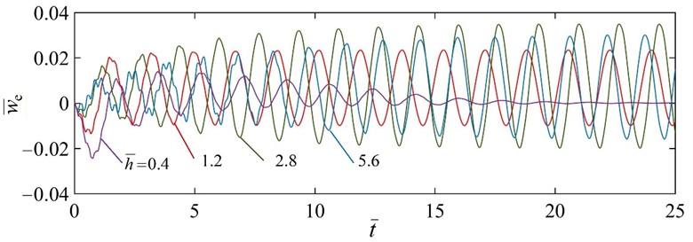
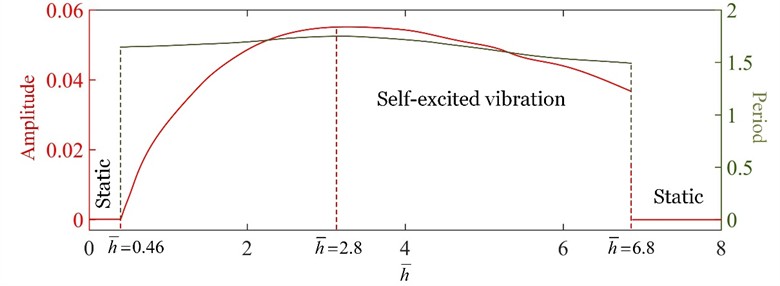
Fig. 6 depicts the effects of the dimensionless on the amplitude and period of the self-excited vibration in steady state. In the theoretical prediction, we set 5, 0.01, 0.001, and 0.5. There exists a lower limit of 0.46 and an upper limit of 6.8 for triggering the beam self-excited vibration. The amplitude of the beam in steady state first increases and then decreases with increase of . There exists an optimum 2.8 that maximizes the amplitude of the beam. As depicted in Fig. 6(a), the amplitude of the beam is greater for 2.8 than for both 1.2 and 5.6. For 0.4, the beam evolves into a static state. Fig. 6(b) quantitatively displays the dependence of amplitude and period on . For 0.46, both the amplitude and period of the vibration in steady state are zero, and the beam is in the static state. The reason for this phenomenon is that, when 0.46, the thermally induced bending torque increases too slowly after the beam enters the high-temperature zone, resulting in insufficient net work performed by the bending torque during one vibration cycle to compensate for the damping dissipation. For 0.46 6.8, the beam is in the self-excited vibration state, both the amplitude and period first increase and then decrease with increase of the characteristic parameter . When 2.8, the period and amplitude of the beam in the steady state are maximum. For 6.8, the amplitude and period of the beam abruptly change to zero, and the system is in the static state. This is because, when 6.8, the thermally induced bending torque changes almost instantaneously. Although the bending torque changes rapidly, its effective working time during one period is reduced, resulting in a decrease in the net work performed by the bending torque. Consequently, the net energy input per cycle becomes insufficient to compensate for damping dissipation, and the self-excited vibration disappears.
Fig. 6Effect of the dimensionless characteristic parameter h̄ on the self-excited vibration under the parameters T̄= 5, C̄0= 0.01, w̄0= 0.001, and c̄= 0.5. There exists a lower limit of h̄= 0.46 and an upper limit of h̄= 6.8 for triggering the beam self-excited vibration
a) The endpoint deflection with time for 0.4, 1.2, 2.8, and 5.6
b) The dependence of amplitude and period on
4.4. Effect of the distance between the lower surface of the beam and the high-temperature zone
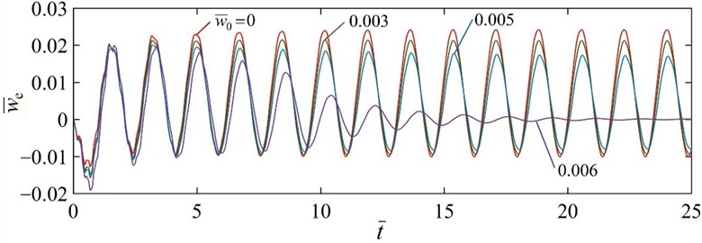
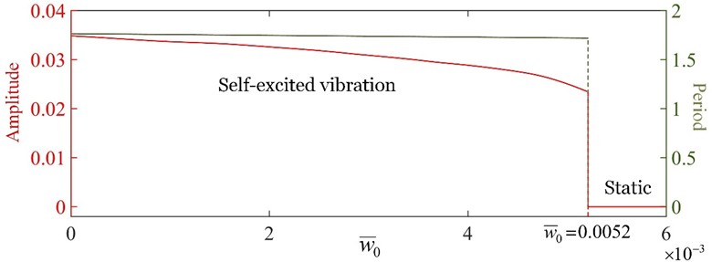
Fig. 7 presents the effect of the distance between the lower surface of the beam and the high-temperature zone on the self-excited vibration for 5, 0.01, 1.2, and 0.5. The amplitude of the beam in steady state decreases with increase of . There exists an upper limit of 0.0052 for triggering the beam self-excited vibration. As shown in Fig. 7(a), the endpoint deflection decreases as increases. For 0.006, the beam evolves into a static state. Fig. 7(b) depicts the dependence of the amplitude and period on . For 0.0052, the beam is in the self-excited vibration state. As increases, the amplitude decreases while the period remains constant. This is because a larger distance between the lower surface of the beam and the high-temperature zone results in a longer transition time for the beam to experience the thermally induced bending torque variation during one oscillation cycle. For 0.0052, the amplitude and period of the beam abruptly change to zero, and the beam is in the static state. This is because the high-temperature zone is sufficiently far from the beam, resulting in an insufficient thermally induced bending torque to sustain oscillation. The analysis in this section also provides a theoretical reference for thermally expandable cantilever beams operating in different environments, such as high-temperature liquids.
Fig. 7Effect of the distance between the lower surface of the beam and the high-temperature zone on the self-excited vibration. The parameters are set as T̄= 5, C̄0= 0.01, h̄= 1.2, and c̄= 0.5. There exists an upper limit of w̄0= 0.0052 for triggering the beam self-excited vibration
a) The endpoint deflection with time for 0, 0.003, 0.005, and 0.006
b) Dependence of the amplitude and period on
4.5. Effect of the damping coefficient
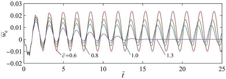
Fig. 8 depicts the effects of the damping coefficient on the amplitude and period of the steady-state self-excited vibration under the given parameters 5, 0.01, 0.001, and 1.2. As the damping coefficient increases, the amplitude of the beam in steady state decreases. There exists a critical damping coefficient 1.12 for triggering the beam self-excited vibration. Fig. 8(a) depicts the dependence of the endpoint deflection on time for four different damping coefficients . For 0.6, 0.8, and 1.0, the endpoint deflection decreases as the damping coefficient increases. For 1.3, the beam evolves into a static state. Fig. 8(b) quantitatively illustrates the effects of the damping coefficient on the amplitude and period. For 1.12, the system is in the self-excited vibration state, and as the damping coefficient increases, the amplitude decreases and the period decreases slightly. For 1.12, the system is in the static state, both the amplitude and period of the beam in steady state are zero. This result indicates that increasing the damping coefficient suppresses the self-excited vibration of the beam.
Fig. 8Effect of the damping coefficient c̄ on the self-excited vibration under the given parameters T̄= 5, C̄0= 0.01, w̄0= 0.001, and h̄= 1.2. There exists a critical damping coefficient c̄= 1.12 for triggering self-excited vibration
a) The endpoint deflection with time for four different damping coefficients
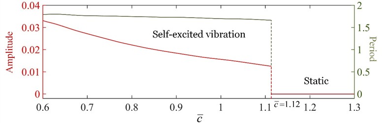
b) Effects of the damping coefficient on the amplitude and period of the self-excited vibration
5. Conclusions
Thermally responsive polymers can absorb thermal energy directly from the environment to maintain self-sustained motion without the need for additional control equipment. This study proposes a novel thermally expandable cantilever beam capable of self-excited vibration under a steady temperature difference. A unique self-excitation mechanism is revealed, in which the beam motion between high-temperature and low-temperature zones induces the position-dependent switching of the thermally induced bending torque. The governing equation for the self-excited vibration of the beam is derived and solved using the modal superposition method. Numerical calculations reveal that the beam has two typical motion states, namely, the static state and the self-excited vibration state. The analysis of the underlying self-excitation mechanism indicates that the interaction between the beam motion and the periodic switching of the thermally induced bending torque is responsible for sustaining the self-excited vibration.
The quantitative parametric study demonstrates that the steady-state amplitude increases with both the temperature in the high-temperature zone and the thermal expansion coefficient , whereas it decreases with the distance between the beam and the high-temperature zone and the damping coefficient . In contrast, the amplitude exhibits a non-monotonic dependence on the characteristic parameter , first increasing and then decreasing as increases. In addition, the period of the self-excited vibration is primarily affected by the characteristic parameter , while other parameters have a slight influence on the period. The major contribution of this work lies in proposing a novel thermally expandable cantilever beam driven by a steady temperature difference and revealing its unique self-excitation mechanism from the coupling between beam motion and position-dependent switching of thermally induced bending torque. The critical thresholds and parametric laws obtained quantitatively can provide direct theoretical guidance for the design of micro-robotics, energy harvesting systems and active motors. It should be noted that the present work mainly focuses on theoretical modeling and numerical analysis, and experimental validation has not yet been conducted. Future work will focus on the experimental realization of the proposed thermally expandable cantilever beam, validation of the mechanism underlying the self-excited vibration, and systematic comparison between experimental results and theoretical predictions.
References
-
H. Mickoski, I. Mickoski, and F. Zdraveski, “Investigation of self-excited vibrations in tread brake unit for railway vehicles,” Journal of Vibroengineering, Vol. 18, No. 6, pp. 3881–3890, Sep. 2016, https://doi.org/10.21595/jve.2016.16914
-
A. Jenkins, “Self-oscillation,” Physics Reports, Vol. 525, No. 2, pp. 167–222, Apr. 2012, https://doi.org/10.1016/j.physrep.2012.10.007
-
M. Dakel and J.-J. Sinou, “Stability and nonlinear self-excited friction-induced vibrations for a minimal model subjected to multiple coalescence patterns,” Journal of Vibroengineering, Vol. 19, No. 1, pp. 604–628, Feb. 2017, https://doi.org/10.21595/jve.2016.17190
-
J. Chen, Y. Qiu, X. Zhou, D. Ge, and K. Li, “Impatiens-inspired self-sustained photo-ejector with liquid crystal elastomer shell,” Thin-Walled Structures, Vol. 219, p. 114312, Nov. 2025, https://doi.org/10.1016/j.tws.2025.114312
-
A. L. Igumnov, S. V. Metrikin, K. A. Lyubimov, F. V. Ovchinnikov, and V. A. Grezina, “On the self-excitation of vibrations of a boring bar in the process of deep boring,” Journal of Vibroengineering, Vol. 20, No. 5, pp. 2001–2011, Aug. 2018, https://doi.org/10.21595/jve.2017.18487
-
G. Panovko and A. Shokhin, “Self-synchronization features of inertial vibration exciters in two-mass system,” Journal of Vibroengineering, Vol. 21, No. 2, pp. 498–506, Mar. 2019, https://doi.org/10.21595/jve.2019.20083
-
X. Zhou et al., “Multimodal autonomous locomotion of liquid crystal elastomer soft robot,” Advanced Science, Vol. 11, No. 23, p. 2402358, Jun. 2024, https://doi.org/10.1002/advs.202402358
-
H. S. Bauomy, “Active control impact analysis on shaped coupled beam structure,” AIMS Mathematics, Vol. 10, No. 12, pp. 30732–30772, Dec. 2025, https://doi.org/10.3934/math.20251349
-
C. Du, Q. Cheng, K. Li, and Y. Yu, “A light-powered liquid crystal elastomer spring oscillator with self-shading coatings,” Polymers, Vol. 14, No. 8, p. 1525, Apr. 2022, https://doi.org/10.3390/polym14081525
-
H. S. B. Abdelmonem, “Dual nonlinear saturation control of electromagnetic suspension (EMS) system in Maglev trains,” Mathematics, Vol. 14, No. 1, p. 62, Dec. 2025, https://doi.org/10.3390/math14010062
-
C. Li, L. Xu, Y. Dai, and Y. Dai, “A light-driven self-spinning and translation disc exploiting photothermal liquid crystal elastomers,” Micromachines, Vol. 17, No. 3, p. 284, Feb. 2026, https://doi.org/10.3390/mi17030284
-
H. S. Bauomy and A. T. El-Sayed, “Oscillation controlling in nonlinear motorcycle scheme with bifurcation study,” Mathematics, Vol. 13, No. 19, p. 3120, Sep. 2025, https://doi.org/10.3390/math13193120
-
W. Liao and Z. Yang, “The integration of sensing and actuating based on a simple design fiber actuator towards intelligent soft robots,” Advanced Materials Technologies, Vol. 7, No. 6, p. 2101260, Nov. 2021, https://doi.org/10.1002/admt.202101260
-
Z. Asilehan et al., “Light-driven dancing of nematic colloids in fractional skyrmions and bimerons,” Nature Communications, Vol. 16, No. 1, p. 1148, Jan. 2025, https://doi.org/10.1038/s41467-025-56263-5
-
X. Zhou et al., “Geometrically insensitive deform-and-go liquid crystal elastomer actuators through controlled radical diffusion,” Nature Communications, Vol. 16, No. 1, p. 7536, Aug. 2025, https://doi.org/10.1038/s41467-025-62883-8
-
J. Chen, Q. Ye, J. Tian, Y. Bao, and K. Li, “Cat-inspired self-adaptive liquid crystal elastomer photo-jumper,” Thin-Walled Structures, Vol. 225, p. 114756, Mar. 2026, https://doi.org/10.1016/j.tws.2026.114756
-
C. Du, S. Cen, and S. Dai, “Synchronous oscillation of a mass block and a turn-plate actuated by a heat-activated elastomer fiber,” Thin-Walled Structures, Vol. 230, p. 115258, Jun. 2026, https://doi.org/10.1016/j.tws.2026.115258
-
H. Zeng, O. M. Wani, P. Wasylczyk, R. Kaczmarek, and A. Priimagi, “Self‐regulating iris based on light‐actuated liquid crystal elastomer,” Advanced Materials, Vol. 29, No. 30, p. 1701814, Jun. 2017, https://doi.org/10.1002/adma.201701814
-
C. Bai, J. Kang, and Y. Q. Wang, “Light-induced motion of three-dimensional pendulum with liquid crystal elastomeric fiber,” International Journal of Mechanical Sciences, Vol. 266, p. 108911, Dec. 2023, https://doi.org/10.1016/j.ijmecsci.2023.108911
-
K. Li, J. Xiang, Z. Zhang, and Y. Dai, “Logic-inspired bistable liquid crystal elastomer photo-oscillator via magnetic-photothermal coupling,” Thin-Walled Structures, Vol. 225, p. 114759, Mar. 2026, https://doi.org/10.1016/j.tws.2026.114759
-
S. Palagi et al., “Structured light enables biomimetic swimming and versatile locomotion of photoresponsive soft microrobots,” Nature Materials, Vol. 15, No. 6, pp. 647–653, Jun. 2016, https://doi.org/10.1038/nmat4569
-
Y.-Y. Xiao, Z.-C. Jiang, J.-B. Hou, and Y. Zhao, “Desynchronized liquid crystalline network actuators with deformation reversal capability,” Nature Communications, Vol. 12, No. 1, p. 624, Jan. 2021, https://doi.org/10.1038/s41467-021-20938-6
-
X. Fang, J. Lou, J. Wang, K.-C. Chuang, H. M. Wu, and Z. L. Huang, “A self-excited bistable oscillator with a light-powered liquid crystal elastomer,” International Journal of Mechanical Sciences, Vol. 271, p. 109124, Feb. 2024, https://doi.org/10.1016/j.ijmecsci.2024.109124
-
L. Yang et al., “An autonomous soft actuator with light-driven self-sustained wavelike oscillation for phototactic self-locomotion and power generation,” Advanced Functional Materials, Vol. 30, No. 15, p. 1908842, Apr. 2020, https://doi.org/10.1002/adfm.201908842
-
J. Chen, X. Wang, and K. Li, “Dissipation-mediated liquid crystal elastomer self-jumper under constant illumination,” Chaos, Solitons and Fractals, Vol. 208, p. 118176, Jul. 2026, https://doi.org/10.1016/j.chaos.2026.118176
-
Z. Li, D. Xia, M. Lei, and H. Yan, “Numerical investigation on self-propelled hydrodynamics of squid-like multiple tentacles with synergistic expansion,” Ocean Engineering, Vol. 287, p. 115808, Sep. 2023, https://doi.org/10.1016/j.oceaneng.2023.115808
-
L. Chen, Y. Xia, Z. Tang, J. Zhao, and K. Zhou, “Self-sustaining chaotic characteristics of double pendulum based on self-shading effect,” Chaos, Solitons and Fractals, Vol. 208, p. 118031, Jul. 2026, https://doi.org/10.1016/j.chaos.2026.118031
-
Z. Li, D. Xia, S. Kang, Y. Li, and T. Li, “A comparative study of multi-tentacled underwater robot with different self-steering behaviors: maneuvering and cruising modes,” Physics of Fluids, Vol. 36, No. 11, p. 115118, Nov. 2024, https://doi.org/10.1063/5.0237446
-
F. Qi, C. Zhou, H. Qing, H. Sun, and J. Yin, “Aerial track‐guided autonomous soft ring robot,” Advanced Science, Vol. 12, No. 26, p. 2503288, Apr. 2025, https://doi.org/10.1002/advs.202503288
-
J. Ma and Z. Yang, “Smart liquid crystal elastomer fibers,” Matter, Vol. 8, No. 2, p. 101950, Feb. 2025, https://doi.org/10.1016/j.matt.2024.101950
-
F. Qi, Y. Li, Y. Hong, Y. Zhao, H. Qing, and J. Yin, “Defected twisted ring topology for autonomous periodic flip-spin-orbit soft robot,” Proceedings of the National Academy of Sciences, Vol. 121, No. 3, p. e2312680121, Jan. 2024, https://doi.org/10.1073/pnas.2312680121
-
H. Yang, X. Yin, C. Zhang, B. Chen, P. Sun, and Y. Xu, “Weaving liquid crystal elastomer fiber actuators for multifunctional soft robotics,” Science Advances, Vol. 11, No. 8, p. eads3058, Feb. 2025, https://doi.org/10.1126/sciadv.ads3058
-
L. Wei, X. Jiang, X. Hu, D. Ge, and K. Li, “Gravity-independent self-rolling of a photothermal liquid crystal elastomer rod for microgravity actuation,” Communications in Nonlinear Science and Numerical Simulation, Vol. 157, p. 109764, Jan. 2026, https://doi.org/10.1016/j.cnsns.2026.109764
-
K. Li, C. Du, Q. He, and S. Cai, “Thermally driven self-oscillation of an elastomer fiber with a hanging weight,” Extreme Mechanics Letters, Vol. 50, p. 101547, Dec. 2021, https://doi.org/10.1016/j.eml.2021.101547
-
C. Du, S. Cen, and S. Dai, “Modeling of a self-swimming thick-walled liquid crystal elastomer ring with a paddle on a hot liquid surface,” Chaos, Solitons and Fractals, Vol. 201, p. 117256, Dec. 2025, https://doi.org/10.1016/j.chaos.2025.117256
-
J. Sun, Y. Wang, W. Liao, and Z. Yang, “Ultrafast, high‐contractile electrothermal‐driven liquid crystal elastomer fibers towards artificial muscles,” Small, Vol. 17, No. 44, p. 2103700, Sep. 2021, https://doi.org/10.1002/smll.202103700
-
W. Kang, Q. Cheng, C. Liu, Z. Wang, D. Li, and X. Liang, “A constitutive model of monodomain liquid crystal elastomers with the thermal-mechanical-nematic order coupling,” Journal of the Mechanics and Physics of Solids, Vol. 196, p. 105995, Dec. 2024, https://doi.org/10.1016/j.jmps.2024.105995
-
C. Du, S. Dai, and Q. Sun, “Theoretical modeling of a bionic arm with elastomer fiber as artificial muscle controlled by periodic illumination,” Polymers, Vol. 17, No. 15, p. 2122, Jul. 2025, https://doi.org/10.3390/polym17152122
-
C. Du, Q. Cheng, K. Li, and Y. Yu, “Self-sustained collective motion of two joint liquid crystal elastomer spring oscillator powered by steady illumination,” Micromachines, Vol. 13, No. 2, p. 271, Feb. 2022, https://doi.org/10.3390/mi13020271
-
C. Bai, J. Kang, and Y. Q. Wang, “Kirigami-inspired light-responsive conical spiral actuators with large contraction ratio using liquid crystal elastomer fiber,” ACS Applied Materials and Interfaces, Vol. 17, No. 9, pp. 14488–14498, Feb. 2025, https://doi.org/10.1021/acsami.4c20234
-
Y. Wang et al., “Repeatable and reprogrammable shape morphing from photoresponsive gold nanorod/liquid crystal elastomers,” Advanced Materials, Vol. 32, No. 46, p. 2004270, Oct. 2020, https://doi.org/10.1002/adma.202004270
-
H. Zhao et al., “Spatiotemporally programmed dielectric liquid crystal elastomer: electro-reversible 3D morphing via inverse 4D printing,” Science Advances, Vol. 11, No. 48, p. eaeb2289, Nov. 2025, https://doi.org/10.1126/sciadv.aeb2289
-
D. Wang et al., “Dexterous electrical-driven soft robots with reconfigurable chiral-lattice foot design,” Nature Communications, Vol. 14, No. 1, p. 5067, Aug. 2023, https://doi.org/10.1038/s41467-023-40626-x
-
M. G. B. Atia, A. Mohammad, A. Gameros, D. Axinte, and I. Wright, “Reconfigurable soft robots by building blocks,” Advanced Science, Vol. 9, No. 33, p. 2203217, Oct. 2022, https://doi.org/10.1002/advs.202203217
-
M. Zheng, D. Wang, D. Zhu, S. Cao, X. Wang, and M. Zhang, “PiezoClimber: versatile and self-transitional climbing soft robot with bioinspired highly directional footpads,” Advanced Functional Materials, Vol. 34, No. 6, p. 2308384, Feb. 2023, https://doi.org/10.1002/adfm.202308384
-
L. Hong, H. Zhang, T. Kraus, and P. Jiao, “Ultra-stretchable kirigami piezo-metamaterials for sensing coupled large deformations,” Advanced Science, Vol. 11, No. 5, p. 2303674, Feb. 2023, https://doi.org/10.1002/advs.202303674
-
S. Zhu, Y. Huang, and B. Fang, “Progress and prospect for conducting polymer fibers,” Advanced Materials, Vol. 37, No. 48, p. e04071, Jul. 2025, https://doi.org/10.1002/adma.202504071
-
J. Li and L. Wang, “Modeling magnetic soft continuum robot in nonuniform magnetic fields via energy minimization,” International Journal of Mechanical Sciences, Vol. 282, p. 109688, Aug. 2024, https://doi.org/10.1016/j.ijmecsci.2024.109688
-
P. Duhr et al., “Kirigami makes a soft magnetic sheet crawl,” Advanced Science, Vol. 10, No. 25, p. 2301895, Jun. 2023, https://doi.org/10.1002/advs.202301895
-
J. Zhao et al., “Insect-scale biped robots based on asymmetrical friction effect induced by magnetic torque,” Advanced Materials, Vol. 36, No. 24, p. 2312655, Jun. 2024, https://doi.org/10.1002/adma.202312655
-
Z. Zheng, J. Han, Q. Shi, S. O. Demir, W. Jiang, and M. Sitti, “Single-step precision programming of decoupled multiresponsive soft millirobots,” Proceedings of the National Academy of Sciences, Vol. 121, No. 13, p. e2320386121, Mar. 2024, https://doi.org/10.1073/pnas.2320386121
-
L. Zhou, C. Du, W. Wang, and K. Li, “A thermally-responsive fiber engine in a linear temperature field,” International Journal of Mechanical Sciences, Vol. 225, p. 107391, May 2022, https://doi.org/10.1016/j.ijmecsci.2022.107391
-
P. Shi et al., “Air plastron-enabled heat management for enhanced photothermal actuation in underwater soft robots,” Science Advances, Vol. 11, No. 33, p. eadx7189, Aug. 2025, https://doi.org/10.1126/sciadv.adx7189
-
S. Ma et al., “4D-Printed adaptive and programmable shape-morphing batteries,” Advanced Materials, Vol. 37, No. 30, p. 2505018, May 2025, https://doi.org/10.1002/adma.202505018
-
C. Du, B. Zhang, Q. Cheng, P. Xu, and K. Li, “Thermally driven self-rotation of a hollow torus motor,” Micromachines, Vol. 13, No. 3, p. 434, Mar. 2022, https://doi.org/10.3390/mi13030434
-
X. Li et al., “Leaf vein-inspired programmable superstructure liquid metal photothermal actuator for soft robots,” Advanced Materials, Vol. 37, No. 18, p. 2416991, May 2025, https://doi.org/10.1002/adma.202416991
-
J. Che, X. Yang, J. Peng, J. Li, Z. Liu, and M. Qi, “Arc-heating actuated active-morphing insect robots,” Nature Communications, Vol. 16, No. 1, p. 3014, Mar. 2025, https://doi.org/10.1038/s41467-025-58258-8
-
Q. Wang et al., “Strategies for continuous responsive motion in a constant environment,” Advanced Materials, Vol. 37, No. 39, p. 2502926, Jul. 2025, https://doi.org/10.1002/adma.202502926
-
L. Xu et al., “Body temperature actuated liquid crystal elastomers from hyper tensile preprogramming,” Advanced Functional Materials, Vol. 35, No. 48, p. 2424033, Jun. 2025, https://doi.org/10.1002/adfm.202424033
-
B. Chen, C. Liu, Z. Xu, Z. Wang, and R. Xiao, “Modeling the thermo-responsive behaviors of polydomain and monodomain nematic liquid crystal elastomers,” Mechanics of Materials, Vol. 188, p. 104838, Nov. 2023, https://doi.org/10.1016/j.mechmat.2023.104838
-
Y. Zheng, S. Zhang, Y. Yuan, and C. Li, “Hierarchical engineering of amphiphilic peptides nanofibrous crosslinkers toward mechanically robust, functionally customable, and sustainable supramolecular hydrogels,” Advanced Materials, Vol. 37, No. 30, p. 2503324, May 2025, https://doi.org/10.1002/adma.202503324
-
X. Yang, M. Du, Z. Chu, and C. Li, “Synchronizing multicolor changes and shape deformation into structurally homogeneous hydrogels via a single photochromophore,” Advanced Materials, Vol. 37, No. 16, p. 2500857, Mar. 2025, https://doi.org/10.1002/adma.202500857
-
Y. Zhao et al., “Physically intelligent autonomous soft robotic maze escaper,” Science Advances, Vol. 9, No. 36, p. eadi3254, Sep. 2023, https://doi.org/10.1126/sciadv.adi3254
-
A. Baumann et al., “Motorizing fibres with geometric zero-energy modes,” Nature Materials, Vol. 17, No. 6, pp. 523–527, Apr. 2018, https://doi.org/10.1038/s41563-018-0062-0
-
Y. Yu, C. Du, K. Li, and S. Cai, “Controllable and versatile self-motivated motion of a fiber on a hot surface,” Extreme Mechanics Letters, Vol. 57, p. 101918, Nov. 2022, https://doi.org/10.1016/j.eml.2022.101918
-
Y. Yu, F. Liu, C. Huang, and K. Li, “Self-swing of a thermo-responsive L-shaped rod partially resting on a hot plate,” Thin-Walled Structures, Vol. 221, p. 114464, Dec. 2025, https://doi.org/10.1016/j.tws.2025.114464
-
G. Vantomme et al., “Coupled liquid crystalline oscillators in Huygens’ synchrony,” Nature Materials, Vol. 20, No. 12, pp. 1702–1706, Feb. 2021, https://doi.org/10.1038/s41563-021-00931-6
-
S. Serak, N. Tabiryan, R. Vergara, T. J. White, R. A. Vaia, and T. J. Bunning, “Liquid crystalline polymer cantilever oscillators fueled by light,” Soft Matter, Vol. 6, No. 4, pp. 779–783, Dec. 2009, https://doi.org/10.1039/b916831a
-
Z. Wan, S. Li, Q. Huang, and T. Wang, “Structural response reconstruction based on the modal superposition method in the presence of closely spaced modes,” Mechanical Systems and Signal Processing, Vol. 42, No. 1-2, pp. 14–30, Sep. 2013, https://doi.org/10.1016/j.ymssp.2013.07.007
About this article

The authors have not disclosed any funding.
The datasets generated during and/or analyzed during the current study are available from the corresponding author on reasonable request.
Changshen Du: conceptualization, methodology, writing-original draft preparation, software. Caifeng Zhang: writing-review and editing, methodology, funding acquisition, resources, formal analysis.
The authors declare that they have no conflict of interest.

