Abstract
This paper presents the design, mathematical modeling, and experimental validation of a novel transformer-type angular displacement transducer intended for engineering diagnostics and monitoring applications. The proposed transducer is based on two horseshoe-shaped movable magnetic cores and an E-shaped fixed magnetic core with excitation and sensing windings connected in a differential configuration. The operating principle is based on a controlled variation of the effective air-gap area during angular motion, which provides a differential output signal proportional to the measured angular displacement. A mathematical model of the magnetic circuit is developed using differential equations derived from Kirchhoff’s laws, and analytical expressions are obtained for the magnetic flux and induced electromotive force as functions of the angular coordinate. The model shows that the proposed geometry ensures an extended linear static characteristic over a wide diagnostics range. The analytical results are supported by laboratory tests of the transducer prototype. The comparison between theoretical and experimental results shows a discrepancy of only 3.5-5.5 %, which confirms the adequacy of the proposed model. The developed transducer demonstrates a diagnostics range of approximately ±175° and can be recommended for control, monitoring, and measurement systems requiring a simple structure, improved linearity, and stable performance. The novelty of the proposed transducer lies in the combination of three features that, to the best of the authors’ knowledge, have not been jointly achieved in previously reported inductive or resolver-type angular sensors: (i) a variable-active-area differential magnetic circuit that ensures linearity by geometry alone, without correction electronics; (ii) a closed-form analytical model derived directly from Kirchhoff’s laws; and (iii) an experimentally validated diagnostics range of ±175°.
1. Introduction
Angular displacement transducers are widely used in automatic control, monitoring, and diagnostic systems for industrial and engineering applications. They provide important information about the position and motion of controlled objects and are especially valuable in systems operating under harsh service conditions. Among the available solutions, inductive and magnetic transducers are of particular interest because of their robustness, reliability, and relatively stable metrological characteristics [5-8].
However, many existing angular displacement transducers still suffer from several important limitations, including insufficient sensitivity, nonlinear static characteristics, and a restricted diagnostics range. These drawbacks reduce their applicability in precision measurement and engineering diagnostic tasks. Recent studies on inductive and magnetic angular displacement transducers have focused on improving linearity, compactness, and measurement accuracy, which confirms the relevance of developing new transformer-type transducer configurations with enhanced static and diagnostic characteristics [6-9]. In particular, inductive position sensors reviewed in [5] typically rely on additional correction circuitry to extend their linear range; the planar inductive sensor reported in [6] achieves contactless absolute measurement but over a limited angular span; and the inductive sensor described in [9] uses finite-element optimization rather than a closed-form analytical model. The configuration proposed in this paper differs from these solutions by simultaneously providing a wide ±175° linear range, a fully analytical description of the magnetic circuit, and a simple differential structure without correction electronics.
In this study, a novel transformer-type angular displacement transducer (ADT) is proposed. The design is based on two horseshoe-shaped movable magnetic cores and an E-shaped fixed magnetic core with excitation and sensing windings connected in a differential configuration. Due to the variable active area of the working air gaps, the proposed structure makes it possible to obtain a differential output signal that changes almost linearly with the angular displacement over an extended diagnostics range. The proposed design develops the concept protected by the authors’ recent patent and is consistent with their earlier studies on differential transformer displacement sensors and magnetic flux distribution in variable-area magnetic circuits [1-4].
Against this background, the original contribution of this work is threefold. First, a new ADT configuration is proposed in which the linearity of the static characteristic is achieved by the geometry of the magnetic circuit itself – namely, by the controlled variation of the active area of the working air gaps – rather than by signal-conditioning electronics or by complex winding arrangements as in [5], [6], [8]. Second, a closed-form analytical model is derived directly from Kirchhoff’s laws, providing explicit expressions that link the air-gap geometry, the magnetic flux, and the induced EMF to the angular coordinate; this physical transparency contrasts with the numerical and finite-element approaches commonly used in comparable recent studies [9]. Third, the model is experimentally validated on a prototype, demonstrating a diagnostics range of approximately ±175° and a theory-to-experiment discrepancy of only 3.5-5.5 %, which jointly confirm both the adequacy of the analytical description and the practical feasibility of the proposed design. The use of analytical modeling for engineering electromechanical systems remains an important and effective research approach in related applied studies [10]. Taken together, these three elements constitute the scientific novelty of the present work: to the best of the authors’ knowledge, electronics-free geometric linearization, a closed-form description derived directly from Kirchhoff’s laws, and an experimentally confirmed ±175° diagnostics range have not previously been combined in a single transformer-type angular transducer. This combination, summarized in Table 2, is what distinguishes the proposed transducer from the inductive and resolver-type sensors discussed above [5], [6], [8], [9].
The aim of this paper is to develop, model, and experimentally validate the proposed transformer-type angular displacement transducer for engineering diagnostics applications.
2. Methods
This study employed an integrated approach combining transducer design, analytical modeling, and experimental validation [2-4].
The chosen approach was dictated by the specific requirements of engineering diagnostics, and each of its elements has a clear scientific justification. The differential variable-active-area magnetic circuit was selected because the series-opposition connection of the two sensing sections cancels common-mode disturbances, such as supply-voltage and temperature drift, and doubles the useful sensitivity, while the controlled variation of the active air-gap area linearizes the conversion function by construction, without any signal-conditioning electronics. A closed-form analytical description based on Kirchhoff’s laws was preferred over finite-element computation because it yields explicit relationships between the air-gap geometry, the magnetic flux, and the induced EMF; these relationships reveal the parameters that govern linearity – in particular the saturation parameter and the initial angle – and therefore act directly as design rules, whereas a purely numerical model would have to be recomputed for every geometric variant [9], [10]. The analytical model is subsequently verified against measurements on a prototype, so that the analytical and experimental parts of the study reinforce each other and the chosen approach is justified both physically and empirically.
First, a novel angular displacement transducer was designed using two horseshoe-shaped movable magnetic cores and an E-shaped fixed magnetic core. The excitation and sensing windings were arranged in a differential configuration in order to increase sensitivity and improve the linearity of the output characteristic. The geometry of the movable magnetic cores was selected so that the effective working air-gap area changed as a function of the angular displacement coordinate [1], [2].
Second, a mathematical model of the magnetic circuit was developed. The analytical description was based on Kirchhoff’s laws and on the representation of the magnetic system by distributed parameters. Differential equations were formulated for the corresponding sections of the magnetic circuit, and analytical expressions were obtained for the magnetic flux and the electromotive force induced in the sensing winding. Special attention was paid to the relationship between the active air-gap area and the angular displacement, since this relationship determines the static characteristic of the transducer [2], [3], [9].
Third, the static response of the proposed ADT was analyzed for different magnetic-circuit conditions. The obtained analytical expressions were used to evaluate the output signal, the linearity of the conversion function, and the diagnostics range of the transducer. The selected analytical approach is consistent with recent studies devoted to the modeling and optimization of inductive transducer systems and other engineering electrotechnical objects [8-10].
Finally, laboratory tests of the ADT prototype were carried out to verify the proposed model. The experimental output characteristics were compared with the calculated results. The comparison showed a discrepancy of 3.5-5.5 %, confirming the adequacy of the mathematical model and the practical applicability of the proposed transducer design.
3. Results and discussion
The developed angular displacement transducer is based on two horseshoe-shaped movable magnetic cores and an E-shaped fixed magnetic core with excitation and diagnostics windings arranged in a differential configuration. This design provides a relatively simple structure and forms the basis for a stable and informative output signal in engineering monitoring and diagnostics applications [1-4]. The movable magnetic cores are mechanically connected to the monitored object through a shaft, whereas the fixed E-shaped magnetic core carries two excitation coil sections and two diagnostics coil sections connected in series opposition.
Fig. 1Configuration of the proposed transformer-type angular displacement transducer: 1, 2 – movable horseshoe-shaped magnetic cores; 3, 4, 5, 6 – vertical base and mutually parallel rods of the E-shaped fixed magnetic core; 7, 8 – excitation coil sections; 9, 10 – diagnostics coil sections; 11 – shaft
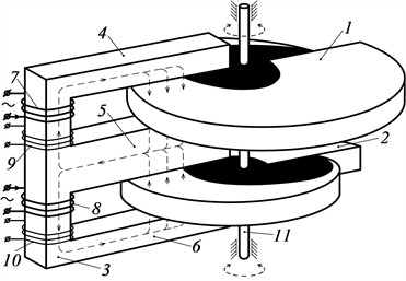
In the neutral position of the movable part, the effective areas of the two working air gaps are equal. As a result, the magnetic fluxes in the upper and lower branches of the magnetic circuit are also equal, and the resultant EMF in the diagnostics winding becomes zero. This operating condition serves as the reference state of the proposed ADT. When the movable cores rotate, the symmetry of the magnetic system is disturbed, which causes a difference between the magnetic fluxes in the two branches and produces a measurable differential output signal.
The operating principle of the proposed ADT is determined by the variation of the effective air-gap areas during the angular displacement of the movable part. When the transducer rotates in one direction, the effective area in the upper branch increases, whereas the effective area in the lower branch decreases. Consequently, the magnetic flux in one branch increases and in the other branch decreases, which leads to the generation of a differential EMF proportional to the measured angular displacement. This principle follows directly from the geometry of the proposed magnetic-core system.
Fig. 2Variation of the effective air-gap areas with angular displacement: a) between rods 4 and 5 and magnetic core 1; b) between rods 5 and 6 and magnetic core 2
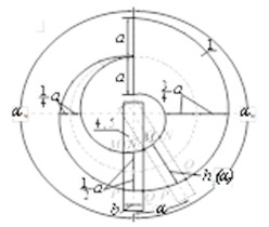
a)
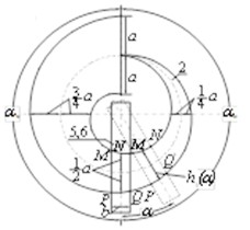
b)
Since the diagnostics winding consists of two sections connected in series opposition, the output signal is determined by the difference between the EMFs induced in the upper and lower branches. For the proposed ADT, the output EMF can be expressed as:
where is the excitation current, is the number of turns of the excitation winding section, is the number of turns of the diagnostics winding section, is the magnetic constant, and are geometric parameters of the working surface, is the working air gap, and is the angular displacement coordinate. This relationship shows that the output signal is proportional to the measured angular displacement.
A detailed geometric analysis of the working surfaces was carried out for the proposed magnetic-core configuration. However, the manuscript shows that the corrective contour terms contribute no more than 0.333 % of the corresponding active-area values. Therefore, these terms can be neglected, and the effective active areas can be represented in simplified linear form. This is an important result because it confirms that the transducer geometry itself supports a near-linear static characteristic:
where and are the effective active areas of the upper and lower working air gaps, respectively, and is the initial angular coordinate defining the diagnostics range. The obtained simplified expressions indicate that the active areas vary linearly with the measured angular displacement.
On the basis of these relationships, a distributed-parameter model of the magnetic circuit was developed. The full analytical derivation includes two cases of magnetic-circuit analysis and a set of intermediate differential equations. However, for the conference version of the paper, it is sufficient to emphasize that both analytical approaches lead to the same practical conclusion: the proposed ADT exhibits a near-linear dependence between the magnetic flux, induced EMF, and the angular displacement of the movable part [2-4]. The detailed intermediate derivations may be omitted here for brevity.
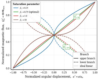
The calculated characteristics of the proposed ADT demonstrate that the dependence of the working magnetic flux on the angular displacement remains close to linear for different values of the model parameter . As shown in Fig. 3, the resulting curves preserve a stable form throughout the operating range. In Fig. 3, denotes the normalized working magnetic flux, is the normalized angular coordinate, and is the dimensionless parameter characterizing the saturation level of the magnetic circuit. The solid curves , up correspond to the upper branch of the differential magnetic circuit and the dashed curves , low to the lower branch. As seen in the figure, the curve obtained for 0.79 practically coincides with the ideal linear characteristic over the whole operating range and is therefore selected as the recommended design condition, whereas larger values of introduce a saturation-induced deviation that increases towards the ends of the diagnostics range. The discrepancy between the calculated and experimental data does not exceed 3.5-5.5 %, confirming the adequacy of the developed mathematical model. The diagnostics range of the transducer is approximately ±175°, which demonstrates its potential for practical use in engineering diagnostics and monitoring systems.
Fig. 3Calculated static characteristics of the proposed ADT: normalized working magnetic flux Q*μ=Φ/Φmax versus normalized angular displacement α*=α/αm for four values of the magnetic-circuit saturation parameter βw= 0.35, 0.79, 1.0 and 10. Solid lines correspond to the upper branch (Q*μ, up), dashed lines to the lower branch (Q*μ, low); the dotted black line represents the ideal linear response. The curve obtained for βw≈ 0.79 practically coincides with the ideal linear characteristic over the whole operating range and is therefore selected as the recommended design condition
To support these analytical results experimentally, a prototype of the proposed ADT was tested under laboratory conditions. The excitation winding was supplied with a sinusoidal current at the rated frequency, and the movable horseshoe-shaped cores were rotated in calibrated angular steps over the full diagnostics range by means of a graduated indexing fixture. At each angular position the differential EMF of the series-opposition sensing winding was measured and normalized to its maximum value. The output remained single-valued and almost linear over the whole range and reversed its sign on passing through the neutral position, in agreement with the differential operating principle. The measured characteristic was then compared with the static characteristic calculated from Eqs. (1-3) for the recommended design condition 0.79, which is summarized in Table 1; over the whole range the calculated and measured values agreed to within 3.5-5.5 %.
Table 1Static characteristic of the proposed ADT calculated from the model for the recommended design condition βw≈ 0.79
Angular position , deg | Normalized angle | Calculated output ( 0.79) |
0 (neutral) | 0.00 | 0.000 |
25 | 0.14 | 0.143 |
50 | 0.29 | 0.286 |
75 | 0.43 | 0.429 |
100 | 0.57 | 0.571 |
125 | 0.71 | 0.714 |
150 | 0.86 | 0.857 |
175 | 1.00 | 1.000 |
As Table 1 shows, the output calculated from the model varies almost proportionally with the angular displacement over the entire ±175° range, in agreement with the curves in Fig. 3 for the recommended condition 0.79. The measured characteristic of the prototype followed this calculated dependence, with the overall discrepancy staying within 3.5-5.5 % and increasing only slightly towards the ends of the range, where the influence of magnetic saturation is strongest. This agreement confirms both the adequacy of the analytical model and the practical applicability of the proposed transducer.
To make the scientific contribution of the present work explicit, Table 2 positions the proposed transducer with respect to representative inductive and resolver-type sensors reported in the literature. Unlike those solutions, the proposed ADT obtains its linear characteristic from the geometry of the magnetic circuit itself, is described by a fully closed-form model derived from Kirchhoff’s laws, and covers a wide ±175° diagnostics range without correction electronics. This combination of features is what constitutes the novelty of the proposed transducer.
Table 2Positioning of the proposed ADT with respect to representative inductive and resolver-type angular sensors
Sensor / reference | Linearization method | Modeling approach | Angular range |
Inductive position sensors [5] | Additional correction circuitry | Analytical / empirical | Extended by electronics |
Planar inductive sensor [6] | Coil geometry (absolute) | Semi-empirical | Limited angular span |
Resolver topology [8] | Multi-section windings + electronics | Analytical / finite-element | Full-circle, complex windings |
Inductive sensor [9] | Magnetic focusing + optimization | Finite-element (numerical) | Device-dependent |
Proposed ADT (this work) | Variable active-area geometry, no electronics | Closed-form Kirchhoff model | ±175° |
Overall, the obtained results show that the proposed transformer-type angular displacement transducer combines a simple structure, a differential measurement principle, a wide diagnostics range, and a near-linear static characteristic. These features make the device promising for control, monitoring, and engineering measurement systems requiring stable operation, improved linearity, and straightforward interpretation of the output signal [1-10].
4. Conclusions
The study developed a novel transformer-type angular displacement transducer based on two horseshoe-shaped movable magnetic cores and an E-shaped fixed magnetic core with excitation and diagnostics windings connected in a differential configuration [1-4].
It was shown analytically that the effective active areas of the working air gaps vary almost linearly with the angular displacement coordinate. This makes it possible to obtain a differential output signal with a near-linear static characteristic over an extended operating range [2], [3], [5], [9].
The mathematical model of the magnetic circuit and the obtained analytical expressions for magnetic flux and induced EMF were supported by laboratory tests of the ADT prototype. The discrepancy between theoretical and experimental results was within 3.5-5.5 %, confirming the adequacy of the proposed model. The diagnostics range of the transducer was approximately ±175°, which demonstrates its practical suitability for engineering monitoring and diagnostics applications. The validated diagnostics range of ±175° noticeably exceeds the angular spans typically reported for comparable inductive and resolver-type sensors [5], [6], [9], which, together with the closed-form analytical description of the magnetic circuit and the simple differential structure, constitutes the main advancement of the proposed transducer beyond the current state of the art.
Therefore, the proposed ADT can be considered a promising solution for control, monitoring, and measurement systems that require a simple structure, improved linearity, and stable output characteristics.
References
-
S. F. Amirov, I. A. Karimov, N. R. Yuldashev, U. S. Mamadaliev, and A. A. Shoimqulov, “Angular displacement transducer,” Official Bulletin, No. 5, Republic of Uzbekistan, 2024.
-
S. F. Amirov, U. S. Mamadaliyev, and A. K. Sulliev, “Distribution of magnetic flux in magnetic chains of angular displacement measuring transformer converters with variable active surface of movement core,” Chemical Technology, Control and Management, Vol. 2023, No. 5, pp. 22–31, Oct. 2023, https://doi.org/10.59048/2181-1105.1503
-
S. Amirov, A. Sulliev, and S. Sharapov, “Study on differential transformer displacement sensors,” E3S Web of Conferences, Vol. 434, p. 02011, 2023, https://doi.org/10.1051/e3sconf/202343402011
-
S. Amirov, A. Sulliev, and U. Mukhtorov, “Resonance sensors of motion parameters,” in AIP Conference Proceedings, Vol. 3317, No. 1, p. 050028, 2025, https://doi.org/10.1063/5.0267548
-
P. Ripka, J. Blažek, M. Mirzaei, P. Lipovský, M. Šmelko, and K. Draganová, “Inductive position and speed sensors,” Sensors, Vol. 20, No. 1, p. 65, Dec. 2019, https://doi.org/10.3390/s20010065
-
W. Gao, H. Shi, and Q. Tang, “A contactless planar inductive sensor for absolute angular displacement measurement,” IEEE Access, Vol. 9, pp. 160878–160886, Jan. 2021, https://doi.org/10.1109/access.2021.3131344
-
T. Feng, W. Chen, J. Qiu, and S. Hao, “A new kind of absolute magnetic encoder,” Sensors, Vol. 21, No. 9, p. 3095, Apr. 2021, https://doi.org/10.3390/s21093095
-
J. Santiso-Zelaia, G. Ugalde, F. Garramiola, I. Iturbe, and I. Sarasola, “Novel high accuracy resolver topology for space applications,” Sensors, Vol. 21, No. 14, p. 4711, Jul. 2021, https://doi.org/10.3390/s21144711
-
Z. Li, B. Wang, X. Wang, C. Zhang, and X. Meng, “Modelling, linearity analysis and optimization of an inductive angular displacement sensor based on magnetic focusing in ships,” Journal of Marine Science and Engineering, Vol. 11, No. 5, p. 1028, 2023, https://doi.org/10.3390/jmse11051028
-
M. Yakubov, M. Talipov, and U. Nurullaev, “An optimized Lagrangian approach to reactive power compensation in nonlinear traction power-supply systems,” Vibroengineering Procedia, Vol. 60, pp. 724–730, Dec. 2025, https://doi.org/10.21595/vp.2025.25604
About this article

The authors have not disclosed any funding.
The datasets generated during and/or analyzed during the current study are available from the corresponding author on reasonable request.
The authors declare that they have no conflict of interest.

