Abstract
Based on the engagement principle of the gear drive, the nonlinear transient dynamic characteristics of the planetary gearing are researched and the corresponding dynamic equilibrium equations for sun gear, planet gear and internal gear are respectively derived. Then transient engagement simulation analysis of the planetary gear train is performed in ANSYS. The corresponding stress-time curves of sun gear, planet gear and internal gear are obtained, and the worst engaging location and the ultimate stress in every gear are calculated accurately. The simulation experiment shows that the engagement characteristics of the planetary gearing at any time and in any location can be accurately analyzed by transient engagement analysis. It provides a reliable guaranty for the subsequent fatigue analysis and structural optimization of the planetary gear train.
1. Introduction
Planetary gear train has the advantages of compact structure, large transmission torque, high efficiency and stable transmission. It is one of the basic structures of the gear reducers and is widely used in various mechanical settings. During the process of high-speed rotation of the planetary gear train, the primary failure forms of the gear are tooth fracture and tooth surface fatigue pitting or gluing, which are respectively caused by the continuous actions of the tooth root bending stress and tooth surface contact stress. For this reason tooth root bending stress and tooth surface contact stress are the two basic criteria for designing planetary gear train. Therefore it is of great significance to make a thorough study of the variation rules of the bending stress and contact stress throughout the whole engagement cycle.
Many scholars have conducted related research on the strength of the planetary gear train. Wang et al. [1] performed the vibrational analysis of the planetary gear trains by finite element method. Meghdad et al. [2] used Dempster-Shafer theory to monitor the vibration condition of the planetary gear train. Li [3] and Vecchiato [4] respectively simulated the contact performance of planetary gear train by finite element analysis software. Through simulation analysis the distribution of the contact stress on each gear is obtained and the changing trend of tooth surface contact stress according to the pressure angle and radius of the planetary gear is summarized. Satoshi [5] and Ishida [6] analyzed the effect of the load and backlash on the bending stress of each gear in a planetary gear train and pinpointed the location of the maximum stress in each gear. Sundararajan [7] calculated the contact stress of the sun gear and planetary gear respectively by finite element method. Duong [8] investigated the influences of some gear structure parameters such as fillet radius, flange thickness, pressure angle and helix angle on the tooth root bending stress of the gear in a planetary gear train. Ko K. [9] revealed that it is very important to calculate the tooth root bending stress of the sun gear accurately for designing planetary gear train. However, all the above-mentioned documents did not fully consider the transient engagement characteristics of the planetary gear train. In fact both the tooth surface contact stress and tooth root bending stress are changing nonlinearly in an engagement period. It is highly necessary to study the nonlinear transient engagement characteristics of planetary gear train.
The purpose of this study is to propose a nonlinear transient dynamic analysis method for revealing the dynamic behaviors of planetary gear train. First the nonlinear transient engagement characteristics of the tooth surface contact stress and tooth root bending stress in the process of planetary gear transmission are concretely analyzed based on the principle of gear engagement. Then the transient dynamic equations of the sun gear, planetary gear and gear ring are respectively derived. Next simulation analysis is performed for illustration. Finally some typical dynamic characteristics of the planetary gear train are summarized.
2. Nonlinear engagement characteristics of planetary gear train
2.1. Nonlinear transient characteristics of the tooth surface contact stress
According to the Hertz contact theory [10], the tooth surface contact stress between a pair of gears can be calculated by the following equation:
where is the total meshing force acting on the tooth surface, is the length of the contact line, and are respectively the radiuses of curvature of the two gears at the engaging position, and are respectively the elastic modulus of the two gears, and are respectively the Poisson’s ratios of the two gears. The plus and minus signs are respectively used to show the gear pair is of external engagement or of internal engagement.
In the process of planetary gear transmission for any gear pair such as sun gear and planetary gear, gear ring and planetary gear, changes at any time, , and also exhibit nonlinear behavior. From equation (1) we can see that varies nonlinearly with the continuous change of engagement point.
2.2. Nonlinear transient characteristics of the tooth root bending stress
Fig. 1 shows the bending load acting on the tooth. As shown in Fig. 1 point A is the engagement point of the gear tooth. is the load acting on the gear tooth, which can be decomposed into a circumferential force and a radial force . is the distance from the engagement point to dangerous section , is the angle between and , is the width of the dangerous section .
Fig. 1Bending load acting on the tooth
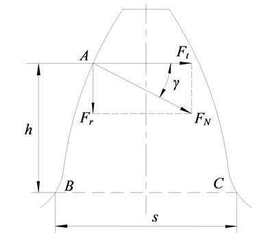
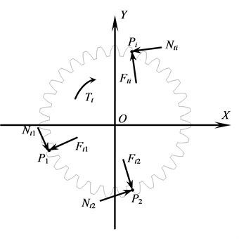
Fig. 2Loads acting on sun gear
Based on the cantilever beam theory in mechanics of materials [11], the tooth root bending stress at the dangerous section can be defined by the following equation:
where is the tooth root bending stress, is the tooth width.
During the engagement process of planetary gear and change continuously along with the rotation of planetary gear train, while also nonlinearly changes. Equation (2) shows that exhibits a nonlinear transient behavior throughout the transmission of the planetary gear train.
3. Nonlinear transient dynamic analysis of planetary gear train
3.1. Transient dynamic equilibrium equation of the sun gear
Loads acting on the sun gear are shown in Fig. 2. In order to facilitate the analysis, an auxiliary coordinate system is firstly established. The origin of the coordinate system coincides with the center of the gear. , and ( 1, 2, 3, …, ) are respectively the first, second and th engagement points between the sun gear and planetary gears. , and are respectively the friction forces at the engagement points. , and are respectively the engaging forces at each engagement point. is the torque acting on the sun gear.
According to Fig. 2, the transient dynamic equation of the sun gear can be written as:
where is the mass matrix of the sun gear, is the damping matrix, while is the stiffness matrix, , and are respectively the vectors of displacements, speeds and accelerations of all the nodes in the sun gear, is the summation of engaging forces at moment , is the summation of friction forces at moment .
At any moment the direction of is perpendicular to the tangent line of the tooth profile at the point and the value of can be calculated by the following equation:
where is the torque acting on the point , is the distance between the points and .
In a planetary gear train planetary gears are evenly distributed. Hence the torques acting on the sun gear at different engagement points are equal. Then they can be calculated by:
As for the friction force at any engagement point , its direction is parallel to the tangent line of the tooth profile and its value is defined by:
where is the friction coefficient, is the direction coefficient of the friction force at .
3.2. Transient dynamic equilibrium equation of the planetary gear
Fig. 3 shows the forces acting on the planetary gear. Points and are respectively the engagement positions with sun gear and gear ring. and are respectively the friction forces at the engagement points. and are the engaging forces at the points and .
Fig. 3Forces acting on the planetary gear
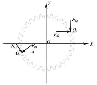
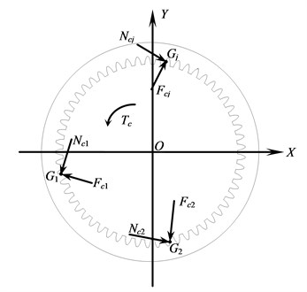
Fig. 4Loads acting on the gear ring
By establishing an auxiliary coordinate system as mentioned above, the transient dynamic equilibrium equation of the planetary gear is represented as:
where is the mass matrix of the planetary gear, is the corresponding damping matrix, while is the stiffness matrix, , and are respectively the vectors of displacements, speeds and accelerations, , and , are respectively the engaging forces and friction forces at and .
, are respectively the reactive forces of the engaging forces and friction forces acting on the sun gear at the same engagement point. Hence their values are the same. The values of the and can respectively be calculated by equations (8) and (9):
where is the torque acting on the gear ring, is the distance between the points and , is the direction coefficient of the friction force at .
3.3. Transient dynamic equilibrium equation of the gear ring
The loads acting on the gear ring are shown in Fig. 4. Here , and ( 1, 2, 3, …, ) are respectively the engagement points with corresponding planetary gear.
As introduced above, the transient dynamic equilibrium equation of the gear ring can be written as:
where is the mass matrix of the gear ring, is the damping matrix, is the stiffness matrix, , and are respectively the vectors of displacements, speeds and accelerations, is the summation of engaging forces, is the summation of friction forces. , are respectively the reactive forces of the engaging forces and friction forces acting on the corresponding planetary gear at the same engagement point. Hence their values are the same and can be calculated by the equations (8) and (9).
The displacements of the engagement points in sun gear, planetary gear and gear ring at any time t can be obtained by the equations (3)-(10). Then the corresponding strains can be obtained by using geometry equations and stresses can be calculated by using constitutive equations of the materials [12].
Equations (3), (7) and (10) show that the transient characteristics of the planetary gear train are directly related to many factors such as structure, material and loads, and the displacements, strains and stresses exhibit asynchronous nonlinear transient variation. In traditional static analysis method, sliding friction and inertial force have not been considered. At the same time the engaging characteristics of the sun gear, planetary gear and gear ring have been analyzed at the same engagement position. Hence the results can’t accord with the fact. To accurately obtain the engaging characteristics of the planetary gear train, it is essential to perform systematic nonlinear transient dynamic analysis as described above.
4. Finite element simulation example
4.1. Transient dynamic simulation of the planetary gear train
To verify the above conclusions, simulation analysis is applied by the transient dynamic analysis technique of the ANSYS software. To improve efficiency, a simplified model of the planetary gear train is built based on the following principles: (1) Select parts of the tooth of the sun gear, planetary gear and gear ring to build the FEM model. The tooth number of each gear must be accurately determined by the gear ratios to ensure that at least one tooth in each gear should pass through a complete engagement process during the simulation. (2) As the stress of the gear tooth is the primary factor which causes the gear failure, the hub and spoke of the gear can be simplified to a rigid ring.
Table 1 shows the structure parameters of a planetary gear train with fixed axes. The input power is 310 KW, the angular velocity of the sun gear is 95 r/min.
Table 1Structure parameters of the planetary gear train
Structure parameters | Sun gear | Planetary gear | Gear ring |
Tooth number | 15 | 21 | 57 |
Module /mm | 14 | ||
Pressure angle /(°) | 20 | ||
Modification coefficient | 0.51 | 0.39 | 1.289 |
Tooth width /(mm) | 155 | 150 | 150 |
Center distance /(mm) | 263 | ||
According to the method introduced above, a simplified FEM model of the planetary gear train is built as shown in Fig. 5. The model is meshed by both the mapping and sweeping modes. As the mesh density of the gear tooth is of great importance to the simulation results, all the finite element meshes of the teeth are refined to improve the simulation precision. To apply speed and torque, two inner stiffening regions are respectively formed by the inner surfaces of the sun gear and the planetary gear and their centers of rotation. Similarly an outer stiffening region is formed by the outer surface of the gear ring and its center of rotation.
Fig. 5Stiffening FEM model of planetary gear train
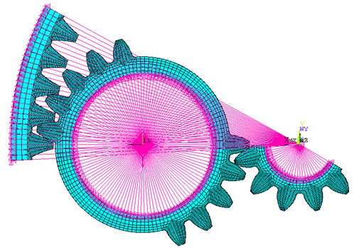
Fig. 6Contact pairs of planetary gear train
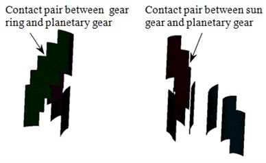
To simulate the transmission of the planetary gear system, contact pairs between planetary gear and both the gear ring and the sun gear are respectively created as shown in Fig. 6.
During the simulation process speed and torque are respectively applied to the rotary center of the input and output gears, then they are transferred to the whole gear through the corresponding stiffening regions.
At the center of each gear a revolution joint is constructed to simulate the rotation of the gear. The other freedoms of the gears are full constrained. A clockwise driving speed is applied to the sun gear, while the anticlockwise working torque is applied to the gear ring. In order to ensure the convergence speed and torque are respectively applied firstly in a slope curve and then in steady value.
Selecting the augmented Lagrange method as the contact algorithm for solving the contact problems, the transient stresses, strains and displacements of the planetary gear train throughout the whole engagement process can be obtained.
4.2. Analysis of simulation results
For any node in the tooth surface of the gear, its stress varies with the change of engagement position. Hence it is essential to perform time-history analysis to extract the maximum stress in every engagement position. Then the maximum stress and the corresponding worst engagement position throughout the complete engagement process can be determined.
Normally the materials of the sun gear, planetary gear and gear ring are different, and there is no clear change rule of contact stresses between two sets of engagement positions where the planetary gear respectively engages with the sun gear and the gear ring. Hence two time-history curves of contact stress are constructed as shown in Fig. 7.
Fig. 7Time-history curves of contact stresses
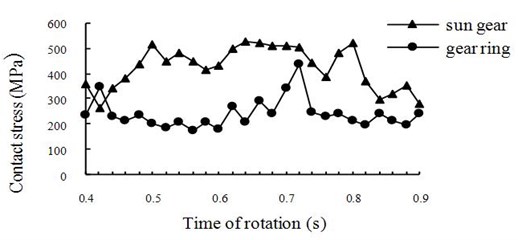
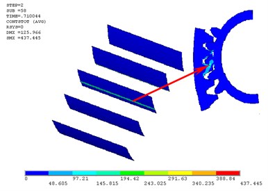
From Fig. 7 we can see that there are two critical meshing positions with ultimate contact stresses. The first one appears to be the worst contact position between the sun gear and the planetary gear where their contact state transfers from multi-tooth contact to single tooth contact (Fig. 8). The second meshing position with maximum contact stress appears to be the worst contact position between the gear ring and the planetary gear where the next pair of teeth is entering the engagement region and the last pair of teeth is leaving the engagement region (Fig. 9). The corresponding maximum contact stresses in the two worst positions are respectively 517.435 MPa and 437.445 MPa.
Fig. 8The first worst contact position
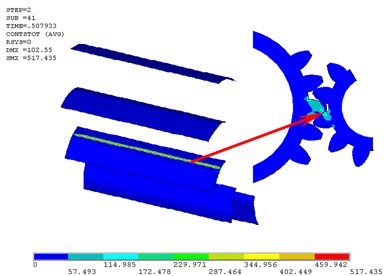
Fig. 9The second worst contact position
The root stress of the gear on the tensile side is usually the basis for calculating the bending fatigue strength of gear. For each gear in a planetary gear train there exists a position where the root stress achieves its maximum value. Fig. 10 shows the three time-history curves of root stresses of the sun gear, the planetary gear and the gear ring. The bending stress of each gear in any time can be extracted from the figure.
Fig. 10Time-history curves of root stresses
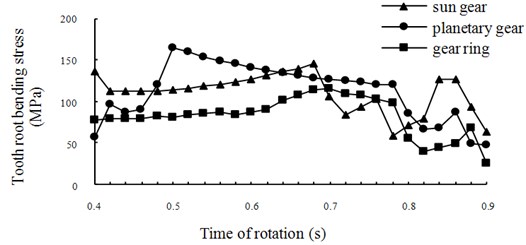
The bending fatigue life of the gear is determined primarily by the maximum root stress during the whole engagement period. Hence determination of the maximum root stress and the corresponding engagement position is the critical content of the dynamic analysis of the gear.
As shown in Fig. 10 the maximum root stresses of the sun gear and the planetary gear are respectively 517.435 MPa and 164.065 MPa, and the corresponding engagement positions are respectively the highest position of the single tooth engagement of the sun gear and of the planetary gear. The maximum root stress of the gear ring is 115.293 MPa. Similarly it is also located at the worst engagement position of the gear ring. For the gear ring its overlap ratio is always more than two, its worst engagement position lies at the boundary position where the gear ring transfers from three-tooth engagement to two-tooth engagement.
5. Conclusions
The nonlinear dynamic characters of the planetary gear train were analyzed and simulated. Based on the investigations, the following conclusions can be offered:
(1) During the engagement process of planetary gear train, both the contact stress of the tooth surface and root stress of the tooth root exhibit nonlinear transient behavior.
(2) There are two worst engagement positions where the contact stresses of the two gear pairs reach the maximum values. Meanwhile there are three worst engagement positions where the root stresses of the three gears respectively attain the maximum values.
(3) The time-history curves of the contact stresses between two contact pairs are independent and asynchronous. Similarly the time-history curves of the root stresses of sun gear, planetary gear and gear ring are also asynchronous. In order to ensure the strength requirement of the planetary gear train it is necessary to check the strength of the planetary gear train at all the five dangerous engagement positions.
References
-
Wang P., Cai X. Vibrational analysis of planetary gear trains by finite element method. Journal of Vibroengineering, Vol. 14, Issue 4, 2012, p. 1450-1458.
-
Meghdad K., Hojat A., Mahmoud O., Ashkan M. Vibration condition monitoring of planetary gears based on decision level data fusion using Dempster-Shafer theory of evidence. Journal of Vibroengineering, Vol. 14, Issue 2, 2012, p. 838-851.
-
Li C. Integration of finite element analysis and optimum design on gear systems. Finite Elements in Analysis and Design, Vol. 38, Issue 3, 2002, p. 179-192.
-
Vecchiato D. Tooth contact analysis of a misaligned isostatic planetary gear train. Mechanism and Machine Theory, Vol. 41, Issue 6, 2006, p. 617-631.
-
Satoshi O. Root stresses and bending fatigue breakage of planet gear. Bulletin of the JSME, Vol. 27, Issue 6, 1984, p. 995-1001.
-
Ishida T. Bending stress analysis of idle gear with thin rim. Bulletin of the JSME, Vol. 28, Issue 7, 1985, p. 1505-1511.
-
Sundararajan S., Amin S. Finite element analysis of ring gear casing spline contact. Journal of Propulsion and Power, Vol. 7, Issue 4, 1991, p. 602-606.
-
Duong L. Evaluation of ring gear tooth stress. American Society of Mechanical Engineers, Vol. 4, Issue 9, 2002, p. 363-369.
-
Ko K. E., Lim D. H., Kim P. Y., Park J. A study on the bending stress of the hollow sun gear in a planetary gear train. Journal of Mechanical Science and Technology, Vol. 24, Issue 1, 2010, p. 29-32.
-
Ignacio G. P., Jose L. I., Alfonso F. Implementation of Hertz theory and validation of a finite element model for stress analysis of gear drives with localized bearing contact. Mechanism and Machine Theory, Vol. 46, Issue 6, 2011, p. 765-783.
-
Hassan A. R., Thanigaiyarasu G., Ramamurti V. Effects of natural frequency and rotational speed on dynamic stress in spur gear. Engineering and Technology, Vol. 48, Issue 5, 2008, p. 448 – 455.
-
Hasanpour K., Ziaei Rad S., Mahzoon M. A large deformation framework for compressible viscoelastic materials: constitutive equations and finite element implementation. International Journal of Plasticity, Vol. 25, Issue 6, 2009, p. 1154-1176.
About this article

This work was supported by the Project for Scientific Development Plan of Shandong Province (No. 2011GGX10320), Doctoral Fund of Ministry of Education of P. R. China (No. 20113718110006), Shandong Provincial Natural Science Foundation of China (No. ZR2010EM013).
