Abstract
The paper presents the results of numerical modelling and experiments of piezoelectric bimorph-type bending actuator for laser beam shutting system. Theoretical calculations are realized by using finite element method. The purpose of these calculations is to optimize geometric parameters of a piezoelectric bimorph, ensuring maximum resonant frequency of the first bending form and stability of oscillation amplitude. Experimental performance of piezoelectric actuators is compared with results of finite element simulations.
1. Introduction
In this article we investigate a piezo-driven mechanical laser beam shutter, which can be used for modulation or the switching of the light intensity in various laser applications. Presently piezoelectric actuators are widely used in various mechatronic devices and systems, including high accuracy positioning systems, optical and laser scanning/deflecting devices, piezoelectric robots. Particular interest in using piezoelectric actuators was determined by their superior characteristics – high-energy efficiency and short response time. Piezoelectric actuators now belong to the most effective driving force or motion generation mechanisms; they operate both in quasi-static and resonance mode and in order to achieve the desired modal shape, it is necessary to optimize geometric parameters and obtain specific location of excitation zones. This fact is especially important for the ultrasonic transducers with several degrees of freedom [1-3].
The performance of piezoelectric devices strongly depends on the characteristics of the piezoelectric transducers, which are the main components of the piezomechanical system. The synthesis of specific oscillation areas of the piezoelectric actuator can be obtained by optimizing the geometrical parameters, the poling vector and the topology of excitation zones of the piezoelectric transducer. The piezoelectric effect plays an important role in the dynamical behaviour of these actuators [4]. So it is very important to know what modal shape will be excited when applying piezoelectric actuators for high resolution motion control [6].
Such piezoelectric bimorphs have very wide area of applications, such as sensor systems, printing technologies, scanners, ultrasonic atomizers, ultrasonic transducers, positioning transducers, viscosity measurement systems, flow measurement systems, energy harvesting, laser beam controlling systems, pneumatic valves for industrial and automotive applications, valves in medical applications, insulin pumps, braille keys for the blind, textile machinery, optical switches, oil exploration, machine and equipment monitoring, automotive engines, feedback sensors, high temperature accelerometers, rate & gyroscope sensors, intrusion alarms and many other devices. So development and investigations of such type piezoelectric actuators are very important.
2. The beam laser shutter design
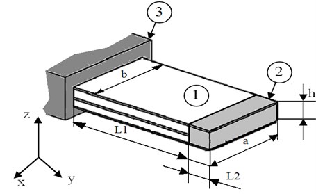
The important problem in designing laser devices is controlling the intensity of laser beam power up to zero, effected by various laser beam shutters for safety and beam control applications. Here are considered the specifics of bimorph type piezoelectric transducer, generating bending motion of the double layer piezoelectric element. Investigated piezoelectric laser beam shutter consists of the bimorph type piezoelectric actuator 1, special element 2 for shutting the laser beam and holder 3 of the piezoelectric actuator (see Fig. 1 a).
The model of a laser shutter is composed of two glued piezoelectric plates of rectangular shape, made of Pz26 piezoelectric material [5, 6]; the polarization vector is directed along the thickness of the plate. Seeking to cover laser beam, special element 2 is fixed at the tip of piezoelectric actuator 1.
Fig. 1The scheme of the laser shutter: a and b – width of the fixed and free ends of the plate respectively; h – height; L1 and L2 – lengths of the piezoceramic plate 1 and mass 2 respectively; 3 – holder
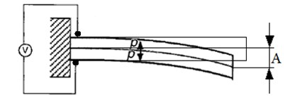
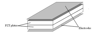
The piezoelectric elements are electrically connected in series as shown in Fig. 2, in which two piezoelectric elements with opposite poling directions are directly bonded. When an electric field is applied across the thickness in such a way that one piezoelectric element contracts while the other expands, the free end of the bimorph produces bending deformations of amplitude A. Bending deformations appears in actuator after bimorph is acted by voltage. Such electrodes placement is used for exciting the first bending mode in the piezoelectric actuator (Fig. 2).
Fig. 2Bending deformation of cantilever-mounted piezoelectric bimorph in series connection: P – poling vector; A – amplitude of the bending deformation
a)
b)
Geometric parameters of a piezoelectric bimorph have to be chosen in a way, ensuring the maximum of eigenfrequency of the first flexional mode and the stability of the oscillation amplitude . The geometrical parameters of piezoelectric actuators are shown in Table 1.
Table 1Geometric parameters of a bimorph
Piezoelectric material | PZ26 | ||
Width ratio | |||
Length , m | 0,050 | 0,050 | 0,050 |
Length , m | 0,005 | 0,005 | 0,005 |
Width , m | 0,01 | 0,01 | 0,01 |
Width , m | 0,01 | 0,005 | 0,0033 |
Height , m | 0,002 | 0,002 | 0,002 |
3. Modeling of bimorph
A harmonic analysis of the piezoelectric actuator was made by using finite element method and also with experiments. Finite element method was used to perform numerical modelling of the actuator. It was used to carry out modal frequency and harmonic response analysis and to calculate trajectories of the free tip movements of bimorph-type cantilever. Driving force of the piezoelectric actuator is obtained from piezoceramic plate. Finite element discretization of this element usually consists of a few layers of finite elements. Therefore nodes coupled with electrode layers have known potential values in advance and nodal potential of the remaining elements are calculated during the analysis. Dynamic equation of piezoelectric actuator is derived from the principle of minimum potential energy by means of variational functionals and in this case can be expressed as follows [7]:
where , , , , are matrices of mass, stiffness, electro elasticity, capacity, damping respectively; , {, are vectors of nodes displacements, potentials, structural mechanical forces and charge; , are accordingly vectors of nodal potentials known in advance and calculated during numerical simulation.
Natural frequencies and modal shapes of the actuator are derived from the modal solution of the piezoelectric system [7, 8]:
where is modified stiffness matrix and it depends on nodal potential values of the piezoelectric elements.
Harmonic response analysis of piezoelectric actuator is carried out applying sinusoidal varying voltage on electrodes of the piezoelectric elements. Structural mechanical loads are not used in our case, so . Equivalent mechanical forces are obtained, because of inverse piezoefect and can be calculated as follows [8]:
here , where is vector of voltage amplitudes, applied on the nodes coupled with electrodes.
Results of structural displacements of the piezoelectric actuator obtained from harmonic response analysis are used for determining the trajectory of tip movement.
For numerical analysis of piezoelectric actuators is used ANSYS software. The scheme for determining rational geometric parameters is shown in Fig. 3.
Geometric parameters of the piezoelectric actuator must be chosen in such way, that the resonant frequency should get the values as high as it possible, ensuring short response time. The resulting design would satisfy system‘s technical characteristics and be rational from a technological standpoint.
During analysis the dimensions of the free tip of piezoelectric bimorph-type cantilever have been changed (Table 1). In these bimorph models, it is imposed that one end of the cantilever is clamped in relation to mechanical boundary conditions. Hence, fixed constraint condition was applied for the vertical faces of the piezoelectric material layers. The other faces were unconstrained and free to move allowing the bending of the bimorphs under the application of voltage/force and due to the weight of the beam itself. The electroding of the top and bottom layers is required for the application of the voltage. However, the effects of the electrodes were not considered in the geometry because their mechanical behaviour can be neglected due to their thickness. The voltage of magnitude 19 volts is applied along the direction. For each considered case the harmonic analysis was performed (Fig. 5).
Fig. 3The scheme for determining rational geometric parameters
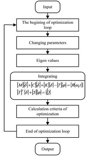
Fig. 4FEM models of piezoelectric actuators with ratio of parameters a and b: a) a = b, b) a = b / 2, c) a = b / 3
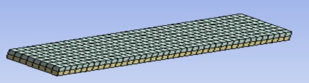
a)
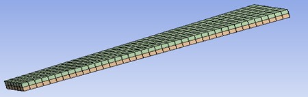
b)

c)
The largest bending displacements of the tip of piezoelectric actuator are in z direction. Calculated amplitude-frequency responses of piezoelectric actuators with different geometric parameters can be seen in Fig. 5. Theoretical results indicate, that the geometrical parameters of piezoelectric actuator have big influence for dynamic characteristics of it.
Fig. 5Amplitude-frequency responses of piezoelectric actuators with different geometric parameters (numerical simulation)
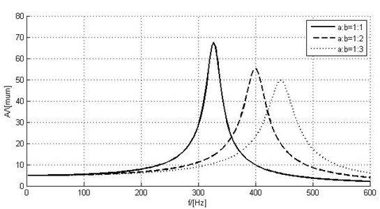
With bigger ratio of parameters and , the resonant amplitude gets smaller values, but resonant frequency increases: 68 µm, 320 Hz; 2 – 55 µm, 400 Hz; 3 – 50 µm, 440 Hz. The deformations of piezoelectric bimorphs are in Fig. 6.
Fig. 6Deformations of piezoelectric actuators, when ratio of parameters a and b: a) a=b, b) a=b/2, c) a=b/3
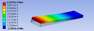
a)
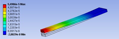
b)
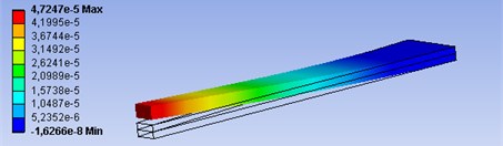
c)
4. Experimental results
The experimental setup is shown in Fig. 7 a). It consists of: 1 – power amplifier EPA-104; 2 – signal generator Agilent 33220A; 3 – analog digital converter (ADC) “PicoScope-3424”; 4 – laser displacement sensor LK-G82; 5 – laser sensor controller LK-G3001PV; 6 – Polytec OFV-5000 vibrometer controller; 7 – Polytec OFV-512 fiber interferometer; 8 – Polytec OFV-130-3 micro-spot sensor head; 9 – Polytec computer; 10 – computer; 11 – piezoelectric bimorph actuator. The piezoelectric actuators used in experiment are shown in Fig. 7 b). The dimensions of piezoelectric bimorphs are the same, as it is shown in Table 1.
Fig. 7Experimental setup a) and piezoelectric bimorph actuators used in experiments b)
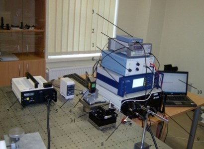
a)
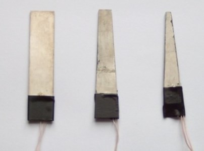
b)
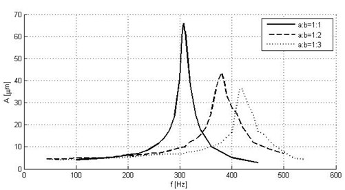
As a result of experiments we have amplitude-frequency responses that are shown in Fig. 9. Experimental results confirm the results of numerical modelling of piezoelectric bimorph actuator. With bigger ratio of parameters a and b, the resonant amplitude gets smaller values, but resonant frequency increases: 1 – 67 µm, 308 Hz, 2 – 44 µm, 384 Hz, 3 – 38 µm, 419 Hz.
Experimental results have confirmed, that the resonant frequency of the actuator depends on geometrical parameters of piezoelectric bimorph. The bending vibration resonant frequency of the cantilever increases approximately 1,3 times due to the decrease of the free end width of the cantilever by 3 times: that is from 308 Hz to 419 Hz.
The shutter presented in this article can also be used as a laser beam intensity modulator, optimized for the resonant mode of operation. Large amplitude sinusoidal modulation at the resonant frequency of the cantilever bimorph is generated, but additional air-cooling of the device must be provided, due to heating of the piezoelectric actuator.
Fig. 9Amplitude-frequency responses of piezoelectric actuators with different ratio of parameters a and b (experimental results)
5. Conclusions
According to numerical calculations and experimental results, the geometrical form of piezoelectric bending actuator, has big influence to its dynamic characteristics. With bigger ratio of , the resonant amplitude gets smaller values, but resonant frequency of the cantilever increases approximately 1,3 times due to the decrease of the free end width of the cantilever by 3 times: that is from 308 Hz to 419 Hz. Such optimization of geometrical parameters for piezoelectric bending actuators can be also used for piezoelectric laser beam intensity modulators.
References
-
Tzou H. S. Piezoelectric Shells (Distributed Sensing and Control of Continua). Kluwer Academic Publishers, 1993, p. 320.
-
Han J. M., Adriaens T. A., Koning W. L., Banning R. Modeling Piezoelectric Actuators. IEEE/ASME Transactions on Mechatronics, Vol. 5, No. 4, December 2000, p. 331.
-
Storck H., Wallaschek J. The effect of tangential elasticity of the contact layer between stator and rotor in travelling wave ultrasonic motors. International Journal of Non-Linear Mechanics, Vol. 38, 2003, p. 143-159.
-
Parashar S., Das Gupta A., Von Wagner U., Hagedorn P. Non-linear shear vibrations of piezoceramic actuators. International Journal of Non-Linear Mechanics, Vol. 40, 2005, p. 429-443.
-
Linnan Z., Zhi-Fei S. Analytical solution of a simply supported piezoelectric beam subjected to a uniformly distributed loading. Applied Mathematics and Mechanics, Vol. 24, No. 10, 2003, p. 1215-1224.
-
Liew K. M., He X. Q., Kitipornchai S. Finite element method for the feedback control of FGM shells in the frequency domain via piezoelectric sensors and actuators. Computer Methods in Applied Mechanics and Engineering, Vol. 193, Issue 3, 2004, p. 257-273.
-
Frangi A., Corigliano A., Binci M., Faure P. Finite element modelling of a rotating piezoelectric ultrasonic motor. Ultrasonics, Vol. 43, Issue 9, 2005, p. 747-755.
-
Sitti M., Campolo D., Yan J., Fearing R. Development of PZT and PZN-PT Based Unimorph Actuator for Micromechanical Flapping Mechanisms. Constant Magnet Motors, USA, 2001.
About this article

This work has been supported by Research Council of Lithuania, Project MIP-075/2012 and Project Go-Smart, VP1-3.1-ŠMM-08-K-01-015.
