Abstract
Minehunters are subjected to specific sea loads due to waving and dynamical impacts associated with underwater explosion. Sea waving can be sufficiently exactly modeled by means of statistical methods. Much more problems arise from modeling impacts due to underwater explosion. Knowledge of a character of impulse loading which affects ship shaft line can make it possible to identify potential failures by means of on-line vibration measuring systems. The problem of influence of sea mine explosion on hull structure is complex and belongs to more difficult issues of ship dynamics. Modeled signals and hull structure were recognized within sensitive symptoms of three sub models: model of hull structure, model of impact and model of propulsion system. All sub models allow testing forces and their responses in vibration spectrum using SIMULINK software and FEM models.
1. Introduction
Minehunters are subjected to specific sea loads due to waving and dynamical impacts associated with underwater explosion. Sea waving can be sufficiently exactly modeled by means of statistical methods. Much more problems arise from modeling impacts due to underwater explosion. Knowledge of a character of impulse loading which affects ship shaft line can make it possible to identify potential failures by means of on-line vibration measuring systems. The problem of influence of sea mine explosion on hull structure is complex and belongs to more difficult issues of ship dynamics. Underwater explosion is meant as a violent upset of balance of a given system due to detonation of explosives in water environment. A paper presents a proposal of identification of a degree of hazard the ship’s hull forced from underwater explosion. A theoretical analysis was made of influence of changes of hull structure in vicinity of hull. The main problem of naval vessels is a lack of dynamical requirements of stiffness of the hull. Modeled signals and hull structure were recognized within sensitive symptoms of three sub models: model of hull structure, model of impact and model of propulsion system. All sub models allow testing forces and their responses in vibration spectrum using SIMULINK software and FEM models.
2. Backgrounds of the underwater explosion
Knowledge of loads determined during simulative explosions is helpful in dimensioning ship’s hull scantlings [3]. Another issue is possible quantification of explosion energy as well as current potential hazard to whole ship and its moving system.
Underwater explosion is meant as a violent upset of balance of a given system due to detonation of explosives in water environment. The process is accompanied with emission of large quantity of energy within a short time, fast running chemical and physical reactions, emission of heat and gas products. The influence of underwater explosion does not constitute a single impulse [1] but a few (2 to 4) large energy pulsations of gas bubbles [2, 3, 5].
The period of each successive pulse gas bubble is different and depends on the depth of the epicenter of the explosion and mass of explosive material. According submerged cargo:
where – mass of TNT [kg], then gas bubble appears on the surface just after the first pulse. Regarding [3] period of the first pulse is:
The second period gas bubble pulsation has usually a range of 70-80 % of the first pulse period , while the third pulsation period is about 50 % of . The maximum radius of the gas bubble occurs during the first pulse. It is calculated by the following empirical formula [4]:
The empirical formulas consists maximum pressure , which Robert Cole described the following empirical equation:
where:
, – coefficients received through experiment;
– mass of TNT charge [kg];
– distance from detonation epicentre [m].
The maximum pressure is also important function describing the pressure change over time. Its course is approximated by an exponential function of the form:
where:
– time counted from the moment of first contact with the pressure wave [ms],
– time constant [ms].
3. Test study on the range maritime
To identify underwater explosion parameters a pilotage tests were performed with the use of the explosive charge having the TNT mass from 0.075 – 0.25 kg. The schematic diagrams of experiments are shown in Fig. 1 and Fig. 2.
The performed tests were aimed at achieving information dealing with:
• character of shock wave impact on shaft-line bearings, in the form of recorded vibration parameters;
• assessment of time-run of vibration accelerations with taking into account dynamic features of the signals in set measurement points;
• assessment of possible identification of influence of pulsation of successive gas bubbles during the time-run of vibration accelerations;
• identification of features of the signals by means of spectral analysis.
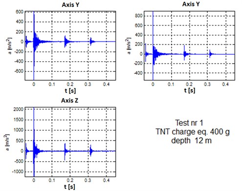
Three Bragg’s nets were used for the displacement of vibration measurements, subsequently identified: Strain1, Strain2 and Strain3 – Figure 3. Results of deformation caused by the underwater detonation are shown in Figure 4. The example of acceleration of boat’s hull during the explosion presents Figure 5.
Fig. 1Schematic layout of underwater detonation experiments
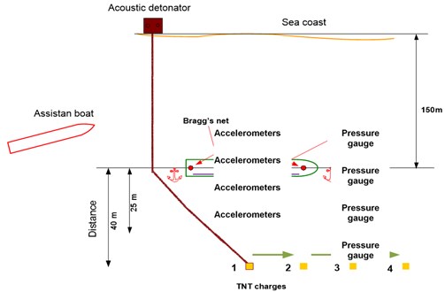
Fig. 2Distance and depth of TNT charges placement
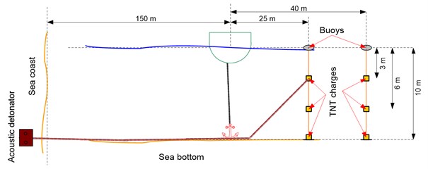
Fig. 3Scheme of fixing Bragg's nets inside the hull of assistant boat
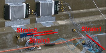
Fig. 4Example of the results of deformation caused by the underwater detonation measured by Bragg’s net
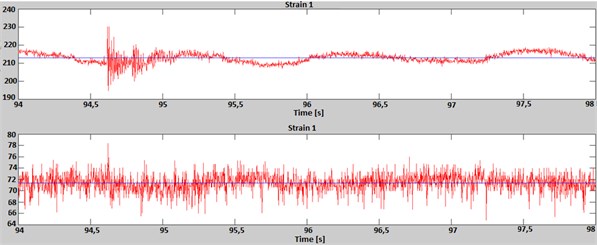
Fig. 5The example of acceleration of boat’s hull during the explosion
4. Model of excitation underwater explosion
Analysis of dynamic impacts including impulse ones should take into account basic parameters which influence character of time-run of a given signal as well as its spectrum [11, 12]. The basic parameters which identify impulse impact resulting from explosion are the following:
• form of impulse which identifies kind of impulse;
• impulse duration time at the ratio maintained constant, which identifies explosive charge power (time of propagation of gas bubble);
• influence of damping on spectrum form, which identifies distance from explosion and - simultaneously - epicentre depth;
• number of excitation impulses, which informs on distance from explosion, combined with explosive charge mass;
• time between successive impulses, which characterizes explosive charge mass [8, 12].
The possible recording of measured shock wave pressure and accelerations on intermediate and propeller shaft bearings enables to identify some explosion parameters hence also hazards to power transmission system.
Analysing the run of underwater shock wave pressure one is able to assume its time-dependent function:
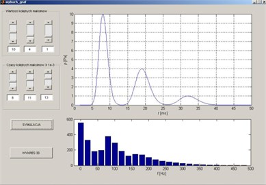
For the assumed mathematical model of the first shock wave impulse the run of vibration accelerations recorded on ship hull - for the example function given in Eq. (6) can be presented as shown in Fig. 6 and 7.
To achieve the proper shape of the values of must be greater than unity and the values of smaller than 0 (for given values of and adopted the values of , are obtained automatically correct values ) so [5]:
• the time of occurrence successive maxima functions;
• the amplitudes of successive maxima of the function ;
• the coefficients shape;
• simulation time ;
• time resolution .
Fig. 6Time waveform of modelled pressure
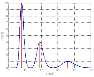
Fig. 7The Matlab window to calculate structure of the waves
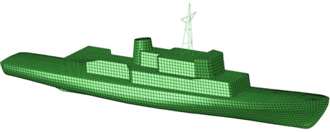
5. Spatial model of hull minehunter FM 206 type
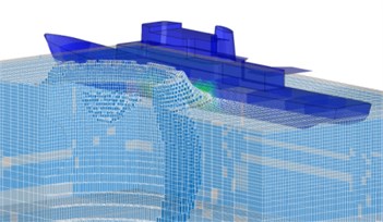
The minehunters of FM 206 type a.o. belong to the Polish Navy ships which are subjected to researches tests - Figure 8. Model hull is the result of analysis of the technical documentation and measurements made on real objects - minehunter. The mapped model of the 206FM type mine hunter was designed in the CAD geometry. This is the shell model made a significant simplification, without arms on-board equipment, frames, main compartments, etc. This model allows determining the pressure distribution of underwater detonation on the hull plate and determining the accelerations that are experienced by the external elements of the hull.
The geometry of the ship's hull was prepared using the formats for export and import of data transferred to the CAE, where there were 14 475 square discrete, coating components, coating 76 triangular elements, set in space by 11 753 nodes.
For the numerical simulation assumed elastic material model:
2.1e5 MPa;
0.3;
7850 kg/m3.
The introduction of centred masses in the model allows to get volume of hull displacement equal to 426 tons.
Fig. 8The structure of hull geometry of the minehunter 206FM type
6. The simulation results on the effects of underwater detonation of the ship hull
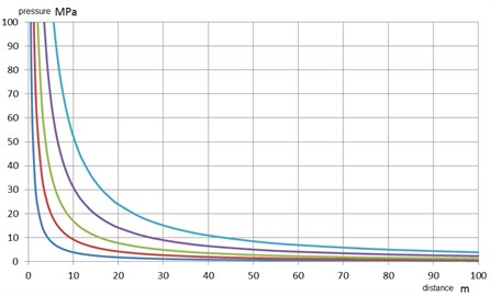
Characteristics presented on the Figure 9 shows simulation of the pressure at the front of detonation wave as a function of mass of the TNT load and distance from the epicenter, determined by the Cole’s formula.
Times that occur in the Cole’s formulas, and is counted from the time of the wave pressures at a given point of space, does not include conveyance from the epicenter [4, 12]. The pressure wave in the first phase of the explosion propagates at the speed of detonation of an estimated 5000 ÷ 8000 m/s. The velocity rapidly decreases to the velocity of sound in the medium [12].
Fig. 9Pressure values at the front of the shock wave as a function of load mass of TNT of 1, 10, 50, 250, 1000 kg
After taking into account velocity of propagation of pressure waves in water of 1500 m/s, the minehunter 206 FM type and TNT load equal mass 250 kg, exploded at a depth of 15 m with a distance of 20 m from the bow or the stern, the pressure wave reaches the maximum value of 11 MPa and decreases along the ship to the 3 MPa – Figure 10. The total time of occurrence the load on the structure of the ship is 0.0376 s.
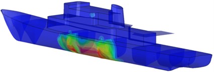
For the same TNT load, exploded at a depth of 15 m with a distance of 20 m on the beam, the maximum shock wave pressure reaches 11 MPa at amidships and decreases along the ship to the value of 5.9 MPa at the bow and stern. The total time of occurrence load on the hull of the ship is more than a half shorter and equal 0.0124 s. Distribution of pressure waves on the hull of the ship, coming from the TNT load exploded is presented on Figure 12.
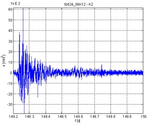
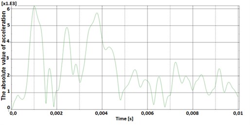
Pressure wave causes the hull load over its entire length. Figure 13, shows an example of the time course of the acceleration from the explosion of 250 kg TNT load at a distance of 20 m, at a depth of 15 m from the bow of the ship.
Fig. 10Pressure wave propagation along the length of the ship, detonation at a distance of 20 m before (behind) the ship at a depth of 15 m, mass of TNT load – 250 kg
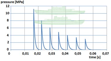
Fig. 11Pressure wave propagation along the length of the ship (from midship to the bow and stern), an explosion at a distance of 20 meters abeam of the ship, at a depth of 15 m, weight of TNT load – 250 kg
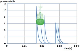
Fig. 12Distribution of shock wave on the hull coming from the TNT load explosion
a)
b)
Fig. 13Comparison between value of acceleration received from sea trial (left figure), a simulation (right figure, scale of acceleration is absolute) – the explosion front of the bow of the ship from a distance of 20 m, depth 15 m, TNT load mass 250 kg
a)
b)
7. Conclusions
Validation of presented model should in fact the implementation of a fully active experiment. This means the possibility of planning all important parameters of the experiment. These parameters are the mass of the charge, distance from the impact epicenter, the depth of detonation but also the nature of the bottom (different forms of seabed damping), the coefficient of reflectance of the sea surface and even the waves. Measured pressure during sea trials on real object (minehunter 206FM type) was made at a distance of 1 m from the side of the ship. Simulation results and the pressure determines the response of the ship forced by the impact pressure, just at the side of hull what was not measured. Presented results are only the effect of additive functions – modelled function and fit function. Measurement of the impact pressure could be carried out at the special research vessels or floating compartments where the pressure gauges are mounted just inside the vessels hull, below the waterline. Past performance are the result of the identification of the model involving the conjugate function of model and the nonliner coefficient of transition - fit function. These results are the identification of the model and not the full validation because of due to the possible of the experiment passive – active type. Identification model of charges for 4 detonation and 3 different distance from the epicenter indicates errors of RMS of acceleration from – 4 % to +13 % in the domain of time waveform in 3 points on the hull of the ship what was published by author in 2008 [6].
The results of testing allowed performing simulations of a similar nature to the actual loads of underwater explosions. Virtual model of the hull of the ship responds in a similar manner to the real impacts. Most simulations were performed to calculate or estimate the strength of the hull of plastic deformation. Load model of 2 or 3 bulbs allows assessing the potential occurrence of resonance at any point of the hull. This is important in the design process because the stiffness of the fixing or changing the mass of the foundation, can arrange the marine device from the potential risks coming from the resonance of an underwater explosion.
References
-
Borkowski W., Rybak P., Hryciów Z., Michałowski B. Multi-axle special-purpose vehicle in blast load conditions. Acta Mechanica et Automatica, Vol. 1, No. 2, 2007.
-
Brett J. M. Numerical Modelling of Shock Wave and Pressure Pulse Generation by Underwater Explosion. DSTO Aeronautical and Marine Research Laboratory, P. O. Box 4331, Melbourne, Australia.
-
Cole R. H. Underwater Explosions. Princeton University Press, Princeton, 1948.
-
Cudny K., Powierża Z. Selected Problems of Shock Resistance of Ships. Publishing House of Polish Naval University, Gdynia, 1987, (in Polish).
-
Dunbar T. E. Modelling of Close-Proximity Underwater Explosion Loads and Structural Response. Defence R&D, Canada – Atlantic, DRDC Atlantic CR 2008-272, 2009.
-
Grządziela A. Effects of underwater explosion on minehunters shaftline. Journal of Polish CIMAC, Vol. 3, No. 2, 2008, p. 55-64.
-
Hans U. Mair preliminary compilation of underwater explosion benchmarks. Proceedings of the 67th Shock and Vibration Symposium, SAVIAC, Volume 1, 1996, p. 361-379.
-
Huang Hao, Jiao Qing Jie Numerical modelling of underwater explosion by 1-dimensional ANSYS-AUTODYN. Workshop on Energetics – Past and Present, 7-9 December 2010, Hong Kong, China.
-
Lits M. B., Liu G. R. Comparative study of the real and artificial detonation models in underwater explosion simulations. Electron. Modelling, ISSN 0204-3572, Vol. 25, Number 2, 2003.
-
Zarrini M., Pralhad R. N. Estimation of shock velocity and pressure of detonations and finding their flow parameters. World Academy of Science, Engineering and Technology, Vol. 68, 2010, p. 234-238.
-
Rarnajeyathilagam K., Vendhan C. P. Underwater explosion damage of ship hull panels. Defence Science Journal, Vol. 53, No. 4, 2003, p. 393-402.
-
Young S. Shin Ship shock modelling and simulation for far-field underwater explosion. Computers and Structures, Vol. 82, 2004, p. 2211-2219.
About this article

