Abstract
In the work, vortex generators as a small vibrating plates adjusted to a delta wing surface are used for boundary layer control (BLC). The vortex generators applied to produce aircraft moments and aerodynamic forces are proposed and tested. The BLC for delta wing micro aircraft is calculated numerically by using fluid-structure interactions. The Navier-Stokes equations and Shear Stress Transport (SST) model were used for numerical calculations. The flexible oscillating small plates driven by controlled piezo stacks and their influence on the air flow in the delta boundary layer are investigated. The amplitude of the piezo stack vortex generator and frequency measurements are presented.
1. Introduction
The concept of the boundary layer, introduced by Prandtl [23] in 1904s, enables a control of the layer attachment to a solid surface that prevents flow separation. Usually flow separation deteriorates some performances, i.e. decreases the aircraft lift and increases the drag force [2, 13, 28]. The separation of the boundary layer at the top surface of the wings restricts the maneuverability of an aircraft. The flow control by excitation introduced by Schubauer and Skramstad [25], which is one of the boundary layer control (BLC) methods, uses a micro flap vortex generators [9, 10, 21]. Many methods and actuators were developed for flow control by periodical excitation [3]. The periodic flow oscillation can be achieved by vibrating plates [9, 10, 21], speakers [20, 24], oscillatory valves [1], jets [8, 26], fliperons [20], piezo-based benders [27], etc. The survey of the BLC and historical basic principles are presented by Greenblatt and Wygnanski [3]. The principle of the excitation method is to control the flow of air over a body by imparting controlled periodic perturbations in a laminar boundary layer to trigger a known instability called the Tollmien-Schlichting waves. These waves are generated by the vortex generators. The vortex generators work by mixing a high-energy air from the free stream with the lower energy air from the boundary layer. Especially in micro aerial vehicles (MAVs) the control surfaces are too small to quickly produce the control moments. The advantages to perform this excitation technique in controlling of the aircraft are as follows [3, 4, 10, 22]:
• the turbulence flow (higher energy fluid) is more resistive to separation,
• the critical angle of attack and lift force are increased,
• the flow energy is recovered and kept moving in the desired direction,
• the mean streamwise momentum of the boundary layer is increased by drawing in a high-momentum fluid form the free stream (this process is called reenergizing the boundary layer),
• the vortex generators are a small plates (very often based on MEMS technology [5-7, 12]) and adjusted to wing surface,
• the miniature vortex generator arrays increase the lift force by 10 % or more,
• the vortex generators increase the maneuverability of the aircraft, the aircraft is more robust to disturbances and it is more reliable.
The MAVs present many difficulties in the testing, control and fabrication processes. The major difficulties include low Reynolds number flows (104-105 or lower), low airspeed (10 – 20 m/s), fluid-structure interaction and small area of the wing [19]. The viscosity forces have a big influence on the low airspeed aerodynamics. Moreover, in the MAVs the interaction between unsteady aerodynamics and structural flexibilty is critical. From the control point of view, unsteady flow effect in the small scale MAVs with very low wing loading and almost nonexistent inertia cause problems in stability and maneuverability [16, 17]. The small oscillating plates, called smart control surfaces, adjusted in the MAV wing surface are unable to produce enough dynamic moments to maneuvering aircraft in the urban environment. When the MAV flies at high angle of attack, the airflow over the wing could stop following the shape of the wing, and consequently a lift produced by the wing could suddenly decrease. The effect of dynamic stall can be controlled by excitation of oscillating small parts adjusted in airfoil. The vortex generators as additional actuators can be connected to autopilot electronics of the external waypoints of the control system.
The paper presents the vortex generators assembled in the MAV based on the delta wing as a small vibrating plates controlled by the electronic drive. The main purpose of these vortex generators is to robustly control the MAV dynamics. In the paper, the three-dimensional numerical simulations of the boundary layer controlled by the two vortex piezo-generators (piezo stacks) assembled symmetrically in the delta surface are performed. The visual study of the flow separation over the BELL540 [32] airfoil and the set of two vibrating plate vortex generators to produce extra vortex and re-attach the separation flow are described. The fluid-structure interaction of the oscillating small plates and airflow dynamics are used to compute the aerodynamic forces and moments. Also, the meshing process and flexible dynamics of the piezo-generator moving surfaces are conducted. The efficiency of prevention of the flow separation depends on amplitude and frequency of the oscillating plates. It has been shown in the paper that the optimal amplitude and frequency of vortex generators operation is difficult to obtain. The each of vortex generators used in this study is a flexible plastic plate hinged at one end. The piezo stack is used as the actuator powered by linear amplifier. The piezo stack with a lever can provide at maximum up to 1 mm displacement and it has a maximum block force of 39 N. The details of the vortex actuators are also presented.
2. Flow control by plate vibration
The vortex piezo-generator is the feedback-loop control actuator. This system enables generation of active aircraft forces and moments, i.e. roll, pitch and yaw. It has been shown that by using miniature vortex generator installed on the upper wing surface of the MAV, the lift force at high attack angle could be increased by 10 % [10]. The vortex piezo-generator works by mixing high-energy air from the free stream with the lower-energy air in the boundary layer. The vortex piezo-generator reenergizes the boundary layer by frequency change. This means that the mean stream-wise momentum of the boundary layer is increased by drawing in a high momentum fluid from the free stream. The vortex piezo-generator consists of a small thin oscillating plate driven by piezo-stack controlled by microcontroller (see Fig. 1). The vortex piezo-generator includes the piezo stack, small plate and electronic drive. The vibrating part of the vortex piezo-generator is a flexible polyethylene plate of the size 100/10/1 mm hinged at one end. The plate is connected with the piezo stack by the small level, thus the maximal displacement of the plate is equal to 1 mm. The plate modulus of elasticity is equal to 1.1∙109 Pa and density is 950 kg/m3. The piezo-stack type APA120S [31] enables force generation up to 39 N with the maximum frequency 500 Hz. The piezo-actuator is controlled by microcontroller with the linear amplifier (CAu10) [31]. More information about piezo-generator is collected in Tables 2 and 3.
Fig. 1Scheme of the actuator with the active control system
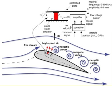
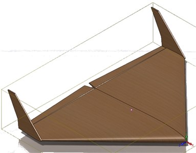
Fig. 2BULLIT 3D model
3. The BULLIT micro aerial vehicle
The micro air vehicle (MAV) examined in this paper is called BULLIT [33]. The single-delta wing profile is modification of NACA 0012 and is called BELL540 (see Fig. 2). The main MAV data are collected in Table 1. The control is accomplished using a set of aileron and elevator control surfaces. Thus, the airplane control system allows one to control the lateral-directional and longitudinal-directional dynamics. The full model has three control inputs: aileron, elevator and throttle.
Table 1BULLIT – selected parameters
Parameter | Nominal value | Parameter | Nominal value |
Name | BULLIT | Taper ratio | 0.236 |
Profile | BELL540 | Aspect ratio | 3.981 |
Total mass (ready to fly) | 1.27 [kg] | Wing span | 0.840 [m] |
Air speed | 15.00 [m/s] | Wing chord | 0.570 [m] |
Altitude | 100.00 [m] | Outer chord | 0.135 [m] |
Trim angle of attack | 0.087 [rad] | Area of the wing | 0.296 [m2] |
Trim sideslip angle | 0.00 [rad] | Area of the propeller | 0.033 [m2] |
Trim pitch angle | 0.00 [rad] | Taper ratio | 0.236 |
Inertia moments: ///// | 0.0184/0.0367/0.0550/ –0.00021/0/0 [kgm2] | MAC | 0.397 [m] |
Max. flight duration, at constant altitude of 100 m, and battery LiPo 2200 mAh | 0.60 [h] | Root-tip sweet | –8.927 [] |
4. Turbulence model
The laminar or turbulent airflow near the delta surface with the vortex piezo-generators is calculated by solving two-equation Navier-Stokes model. There are many models used in the prediction of turbulent flow calculations, where the standard - is the most popular because of robustness, economy, and reasonable accuracy for a wide range of flows [11]. However, the - model gives poor results of the non-equilibrium boundary layer calculations. The - model too late predicts the onset of the flow separation, which is important in simulation of nonlinear phenomena such as vortex creation and breakdown. To solve this problem the Shear Stress Transport (SST) model is used [15]. The model works by solving a turbulence/frequency-based model - at the wall and - in the bulk flow. A blending function ensures a smooth transition between the two models. The - model consists of two equations where first the continuity equation is as follows [15]:
where: – density, – vector of velocity.
The second equation is given by:
where: – sum of body forces, – effective viscosity accounting for turbulence, – modified pressure .
The values of and are calculated from the differential transport equation for the turbulence kinetic energy and turbulence dissipation rate [15]:
where: , , , – constant, , – constant.
The - solves two transport equations, where the first one is turbulent kinetic energy and the second one is turbulent frequency [15]:
where: 0.09, 5/9, 0.075, 2, 2.
The SST model is based on the - and - models given by equations (3-6) and is as follows [15]:
5. Delta wing meshing
The finite element model of the delta wing with two piezo-generators is designed by using ANSYS software [30]. The turbulence airflow is computed by solving 2- and 3- dimensional Navier-Stokes equations for the each tetrahedron and hexahedron of the delta grid model. To simplify the model only a half of delta wing was considered with symmetry plane boundary. The wind tunnel model was 6 times longer than the delta wing. The modelling of the turbulent airflow with low Reynolds number needs a high accuracy mesh. The tunnel-delta mesh 3D model consists of 2D regions such as: inlet, outlet, delta, moving flaps, free walls and symmetry.
In order to predict a flow near the wall, the thin inflation layers mesh model was used. The inflated boundary maximum thickness is equal to 160 mm, the inflated layers number is 10 and expansion factor is 1.2. The mesh structure near the delta in symmetry plane is shown in Fig. 3. In order to model the effects of fluid-solid interaction the face spacing mesh is used with edge length of 8 mm for delta (which means 2 % of the longer delta edge) and 20 mm for tunnel (which means 5 % of the longer tunnel edge). The default body spacing is 40 mm. The mesh statistics are that the total number of nodes is 85536, of tetrahedra 219470, of pyramids 565, of prisms 87049 and of elements 307084.
Fig. 3Inflation layers mesh, [18]
![Inflation layers mesh, [18]](https://static-01.extrica.com/articles/14428/14428-img3.jpg)
6. Transient flow simulation
For calculations using finite element method (FEM) some boundary conditions must be taken into account [29]. They are as follows:
• delta surface – wall without slip with symmetry plane,
• tunnel – inlet 15 m/s, outlet 0 Pa and free walls with free slip.
The initial conditions:
• initial pressure – 0 Pa,
• reference pressure – 1 atm,
• initial air speed 15 m/s,
• air model – ideal gas,
• air temperature – 25°C.
The air flow calculations are performed by using CFX package of ANSYS software [29, 30]. The calculations resolution is high because of fast changing of turbulence flow parameters such as viscosity, kinetic energy and turbulence energy. In order to interact the airflow near the delta surface with the solid-structure oscillating of vortex piezo-generator the fluid solid interaction interface (FSI) is used. The FSI is two-way coupled. It means, that plate deformations interact with airflow and vice versa. Thus, the flexible structural and fluid flow calculations are pending in parallel and results are exchanged in each time-step. The airflow investigations are performed for the delta wing with turned-on piezo-generators. The angle of attack and air speed are constant and equal respectively 15° and 15 m/s. For example, the velocity streamline plot for piezo-generators frequency at 20 Hz is presented in Fig. 4. Another energetic vortex caused by piezo-generators is clearly visible.
By using vortex piezo-generators the pressure distribution values above the delta wing are much lower (approximately 22 % lower) than in delta wing without piezo-generators (see Fig. 5).
Fig. 4Velocity streamline, excitation 20 Hz, [18]
![Velocity streamline, excitation 20 Hz, [18]](https://static-01.extrica.com/articles/14428/14428-img4.jpg)
Fig. 5Pressure distribution, excitation 20 Hz, [18]
![Pressure distribution, excitation 20 Hz, [18]](https://static-01.extrica.com/articles/14428/14428-img5.jpg)
7. Vortex piezo-generator
Vibrations of the small plate are generated by the multi-layer piezoelectric actuator (piezoelectric stack) type APA120S of CEDRAT TECHNOLOGIES [31]. This stack is a monolithic ceramic construction of many thin piezo-ceramic layers. These layers are connected electrically in parallel configuration. The piezoelectric stack (piezo stack) APA120S has high stroke and fast response. Its parameters are presented in Table 2.
The piezo stack is powered by miniature linear amplifier type CAu10 from CEDRAT TECHNOLOGIES [31], see Fig. 6. The amplifier for piezoelectric actuator is double-channel drive electronics. The CAu10 is dedicated to the supply of a piezoelectric actuator based on multi-layers piezoelectric ceramics such as APA120S. The drive electronics CAu10 includes DC/DC converter and two linear amplifiers dedicated to capacitive load allowing excitation of piezoelectric actuators between 5 and 150 V. For communication with an external controller the CAu10 has SPI bus. The control signals are filtered by the interpolation filters. The selected parameters of the CAu10 electronics are presented in Table 3.
The two plates were symmetrically fixed in delta wing (Fig. 7). The plate surface is equal to 0.0044 m2, the max. amplitude is 0.001 m and tested frequency equals from 10 to 300 Hz.
Table 2Piezo stack – selected parameters, [31]
Properties | Technical conditions/ description | Unit | Nominal values | Min. values | Max. values | |
Producer | CEDRAT TECHNOLOGIES | |||||
Type | Pass APA120S | |||||
Max. no load displacement | Quasistatic excitation, blocked-free | [μm] | 140 | 115 | 175 | |
Blocked force | Quasistatic excitation, blocked-free | [N] | 39 | 31 | 47 | |
Stiffness | Quasistatic excitation, blocked-free | [N/μm] | 0.28 | 0.22 | 0.31 | |
Resonance frequency (free-free) | Harmonic excitation, free-free, on the admittance curve | [Hz] | 7100 | 5680 | 8520 | |
Response time (free-free) | [ms] | 0.07 | 0.06 | 0.08 | ||
Resonance frequency (blocked-free) | Harmonic excitation, blocked-free, on the admittance curve | [Hz] | 1300 | 1105 | 1430 | |
Response time (blocked-free) | [ms] | 0.38 | 0.35 | 0.44 | ||
Height (in actuation direction) | [mm] | 13.00 | 12.80 | 13.20 | ||
Length | [mm] | 28.70 | 28.60 | 28.80 | ||
Width (incl. wedge & wires) | [mm] | 9.00 | 8.00 | 10.50 | ||
Mass | [g] | 7.20 | - | - | ||
Properties standard technical conditions of use and measurement | ||||||
Name | Definition | |||||
Free-free | The actuator is not fixed | |||||
Blocked-free | The actuator is fixed to a mechanical support assumed of infinite stiffness | |||||
Quasistatic excitation | AC voltage between -20 and 150 V at 1 Hz | |||||
Harmonic excitation | Voltage of 0.5 Vrms, sinusoidal mode from 0 to 100 kHz | |||||
Max. harmonic excitation | Voltage defined by the measurement of max. displacement, sinus at resonance frequency | |||||
Displacement measurement | Laser interferometer, capacitive displacement sensor | |||||
Admittance measurement | HP 4194 A electrical impedance analyser | |||||
Fig. 6The drive electronics and multi-layers piezoelectrics, [31]
![The drive electronics and multi-layers piezoelectrics, [31]](https://static-01.extrica.com/articles/14428/14428-img6.jpg)
8. Experimental tests of piezo-generators
The effect of periodic vibration of the plate was studied in the test rig. The measurements set-up for vortex generators testing is presented in Fig. 7. The vortex piezo-generators with the electronic drive and control unit are mounted in the delta wing. The piezo stacks are remotely controlled by 2.4 GHz Futaba radio system. The remote control receiver is mounted in the MAV. The measurements are focused on:
• obtaining the plate amplitude versus frequency,
• obtaining the maximal bandwidth of piezo stack,
• obtaining the optimal amplitude of the vibrating plate,
• checking relation between the remote control command signal and piezo stack frequency,
• verifying the excitation level for symmetrically adjusted vortex piezo-generators.
Table 3Linear amplifier – selected parameters, [31]
Properties | Technical conditions/ Description | Unit | Nominal values | Min. values | Max. values |
Producer | CEDRAT TECHNOLOGIES | ||||
Type | CAu10 | ||||
Main voltage | Standard main supply | [VDC] | 3.3 … 15 | - | - |
Control input voltage | Standard environment | [V] | 0 … 3.3 | - | - |
Min. output voltage | Standard environment | [V] | 5 | - | - |
Max. output voltage | Standard environment | [V] | 150 | 145.00 | 160.00 |
Gain | Standard environment | [V/V] | 45 | 42.80 | 47.30 |
Max. output current | [A] | 0.005 | 0.004 | 0.006 | |
Dimensions | [mm] | 27/25/7 | - | - | |
Mass | [g] | 2.2 | - | - | |
Properties of standard technical conditions of use and measurement | |||||
Name | Definition | ||||
Standard main supply | Main according to direction HD472, could be adapted to 110 VAC on request | ||||
Standard environment | Ambient temperature (15-25°C) and dry air (humidity < 50 % [rH]) | ||||
Fig. 7Piezo-generator measurements set-up
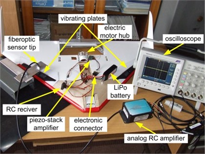
The amplitude is measured by fiberoptic displacement sensor (model RC62 of PHILTEC, Inc.) [32]. This sensor has reflectance compensated output, 2 mm operating range and 3mV/μ m sensitivity of measurement. The sensor is connected with the analog amplifier and ensures fast response (DC-20 KHz). The piezo stack frequency is measured by oscilloscope (Tektronix) for visualizing, analyzing and recording measured signals.
The selected plate vibration results are shown in Fig. 8. The amplitude range for all measurements was from 0.083 mm to 0.021 mm. The frequency range is tested from 10 to 300 Hz. It has been shown that by using miniature vortex generators, adjusted in the MAV wing surface, the lift force increases when the plate frequency is from 10 to 128 Hz [19]. When the frequency increases the amplitude decreases from 0.083 mm at 10 Hz to 0.023 mm at 200 Hz. The mechanical support of the piezo stack is assumed of infinite stiffness.
Fig. 8Frequency 10 Hz, amplitude 0.083 mm, [18]
![Frequency 10 Hz, amplitude 0.083 mm, [18]](https://static-01.extrica.com/articles/14428/14428-img8.jpg)
The piezo stack vortex generators extend the margin of aircraft stability. They can be used in the robust control feedback-loop system of the micro aircraft dynamics. Then, the future classification and model validation of the actuator is necessary [14, 16-19].
9. Conclusions
In this paper, the idea of applying the vibrating plates to vortex generation has been shown. The compressible Reynolds-averaged Navier–Stokes two-equations are solved to simulate the airflow over the delta wing with vortex piezo-generators at high angle of attack. The numerical results show that piezo-generators produce other vortices which cause decrease of the pressure above the delta wing and increase the lift force itself. The computational fluid dynamics (CFD) methodology based on the Shear Stress Transport (SST) turbulence model with the fluid-structure interactions is adopted. The simulations successfully capture the major features of the airflow around the delta wing with flight control by vortex piezo-generators. The experimental study of piezo stack vortex generators show that they can be used for controlling the flow of air over the delta wing by imparting periodic vibration to the flow.
It has been proved, that the performance of a micro aerial vehicle can be significantly enhanced by using vortex generation to prevent the flow separation.
The future investigations will concentrate on obtaining the optimal location and size of oscillating plates, the optimal operating frequency of vortex piezo-generators due to: velocity, angle of attack and other flight aerodynamics parameters.
References
-
Bachar T. Alternating Flow Generator. Patent Pending, 1998.
-
Chang P. K. Control of Separation. New York, McGraw-Hill, 1976.
-
Greenblatt D., Wygnanski I. J. The control of flow separation by periodic excitation. Progress in Aerospace Sciences, Vol. 36, 2000, p. 487-545.
-
Greenblatt D., Wygnanski I. J. Use of periodic excitation to enhance airflow performance at low Reynolds numbers. Journal of Aircraft, Vol. 38(1), 2001, p. 190-192.
-
Huang A., Folk C., Silva C., et al Applications of MEMS devices to delta wing aircraft: from concept development to transonic flight test. 39th AIAA Aerospace Sciences Meeting & Exhibit, Reno, Nevada, 01-0124, 8-11 January, 2001.
-
Huang A., Ho C. M., Jiang F., Tai Y. C. MEMS transducers for aerodynamics - a paradigm shift. 38th AIAA Aerospace Sciences Meeting & Exhibit, Reno, Nevada, 00-0249, Reno, Nevada, January, 2000.
-
Huang J. B., Jiang F. K., Tai Y. C., Ho C. M. A micro-electro-mechanical-system based thermal shear stress sensor with self-frequency compensation. Meas. Sci. Technol., Vol. 10, 1999, p. 687-696.
-
Johnston J. P., Nishi M. Vortex generator jets – means for flow separation control. AIAA Journal, Vol. 28, No. 6, June, 1990.
-
Kaiden T., Nakamura Y. Numerical analysis of aerodynamic control by micro-flap around delta wing. 19th AIAA Applied Aerodynamics Conference, Anaheim, California, 01-2441.
-
Kushari A. Boundary Layer Control Using Smart Materials. Research Project is funded by ADA under DISMAS scheme.
-
Launder B. E., Spalding D. B. The numerical computation of turbulent flows. Computer Methods in Applied Mechanics and Engineering, Vol. 3, 1974, p. 269-289.
-
Lee G. B., Chiang S., Tai Y. C., Tsao T., Ho C. M. Robust vortex control of a delta wing using distributed MEMS actuators. Journal of Aircraft, 2000.
-
Maskel E. C. Flow Separation in Three Dimensions. RAE Report Aero 2565, 1955.
-
Mehta M., Agrawal R., Rissanen J. SLIQ: a fast scalable classifier for data mining. Proc. of the 5th Int’l. Conf. on Extending Database Technology (EDBT), Avignon, France, March, 1996.
-
Menter F. R. Zonal two equation k-ω turbulence models for aerodynamic flows. AIAA Paper, 93-2906, 1993.
-
Mystkowski A. An application of mu-synthesis to control of a small air vehicle - simulation results. Journal of Vibroengineering, Vol. 14, Issue 1, 2012, p. 79-86.
-
Mystkowski A. The Robust Control of Unmanned Aerial Vehicle. Research Project report No. 0029/R/T00/2010/11 conducted in the years: 2010-2013, 2012, (in Polish).
-
Mystkowski A. Aerodynamics analysis of micro air vehicle (MAV) delta wing with controlled vortex piezo-generators. Acta Mechanica et Automatica, Vol. 4, No. 3, 2010.
-
Mystkowski A., Ostapkowicz P. Dynamics model verification of micro aerial vehicle with vortex piezo-generators. Warsaw Institute of Aviation, Z. 216, Warsaw, 2011, p. 103-125, (in Polish).
-
Nishri B. On the Dominant Mechanisms Governing Active Control of Separation. Ph. D. thesis, Tel Aviv University, 1995, (in Hebrew).
-
Polhamus E. C. Vortex Lift Research: Early Contributions and Some Current Challenges. Vortex Flow Aerodynamics, NASA CP2416, 1986, p. 1-30.
-
Polhamus E. C. Predictions of Vortex-Lift Characteristics by a Leading-Edge-Suction Analogy. Journal of Aircraft, Vol. 8, No. 4, 1971, p. 193-199.
-
Prandtl L. Über flüssigkeitsbeweung bei sehr kleiner-reibung. Proceedings of Third International Mathematical Congress, Heidelberg, 1904, p. 484-491.
-
Sathaye A. An acoustic vortex generator for micro-fluid particle entrapment. IEEE Ultrasonics Symposium, 2001.
-
Schubauer G. B., Skramstad H. K. Laminar Boundary Layer Oscillations and Transition on a Flat Plate. NACA Rep. 909, 1948.
-
Smith B. L., Glezer A. The formation and evolution of synthetic jets. Phys. Fluids, Vol. 10(9), 1998, p. 2289-97.
-
Seifert A., Eliahu S., Greenblatt D., Wygnanski I. Use of piezoelectric actuators for airfoil separation control. AIAA J., Vol. 36(8), 1998, p. 1535-7.
-
Telionis D. P. Review – unsteady boundary layers, separated and attached. ASME J. Fluids Eng., Vol. 101, 1979, p. 29-43.
-
Wilcox D. C. Turbulence Modelling for CFD. DCW Industries, La Canada, CA 91011, 2000, p. 314.
-
www.ansys.com
-
www.cedrat.com
-
www.philtec.com
-
www.topmodelcz.cz
About this article

The research work was financed with funds for Science as Research Project No O R00 0029 11 conducted in the years: 2010-2013.
