Abstract
Generalized flexibility matrix method has recently been introduced for identifying damages with the aim of overcoming some shortcomings of the approaches based on flexibility matrix. Researchers that use flexibility matrix to detect damages in structures face truncation errors ensue from cut off higher-order mode shapes, which are difficult to measure in practice. In this paper, a new procedure is presented to detect the damage site in a beam-type structure, where generalized flexibility matrix in conjunction with continuous wavelet transform (CWT) is utilized. Since flaws and cracks cause changes in flexibility of a system, this characteristic can be used as a damage indicator. Gaussian wavelet transform with four vanishing moments as a signal processing method is implemented to find the irregularity in a vector obtained from generalized flexibility matrix which is considered as a sign of damage. This method does not need to have either prior knowledge about the intact structure or its finite element model. The proposed technique is evaluated by numerical and experimental case studies.
1. Introduction
Presence of damage in engineering structures such as space vehicles and infrastructures may cause tragic, irreversible and monetary losses. Having been motivated by a desire to assess the influence of damages on structures, researchers have developed various damage detection techniques [1-3]. Vibration-based damage identification methods have been expanded as non-destructive techniques (NDTs) over the past three decades [4-9]. An extensive review of NDTs has been provided by Witherell [10].
Vibration-based methods are rooted in the fact that damages and flaws, which may ensue from anthropogenic or environmental loads, lead to change in the dynamic behavior of structures and therefore these dynamic characteristics can be used as practical tools in damage identification. Natural frequencies reduce due to the damages while damping ratio increases and, moreover, crack causes an abrupt irregularity in mode shapes of the structure. The location of a crack is determined by identifying this abnormality in the mode shapes or other quantities acquired from them such as stiffness matrix or flexibility matrix.
Use of spatial wavelet transform to localize damage in beam-type structures was firstly proposed by Liew and Wang [11]. Their work revealed the robustness of discrete wavelet transform compared to traditional eigenvalues based techniques. Hong et al [12] used a specific kind of continuous wavelet transform (CWT) called Mexican hat to discern the damage in a beam. Masoumi and Ashory [9] proposed a procedure to apply CWT on uniform load surface (ULS) and showed that using CWT in conjunction with ULS provides reliable and less prone to noise method for identifying damages in structures. They used ULSs obtained from noise free mode shapes and contaminated mode shapes to demonstrate the ability of the method in the front of noisy data. Furthermore, an experiment was performed on a cantilever beam to evaluate the applicability of the approach. Techniques based on wavelet transforms have been briefly reviewed by Masoumi and Ashory [13].
In this work, one of the vibration parameters, namely generalized flexibility matrix, which has recently been developed from flexibility matrix [14], is used to form a vector and then this vector is analyzed by Gaussian wavelet transform to find the location of damage in a beam-type structure.
2. Theoretical base of the procedure
Original flexibility matrix for a system with measured modes is obtained by [15]:
where , are th and th element of th mode shape and presents the th natural frequency. In order to decrease truncation error caused by cutting off the higher order modes, Li et al [14] proposed generalized flexibility matrix method. Generalized flexibility matrix is given by the expression [14]:
In Eq. (2) the power of natural frequency in denominator is twice the power of natural frequency in Eq. (1), therefore higher order modes, which are not measurable as easy as first three or four modes during modal testing, play less effective role and truncation error is more negligible.
CWT of space-domain signal is defined as:
In Eq. (3), is the complex conjugate of wavelet function and , are translation and scale parameters respectively. Any kind of function can be chosen as mother wavelet function provided that it fulfills the following condition:
where is the Fourier transform of . Furthermore, number of vanishing moments of a wavelet function is determined using:
Aside from boundaries, CWT with vanishing moments and small scale is equivalent to th derivative [16]. Although increasing the number of vanishing moments provides better outcomes, support length must be at least for a wavelet with vanishing moments and this extrapolation and expanding the support length causes flawed results. In this paper, a real wavelet called Gaussian wavelet with four vanishing moments is utilized, which is given by [16]:
Gentile and Messina [16] showed that Gaussian wavelets are able to provide essential information from a signal which corresponds to the respective derivatives. Furthermore, Rucka and Wilde showed that Gaussian wavelet is one of the most useful and practical wavelets to find singularities in displacement signals [17].
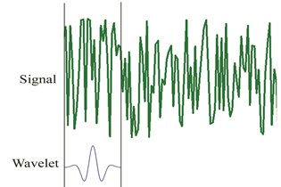
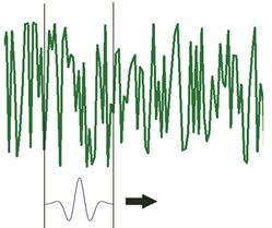
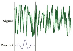
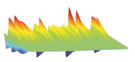
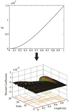
Fig. 1The procedure for computing wavelet coefficients
a)
b)
c)
d)
As presented in Fig. 1, to clarify how the wavelet coefficients are determined for a signal using Gaussian wavelet transform, five steps should be considered. First, Gaussian wavelet (Eq. (6)) is taken to compare it to the first part of the original signal (Fig. 1a). Then, for a specific scale and translation parameter the wavelet coefficient which shows the correlation of the wavelet with this section of the signal is calculated. Third, the wavelet is translated to the right and previous steps are repeated until computing all coefficients for the original signal (Fig. 1b). Next, the wavelet is scaled (Fig. 1c) and all previous steps are repeated. Finally, all steps are iterated to compute the wavelet coefficients for all scales. Obtained coefficients are used to plot a 3-D graph, which represents wavelet coefficients for all of the scales and translation parameters (Fig. 1d) [18].
3. Damage identification approach
In order to find the damage site, four steps are followed:
1. First two or three mode shapes of damaged beam are obtained. For experimental case these modes are acquired using ICATS software.
2. Generalized flexibility matrix is formed using Eq. (2).
3. For each degree of freedom , is defined as:
4. CWT is used to examine the vector to localize damage. Irregularity in this vector, which indicates the damage, is magnified by wavelet transform. By going from coarser scales to finer scales, we are able to find damage site at a specific fine scale. Using five steps procedure, described at the previous section, wavelet coefficients are calculated. These coefficients suddenly change when there is a singular point at which provides damage location.
4. Numerical analysis
As a numerical case, a cantilever beam of 1 m length is modeled by 60 elements having the same length in order to evaluate the proposed method. Nine damage scenarios are considered which are listed in Table 1. Damages are induced as reduction in Young’s modulus and mass matrix remains unchanged [19]:
where is the ratio of to , a is the depth of crack, is the height of the cross section area and corresponds to the half-width of the crack. Parameters are shown in Fig. 2.
Fig. 2Layout of the numerical case study [16]
![Layout of the numerical case study [16]](https://static-01.extrica.com/articles/14421/14421-img5.jpg)
Table 1Damage scenarios
Location (m) | (%) | Location (m) | (%) | Location (m) | (%) | |||
Case I | 0.2 | 20 | Case IV | 0.6 | 20 | Case VII | 0.9 | 20 |
Case II | 0.2 | 30 | Case V | 0.6 | 30 | Case VIII | 0.9 | 30 |
Case III | 0.2 | 40 | Case VI | 0.6 | 40 | Case IX | 0.9 | 40 |
As presented in Table 1, nine damage cases are considered and induced at different locations. For each damage case, reduction in frequency due to damage was calculated. These results along with natural frequencies obtained for first three modes are presented in Table 2.
When the damage is located near the clamped end (for cases I, II and III), reduction in frequency is more noticeable for the first and third natural frequency, while the second natural frequency experiences a small decrease. On the other hand, occurring damage at the locations near to the free end (for cases VII, VIII and IX) leads to inconspicuous changes in frequency for the first mode and, for these locations, most reduction is obtained in the third natural frequency.
Table 2Comparison of natural frequencies between intact beam and damaged beams
Frequency (Hz) | Mode I | Reduction | Mode II | Reduction | Mode III | Reduction |
Intact | 8.1538 | - | 51.0990 | - | 143.0788 | - |
Case I | 8.0829 | 0.0709 | 51.0976 | 0.0014 | 142.6227 | 0.4561 |
Case II | 8.0174 | 0.1364 | 51.0963 | 0.0027 | 142.2030 | 0.8758 |
Case III | 7.9732 | 0.1806 | 51.0955 | 0.0036 | 141.9210 | 1.1578 |
Case IV | 8.1458 | 0.0080 | 50.6828 | 0.4163 | 142.4963 | 0.5825 |
Case V | 8.1382 | 0.0156 | 50.2976 | 0.8015 | 141.9678 | 1.1110 |
Case VI | 8.1330 | 0.0208 | 50.0375 | 1.0616 | 141.6166 | 1.4622 |
Case VII | 8.1538 | 0.0001 | 51.0888 | 0.0102 | 142.9105 | 0.1683 |
Case VIII | 8.1537 | 0.0001 | 51.0792 | 0.0199 | 142.7499 | 0.3289 |
Case IX | 8.1537 | 0.0001 | 51.0725 | 0.0265 | 142.6388 | 0.4400 |
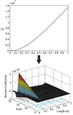
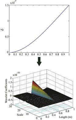
Finally when damages are located at the middle parts (for cases IV, V and VI), the largest reduction is observed in the second and third natural frequencies. For each location, an increase in damage severity results in a decrease in natural frequency compared to intact beam. First two mode shapes were utilized to form and then spline interpolation and extrapolation were used to obtain the refined grid points. Finally, Gaussian wavelet transform was implemented to localize abnormality in as a sign of damage. Figs. 3-5 show and obtained wavelet coefficients for all aforementioned damage cases.
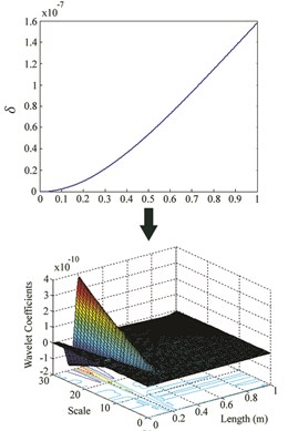
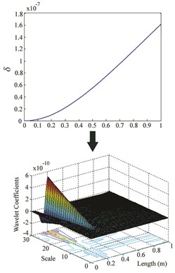
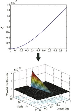
Fig. 3δ and wavelet coefficients for: a) Case I, b) Case II, c) Case III
a)
b)
c)
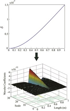
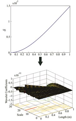
Fig. 4δ and wavelet coefficients for: a) Case IV, b) Case V, c) Case VI
a)
b)
c)
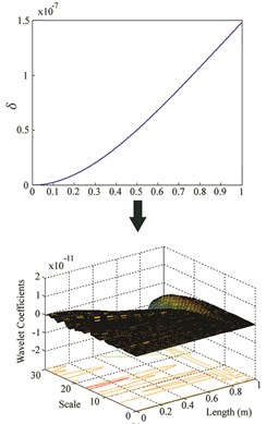
While the wavelet coefficients are nearly zero far from the damage site, they suddenly increase around the location of crack. Although there is no noticeable irregularity in at damage site, it can be observed that wavelet transform identifies damage location for cases I-VI. But when the damage is at the free end of the cantilever beam (for cases VII, VIII and IX), this method is unable to find the location. For each location, an increase in severity leads to an increase in the maximum wavelet coefficient which appears at damage site.
Fig. 5δ and wavelet coefficients for: a) Case VII, b) Case VIII, c) Case IX
a)
b)
c)
5. Experimental verification
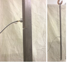
As depicted in Fig. 6(a), a free-free beam with a 40 % damage induced at 0.51 m from one end, was tested to verify the method experimentally. Dimensions of the beam were 0.94×0.05×0.01 m and it was excited using a hammer type BK8202 at 48 points and force signal was amplified by an amplifier type BK-2647A. An accelerometer type DJB-A/120 V was mounted at 0.48 m from one end.
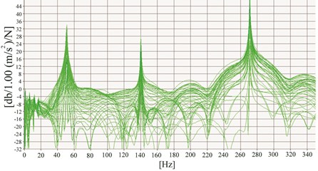
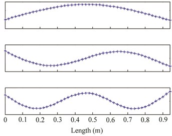
The sampling time is set to 488.3 µs. Responses and force signals were measured and frequency responses functions (FRFs) were extracted through Pulse software 8 [20]. These FRFs are shown in Fig. 6(b) for only first three natural frequencies. The Modent modulus of ICATS software [21] was used to obtain the first three mode shapes of the beam. These modes are given in Fig. 7(a).
Fig. 6a) Hammer modal testing on the free-free beam, b) FRFs from the hammer test
a)
b)
Generalized flexibility matrix and were formed based on Eq. (2) and Eq. (7) respectively. Spline interpolation and extrapolation were used to increase the number of grid points of and then Gaussian wavelet transform was applied on to find the damage location. Fig. 7(b) provides the obtained wavelet coefficients of for the damaged beam where maximum value of wavelet coefficients was obtained at the damage site.
Fig. 7a) First three mode shapes from hammer test, b) wavelet coefficients of δ for hammer test
a)
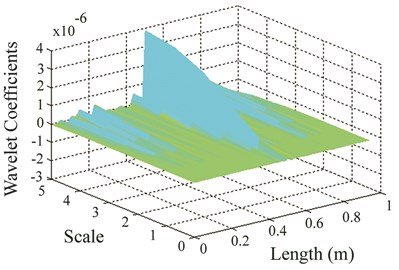
b)
6. Conclusions
In this work, a new approach based on generalized flexibility matrix was put forward to detect damage in beam-type structures and an experiment along with numerical simulations were performed to investigate the applicability of the proposed method. Gaussian wavelet transform was applied on a vector obtained from generalized flexibility matrix of damaged beam to discern the location of crack. This approach possesses the following advantages:
• Less number of modes is required to obtain accurate results in comparison to original flexibility technique, thanks to lower contribution of higher order modes.
• Not only prior knowledge of intact beam is not required but also there is no need to have numerical or finite element model of intact structure.
• This approach is relatively immune to noise due to the advantages of using wavelet transform.
References
-
Diamanti K., Soutis C., Hodgkinson J. M. Lamb waves for the non-destructive inspection of monolithic and sandwich composite beams. Composites: Part A, Vol. 36, Issue 2, 2005, p. 189-195.
-
Morassi A., Vestroni F. Dynamic Methods for Damage Detection in Structures: CISM Courses and Lectures. Italy: Springer, Wien, New York, 2008.
-
Li Y. Y. Hyper sensitivity of strain-based indicators for structural damage identification: a review. Mechanical Systems and Signal Processing, Vol. 24, Issue 3, 2010, p. 653-664.
-
Fan W., Qiao P. Vibration-based damage identification methods: a review and comparative study. Structural Health Monitoring, Vol. 10, Issue 6, 2011, p. 83-111.
-
Gu J. Z., Hao W. F., Luo Y., Tang C. Structural damage identification based on intrinsic mode function vibration transmissibility. Journal of Architecture and Civil Engineering, Vol. 28, Issue 1, 2011, p. 27-32.
-
Zhan J. W., Xia H., Chen S. Y., De Roeck G. Structural damage identification for railway bridges based on train-induced bridge responses and sensitivity analysis. Journal of Sound and Vibration, Vol. 330, Issue 4, 2011, p. 757-770.
-
Cao M., Lin Y., Zhou L., Su Z., Bai R. Sensitivity of fundamental mode shape and static deflection for damage identification in cantilever beams. Mechanical Systems and Signal Processing, Vol. 25, Issue 2, 2011, p. 630-643.
-
Banerjee S., Ricci F., Monaco E., Mal A. A wave propagation and vibration-based approach for damage identification in structural components. Journal of Sound and Vibration, Vol. 322, Issue 1-2, 2009, p. 167-183.
-
Masoumi M., Ashory M. R. Damage identification from flexibility matrix using wavelet transform. IMAC XXX A Conference and Exposition on Structural Dynamics, Jacksonville, Florida, USA, 2012.
-
Witherell C. E. Mechanical Failure Avoidance: Strategies and Techniques. New York: McGraw-Hill, 1994.
-
Liew K. M., Wang Q. Application of wavelet theory for crack identification in structures. Journal of Engineering Mechanics, Vol. 124, Issue 2, 1998, p. 152-158.
-
Hong J. C., Kim Y. Y., Lee H. C., Lee Y. W. Damage detection using the Lipschitz exponent estimated by the wavelet transform: applications to vibration modes of a beam. International Journal of Solids and Structures, Vol. 39, Issue 7, 2002, p. 1803-1816.
-
Masoumi M., Ashory M. R. Damage localization by wavelet analysis of uniform load surface. Journal of Vibroengineering, Vol. 14, Issue 1, 2012, p. 395-407.
-
Li J., Wu B., Zeng Q. C., Lim C. W. A generalized flexibility matrix based approach for structural damage detection. Journal of Sound and Vibration, Vol. 329, Issue 22, 2010, p. 4583-4587.
-
Berman A., Lannely W. G. Theory of incomplete models of dynamic structures. American Institute of Aeronautics and Astronautics Journal, Vol. 9, Issue 8, 1971, p. 1481-1487.
-
Gentile A., Messina A. On the continuous wavelet transforms applied to discrete vibrational data for detecting open cracks in damaged beams. International Journal of Solids and Structures, Vol. 40, Issue 2, 2003, p. 295-315.
-
Rucka M., Wilde K. Crack identification using wavelets on experimental static deflection profiles. Engineering Structures, Vol. 28, Issue 2, 2006, p. 279-288.
-
Zemmour A. I. The Hilbert-Huang Transform for Damage Detection in Plate Structures. University of Maryland, Faculty of the Graduate School, 2006.
-
Gentile A., Messina A. Detection of cracks by only measured mode shapes in damaged conditions. 3rd International Conference on Identification in Engineering Systems, Swansea, Wales, 2002.
-
PULSE. Version 8.0, Bruel & Kjær, Sound & Vibration Measurement A/S, 1996-2003.
-
MODENT. Integrated Software for Structural Dynamics, ICATS 1988-2000, Imperial College of Science, Technology and Medicine, University of London, UK.
About this article

This work is supported by the Talented Office of Semnan University.
