Abstract
Shaft cracks in a rotor system may lead to destructive failure, if not detected at right time. The transient vibrations of a rotor system with a transverse breathing crack during rotor shut-down has been analyzed using Finite Element Method (FEM) for flexural vibrations. Since the vibration signals during shut-down are non-stationary, continuous wavelet transform (CWT) has been used to extract the crack feature when the rotor is decelerating through critical speed during shut-down. A parametric study for different crack depths has been studied for different decelerations and it is found that CWT can be effectively used to detect the crack during rotor shut-down.
1. Introduction
Unbalance in a rotor-bearing system induces bending fatigue loads on the shaft, which may cause cracking of the shaft during operation. Timely detection of shaft cracks increases the reliability of the rotating machines which otherwise may lead to catastrophic failures. Detection and monitoring of fatigue cracks in a rotor-bearing system using vibration response is the subject of considerable interest since the past few decades [1, 2].
The earlier works mainly focused on the detection of cracks through steady state vibrations i.e. when the rotor is operating at constant speed. The vibration signals during machine startup or rundown are transient (frequency varies with time) in nature. Crack detection through transient vibration analysis is equally important especially for high speed machine which start and stop quite frequently such as aircraft engines.
Previous works [3-5] have been reported on the detection and monitoring of crack through transient vibration analysis while the rotor system is passing through the critical speed. However, these works were mainly focussed on using speed response, time domain signals and/or the traditional signal processing technique such as FFT for the analyses of detection of cracks during startup of the rotor system. Prabhakar et al. [6], successfully used the wavelet transform to detect the shaft cracks while the rotor-bearing system passes through the critical speed during start-up. Sekhar [7] extended the use of wavelet transform to detect crack during startup and shut-down of the rotor system mounted on the fluid film bearings. Crack features such as subcritical speed peaks may also be present due to oil whirl in the case of the rotor system supported on fluid film bearings under certain conditions.
Since the detection of shaft cracks using wavelet transforms when the rotor is decelerating through the critical speed are rarely found in literature especially when the rotor system is mounted on rolling element bearings, the present work has been considered to detect shaft crack during the rotor coast-down. Transient analysis of the rotor-bearing system with a transverse breathing crack has been studied by using finite element method (FEM) for flexural vibrations. Time responses and the corresponding wavelets transformed vibration signals have been analysed for different crack depths and for different decelerations of a rotor system during shut-down.
2. System equation of motion
The rotor-bearing system having discrete discs and bearings and a shaft with distributed mass and elasticity is considered in the present study. Dynamic modelling of the rotor-bearing system using finite elements developed by Nelson and McVaugh [8]and the extended model by Ozguven and Ozkan [9] have been used. Internal damping is neglected here.
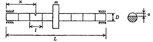
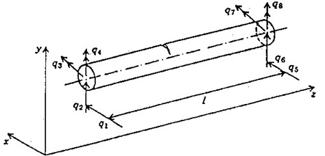
The rotor shaft is discretized into finite beam elements as shown in Figure 1. The beam element has two nodes and four degrees of freedom at each node represented by - for bending mode. Two translational degrees of freedom are represented by , , and and two rotational degrees of freedom are represented by , , and . Even though the element shown in Fig. 1. is a transverse cracked element, the degrees of freedom considered are the same for an uncracked element.
Fig. 1A rotor-bearing system with cracked element
a)
b)
The equation of motion of the complete rotor system in a fixed co-ordinate system can be written as:
The rotary and translational mass matrices of the shaft and the rigid disc mass, and the diametral moment of inertia are included in the mass matrix []. The matrix [] includes the gyroscopic moments and the bearing damping. The stiffness matrix comprises the stiffness of the shaft elements (cracked shaft element in the case of the cracked rotor) and the bearing stiffness. The details of mass, damping and stiffness matrices of Eq. (1), except for the cracked element, are given in references [8, 9].
The unbalance forces due to the disc having mass and eccentricity and the weight of the disc are included in the excitation matrix {} in Eq. (1) at appropriate degrees of freedom. The unbalance force components in x and y directions for angular rotation are given as:
3. Crack modeling
The effect of transverse breathing crack on the dynamics of the rotor-bearing system during shut-down has been considered in the present work. Papadopoulos and Dimarogonas [10] derived the flexibility matrices of the cracked element for flexural vibrations. These flexibility matrices are utilised in the present work as proposed in the FEM analysis of Sekhar and Prabhu [3].
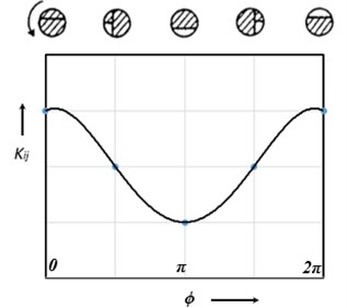
The phenomenon of the opening and closing of the crack during shaft rotation is called the breathing action of the crack. Papadopoulos and Dimarogonas [11] illustrated the breathing action of the crack, which is shown in the Fig. 2. The crack opens and closes depending on the rotor deflection. If the the static deflection is much higher than the rotor vibration which is the case for large class of machines, then the breathing action of the crack takes place. Considering this case, the crack closes when 0 and it fully opens when .
Fig. 2Breathing behaviour of the crack
A crack on the beam element (shown in Fig. 1) introduces considerable local flexibility due to strain energy concentration in the vicinity of the crack tip under load. The local flexibility due to the additional strain energy can be represented by a local flexibility matrix which will be and for a fully open crack and half-open, half-closed conditions respectively due to breathing phenomenon of the transverse crack.
The flexibilty matrices of cracked element such as [] and [] are computed from the derivations discussed in reference [10, 11]. The total flexibility matrix for the cracked section can be obtained by adding the additional flexibility matrix due to crack to the flexibility matrix, [], of the uncracked element, which is given as:
From the equilibrium condition:
where [] is the transformation matrix which is given in Ref [10].
The stiffness matrix of the cracked element is written as:
Stiffness matrix of the cracked element, [], replaces the stiffness matrix of the uncracked element, while assembling the stiffness matrix of the shaft, [] in the system equation of motion, Eq. (1).
The stiffness variation during the rotation due to crack breathing may be expressed as a function of time or angle, by a truncated cosine series [11]:
where [], 0, 1, …, 4, are fitting coefficient matrices. [] can be derived from the known behavior of the stiffness matrix at certain angular locations as explained by Papadopoulos and Dimarogonas [11].
4. Continuous wavelet transform
Vibration signal during start-up or shut-down are non-stationary in nature, which means the frequency changes with time. The traditional signal processing technique, Fast Fourier Transform (FFT) assumes the signal is stationary and gives the frequency content of the signal which prevails over the entire duration of the signal. This property makes the Fourier transform unsuitable for analysing the nonstationary vibration signal. Whereas the wavelet transform breaks the signal into its scaled shifted versions of the mother wavelet and hence provides the time-frequency information of a signal, enabling the extraction of features that vary in time. This property of wavelets has been used in the present study to analyze transient or nonstationary signals and also to extract crack features while the rotor-bearing system decelerating through the critical speed during shut-down.
The continuous wavelet transform (CWT) of a time signal can be defined as the sum over all time of the signal multiplied by scaled, shifted versions of the wavelet function . Mathematically:
where denotes the mother wavelet. The parameters and represent the scale index which is reciprocal of frequency and the time shifting (or translation).
5. Results and discussion
A Jeffcott rotor having a transverse breathing crack has been considered for the analysis. Data used for rotor system: 7800 kg /m3; density = 2.08×10¹¹ N/m2; shaft diameter 20 mm, length 500 mm; = 0.45; disc mass 5.5 kg, 0.01 mm, 0.01546 kg m2; bearing stiffness = 105 N/m, damping = 100 Ns/m. The first critical speed of the uncracked rotor system is 1456.2 RPM (152.4 rad/sec). The Houbolt time marching scheme with a time step of 0.001 second is used to simulate the time response from the system equation of motion of the rotor system. Morlet wavelet having a support length of (–4, +4) is used in analysis to analyse the vibration signal during rotor shut-down. Crack depth is defined as .
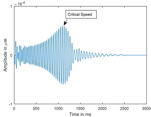
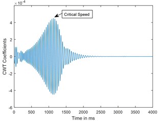
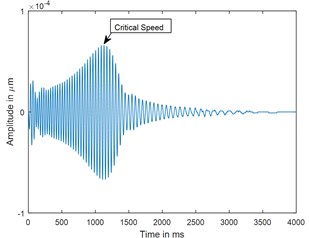
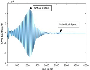
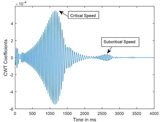
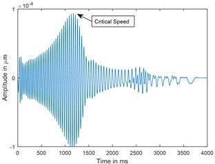
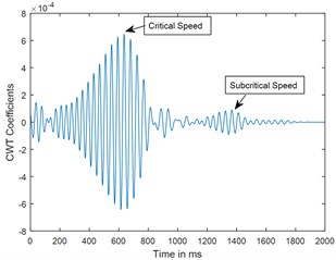
Dynamic response of rotor system when the rotor shuts-down at a speed of 225 rad/s (2148.6 RPM) and decelerates to rest with a deceleration of –75 rad/s2 is plotted in the Figs. 3 and 4. Time responses of uncracked and cracked rotor system are shown in the Figs. 3(a) and 4(a). The critical speed peak around 1.1 sec which corresponds to 152.4 rad/sec (24.27 Hz) is evident from the time response. The amplitude of vibrations rises when the crack is present in the rotor system, however there are no clear symptoms of crack features such as subcritical speeds noticeable from the time responses. The time signals are converted to one dimensional wavelet domain using Morlet wavelet having a scale of 35 and are plotted in the Figs. 3(b) and 4(b). Fig. 3(b) shows a peak at critical speed when the uncracked rotor is decelerating through the critical speed. However, from the CWT coefficient plot of a cracked rotor (please refer Fig. 4(b)), it is evident that besides the rise in vibration amplitude and critical speed peak, a crack feature viz subcritical speed peak at half the critical speed is present. Using time frequency and multi resolution capability of the wavelet transform, the embedded feature of the crack in the time response can be extracted and based on the time localisation in the wavelet domain the peak can be identified as sub-critical speed. Since the vibrations during machine shut-down are transient in nature, CWT can be used as an effective tool to detect the crack.
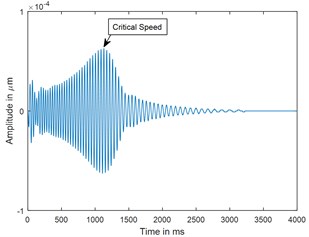
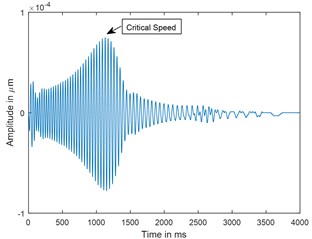
A parametric study has been carried out to investigate the sensitivity of crack depth and also to study the effect of decelerations on detection of shaft crack. Time response and the corresponding CWT plots for different crack depths when the rotor shuts-down at a speed of 200 rad/s and decelerates to rest with a deceleration of –50 rad/s2 is plotted in the Figs. 5-7. Increase in vibration amplitudes with the increase in crack depths are observed from both the time and CWT plots. Subcritical speed is noticeable in the CWT plot only (not from time response plots) when the crack depth reaches 0.2. Hence further analysis is required to detect the cracks below 0.2. CWT is found more powerful to detect the shaft cracks when the rotor is coming to rest with high deceleration. This is demonstrated in the Figs. 8, 9 and 4. When the rotor is decelerating to rest with low deceleration for example 50 rad/s2 (please refer Fig. 8), the subcritical speed is also noticeable, however not clear in the time response. Whereas when the rotor is decelerating to rest with high deceleration (100 rad/s2), the crack feature embedded in the time response which can be seen from the Fig. 9(a) and the crack feature viz subcritical speed can be extracted through wavelets as shown in the Fig. 9(b). Based on the transient analysis of vibration response during rotor shut-down, thus, CWT can be used as an effective tool to detect the shaft crack.
Fig. 3Time response and corresponding CWT plots of uncracked rotor, α- = 0; when rotor is decelerating at –75 rad/s2; X/L= 0.45
a) Time
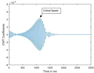
b) CWT
Fig. 4Time response and corresponding CWT plots of cracked rotor, α- = 0.4; when rotor is decelerating at –75 rad/s2; X/L= 0.45
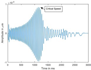
a) Time
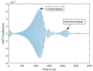
b) CWT
Fig. 5Time response and corresponding CWT plots of uncracked rotor, α-= 0; when rotor is decelerating at –50 rad/s2; X/L = 0.45
a) Time
b) CWT
Fig. 6Time response and corresponding CWT plots of cracked rotor, α-= 0.2; when rotor is decelerating at –50 rad/s2; X/L = 0.45
a) Time
b) CWT
Fig. 7Time response and corresponding CWT plots of cracked rotor, α-= 0.3; when rotor is decelerating at –50 rad/s2; X/L = 0.45
a) Time
b) CWT
Fig. 8Time response and corresponding CWT plots for deceleration θ¨= –50 rad/s2; X/L = 0.45; α-= 0.4
a) Time
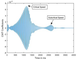
b) CWT
Fig. 9Time response and corresponding CWT plots for decelerations θ¨= –100 rad/s2; X/L = 0.45; α-= 0.4
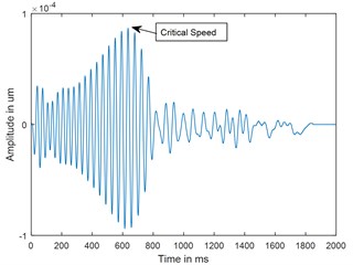
c) Time
d) CWT
6. Conclusions
Vibration analysis of rotor-bearing system during shut-down has been studied by using finite element method (FEM) for flexural vibrations to detect a shaft crack. The subcritical speed peaks are extracted by using CWT when the cracked rotor is passing through its critical speed. These peaks are not apparent in time response. CWT is more powerful for detecting cracks at high accelerations compared to time response, however for crack depths below 0.2, further analysis is required to detect the shaft cracks. The amplitudes of vibration at critical and sub critical speeds increase with the increase in crack depths.
The results suggest that CWT can be used for crack detection and monitoring when the rotor is decelerating through the critical speed during shut-down.
References
-
Waur J. Dynamics of cracked rotors, literature survey. Applied Mechanics Reviews, Vol. 43, 1990, p. 13-17.
-
Gaush R. A survey of the dynamic behavior of simple rotating shaft with a transverse crack. Journal of Sound and Vibration, Vol. 160, 1993, p. 313-332.
-
Sekhar A. S., Prabhu B. S. Transient analysis of a cracked rotor passing through the critical speed. Journal of Sound and Vibration, Vol. 173, 1994, p. 415-421.
-
Plaut R. H., Andruet R. H., Suherman S. Behavior of cracked rotating shaft during passage through a critical speed. Journal of Sound and Vibration, Vol. 173, 1994, p. 577-589.
-
Darpe A. K., Gupta K., Chawla A. Transient response and breathing behavior of a cracked Jeffcott rotor. Journal of Sound and Vibration, Vol. 272, 2004, p. 207-243.
-
Prabhakar S., Sekhar A. S., Mohanty A. R. Detection and monitoring of cracks in rotor bearing system using wavelet transforms. Journal of Mechanical Systems and Signal Processing, Vol. 15, 2001, p. 447-450.
-
Sekhar A. S. Crack detection and monitoring in a rotor supported on fluid film bearings: start-up versus run-down. Journal of Mechanical Systems and Signal Processing, Vol. 17, 2003, p. 897-901.
-
Nelson H. D., McVaugh J. M. The Dynamics of Rotor-Bearing Systems using Finite elements. ASME Journal of Engineering for Industry, Vol. 98, 1976, p. 593-600.
-
Ozguven H. N., Ozkan J. L. Whirl speeds and unbalance response of Multi bearing rotor using finite elements. ASME Journal of Vibration, Acoustics Stress and Reliability in Design, Vol. 106, 1984, p. 72-79.
-
Papadopoulos C. A., Dimarogonas A. D. Coupled longitudinal and bending vibrations with an open crack. Journal Sound and Vibration, Vol. 117, 1987, p. 81-93.
-
Papadopoulos C. A., Dimarogonas A. D. Stabililty of cracked rotors in the coupled vibration mode. ASME Journal of Vibration, Acoustics and Reliability in Design, Vol. 110, 1988, p. 356-359.
About this article

