Abstract
Pipe holders are the integral part of every pipeline and plays important role in vibration propagation and absorption in the pipes. Evaluation of mathematical model and parameter identification of clamping element are shown in this paper. Derived mathematical model provides good vibrational behavior approximation of real clamp thus allowing using it in various engineering calculations.
1. Introduction
Pipelines are one of the main means for transporting gases, liquids, various waists and other substances over long ranges not only in industrial environments but also in houses, hotels, and other public and private places in close proximity of humans. Not surprisingly these pipes' nets have a side effect of acoustic noise pollution. While standards regulating noise pollution in living and industrial areas become more strict design of piping system must be more sophisticated to satisfy new noise pollution rules.
Pipe clamping elements are an integral part of every pipeline thus have undisputed influence to acoustic noise (sound) propagation. In this paper new method for evaluating pipe holder vibro acoustic characteristics in low frequency range will be shown.
2. Problem
In many real world piping installation pipes can be considered as sources of acoustic noise / vibration. In this perspective pipe holders are the main elements which physically interacts with the vibration source and transfers these oscillations from the pipe to the wall or other support constructions. Successful noise and vibration reduction in the pipelines can be done only by fully understanding how all integral parts (including pipe holders) of the pipeline work.
There are many scientific papers or doctoral thesis which deals with problems associated with measuring, modeling and estimating of pipes' vibrations [1, 2, 3]. Only few of them touches pipe holders but does not investigates them too closely [4].
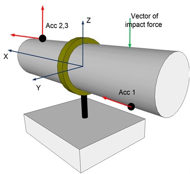
Despite this lack of attention pipe clamping element influence to the vibration propagation from the pipe to the construction supporting the pipeline cannot be neglected. In papers [5, 6] can be found two different methods to evaluate pipe holder vibro-insulation parameters. Methods described in these two papers have one major drawback – the pipe holder is investigated only in one ZX plane as shown in Fig. 1.
Fig. 1A schematic diagram of pipe imitator with the pipe holder
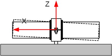
To address this issue two new pipe holder models will be proposed, which together are capable to reproduce low frequency pipe holder vibration behavior in three planes XZ, XY and YZ.
3. The model
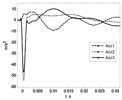
There are many types of pipe holders but this paper will concentrate on most common of them: two half rings with rubber inlay between rings and the pipe for better vibration absorption. Assuming that the holder model should describe low frequency vibration behavior of the pipe segment clamped with pipe holder (low frequency range is chosen because in this pipe holder's influence to the pipe vibrations are most noticeable), actual pipe was replaced with the pipe imitator. Imitator was chosen in a way that in the frequency range of interest (0-600 Hz) it vibrates as single mass (no modal vibrations). This replacement is perfectly valid because the real pipe in close proximity from the pipe holder behaves exactly the same [4]. Vibrational behavior of the imitator-holder system was evaluated by exciting different vibrations of the imitator and sensing those vibrations with the several accelerometers placed on different locations as shown in Fig. 2. Sensed accelerations for this particular setup are shown in Fig. 3.
Fig. 2Sensors locations (black dots) and impact point and direction of an excitation hummer are shown on the imitator-holder system. Arrows near the sensors show directions of positive signal sensing
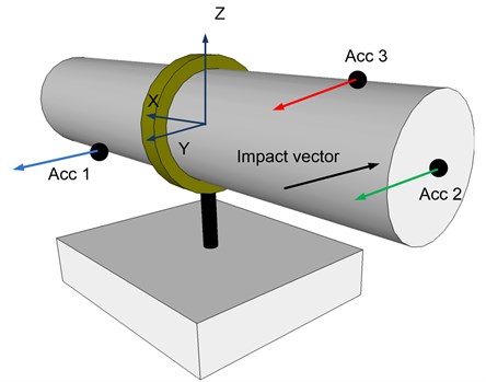
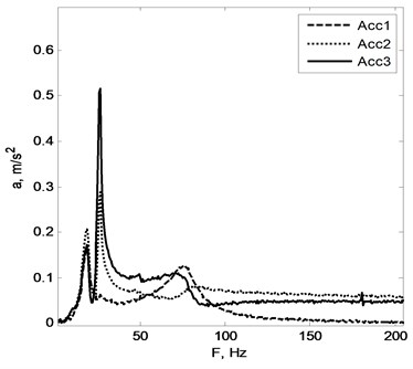
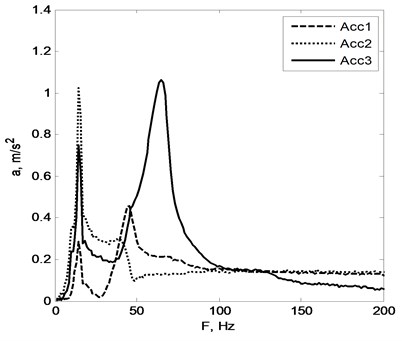
Fig. 3a) accelerations, b) acceleration spectrum sensed by the sensors
a)
b)
First spectral peak found near 20 Hz frequency mark (see Fig. 3(b)) corresponds to pipe imitator vibration around Z axis. Accelerometers number one and three were placed at the same distance from the axis of rotation (Z) and accelerometer number two a bit further. That is why spectral peaks near 20 Hz have the same amplitude for the sensors number 1 and number 3. Sensor number 2 sensed a bit higher level of acceleration (because of the longer mounting distance from Z axis). Next spectral peak around 30 Hz mark corresponds to the swing of the whole system around axis parallel to the X axis of defined coordinate system. The third peak (80 Hz) is a result of the pipe imitator vibration inside the ring of the holder.
By applying excitation along Z axis and measuring vibrations at point shown in Fig. 4 was possible to evaluate how system pipe imitator-holder vibrates in XZ plane.
Fig. 4Accelerometers location and resulting vibration spectrum of setup number 2. Arrows near the sensors show directions of positive signal sensing
a)
b)
System vibration decomposition to separate components is possible by analyzing acceleration spectrums shown in Fig. 4 part B. Peak near 20 Hz mark is consequence of the whole system vibration around the axis parallel to the Y axis of the coordinate system, 50 Hz peak is due to pipe imitator vibration around Y axis inside the holder ring and 70 Hz peak corresponds to the linear vibration along Z axis.
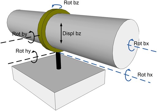
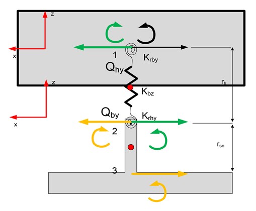
Summing up all the observations conclusion was made that the pipe holder low frequency vibrations could be approximated as shown in Fig. 5.
Fig. 5Estimated pipe holder and pipe segment vibrations
4. Mathematical model
For the sake of simplicity two separate mathematical models will be introduced. First for the vibrations in XZ plane and second – in planes XY, YZ. In more details the second model will be explained.
Pipe holder with pipe segment in plane YZ can be represented as mechanical model in Fig. 6.
Fig. 6Mechanical model (left) and schematic drawing (right) of the pipe holder-pipe imitator system
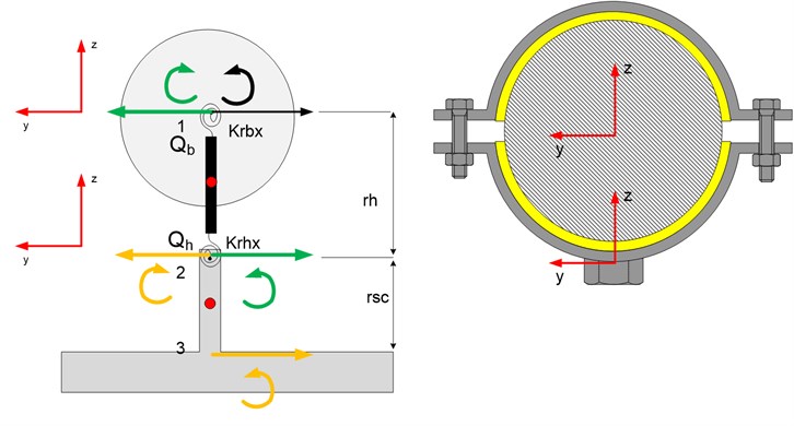
The pipe imitator is approximated as a mass, holder half-rings and their interaction with the pipe is defined as rigidity and damping . Point number 2 at Fig. 6 is a virtual point approximately where screw is welded to the bottom half-ring of the holder. It is defined with the stiffness and damping coefficients.
Mathematical expression of the model shown in Fig. 6 which describes vibrations around axis parallel to X axis can be derived by using formulas of classical mechanics.
Forces acting on pipe imitator :
where – the second order derivative of imitator coordinate, – external force acting in direction of y axis, – the force resulting from the interaction with the "holder" ().
Below is equation which describes movement of the "holder" (see part in Fig. 6) in generalized coordinates:
where – the mass of the "holder", and are the forces acting on it.
Using this principle angular accelerations and rotation momentum are characterized:
where and – the inertial moment and angular acceleration of the pipe imitator () around X axis. – the angular momentum acting on the pipe represented by the imitator, – external angular moment (in our case equals 0).
Equation of rotational motion of the holder:
where – the inertial moment of the holder's part of the model, – the distance from the center of the pipe imitator to the part (see Fig. 6).
The connection between the inclination angle of the components and the displacement coordinate Y, when the small angles are prevalent, is described using next equations:
After differentiating equations (5) and substituting them into formulas (2) and (1), then to (3) and (4), and assuming that rotation momentums and expressed as:
the following expressions are obtained:
where annotations are the angles and the first and the second order derivative of it (angular speed and acceleration). , and , are stiffness and dampings of the model parts, and are moments of inertia around axis of the segments between points 1 and 2 (see Fig. 6) and the pipe imitator, and – masses, – distance as shown in Fig. 6.
Assuming that the moment of inertia is very small compared to the moment of inertia of the pipe segment the equation (8) can be reduced to:
where is pipe segment angular acceleration around axis which is modeled as 1 DOF mechanical system with its own stiffness and damping .
Analyzed vibration type generates only the angular moment at the holder mounting point (point 3 at Fig. 6) and doesn't produce direct force transfer to the mounting point because no vibration along Z axis is generated.
The formulas are given below with the help of which is possible to relate the momentum of rotation at the point number 3 (see Fig. 6) with the rotational oscillations and rigidities of the model components:
angular moment at holder mounting point is expressed as follows:
Mechanical model for the vibration in XZ plane is shown in Fig. 7.
Fig. 7Pipe imitator and holder mechanical model describing vibrations in XZ plane
Mathematical representation of this model is:
XZ plane vibrations' impact on the pipe holder mounting point (wall) can be expressed with two components: angular moment and force perpendicular to the wall:
5. Model identification
In order to apply system identification algorithm, the equations should be derived which relates angular and linear vibrations of the model with the measured accelerations. Equation below describes acceleration of the point which is located at the coordinates on the pipe imitator (this equation is valid only when rotational angles are very small):
With the help of Eq. (14) formula is expressed which describes accelerations of the point which is located at the coordinates on the imitator for the model shown in Fig. 6:
and for the model in Fig. 7:
Eq. (15) indicates that it is possible to distinguish all three components of rotational vibrations by acceleration sensing at different locations and along y axis. For the XZ plane model is not possible to avoid angular velocity constituent which lead to nonlinear system of equations. To avoid this inconvenience angular velocity component is discarded. This step is acceptable as long as the angular velocity's weight to overall acceleration is small.
The grey box system identification principle [7] was used to evaluate the parameters of depicted mechanical models. All underlying identification work was carried on by the System Identification Toolbox (SIT) of the Matlab package. Mathematical models were transformed to state space form to be used in SIT.
An accurate enough initial parameters guess is mandatory for the system identification algorithm to work properly. For 1 DOF equations stiffness can be easily calculated if dampings are discarded, for 2 DOF equations next formula is used (no dampings):
where – are angular frequencies of model's modal vibrations. These frequencies are found from spectral diagrams in Fig. 3(b) or Fig. 4(b) (for and ). Mass of the pipe imitator is and its inertial moment – . Using this principle initial stiffness are calculated, dampings are equated to zero.
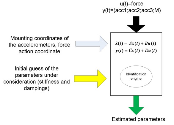
Parameters identification principle is shown in Fig. 8. Force of the hummer impact serves as the input of the model, accelerations and angular momentum acting on foundation are measurements. Hummer impact and sensors coordinates are fed as additional parameters.
Fig. 8A structural diagram of algorithm of applied system identification
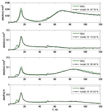
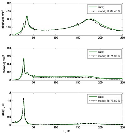
In A part of Fig. 9 fit of the estimated signals to the measured ones (three accelerometers and wall force sensor) when vibrations took place in XZ plane are shown. Experiment was made with holder diameter 78 mm. In figure's B part vibrations took place in planes XY and YZ. Estimated parameters are presented in Table 1.
Table 1Estimated parameters of mathematical models
Parameters for model in Fig. 6 | |||||||
, N/m | , Ns/m | , N/m | , Ns/m | , N/m | , Ns/m | , m | , m |
438.18 | 0.21 | 3804.08 | 0.85 | 989.52 | 0.84 | 0.03 | 0.04 |
Parameters for model in Fig. 7 | |||||||
, N/m | , Ns/m | , N/m | , Ns/m | , N/m | , Ns/m | , m | , m |
351.95 | 0.69 | 846.98 | 0.65 | 1897934.84 | 1338.98 | 0.04 | 0.04 |
Fig. 9In a) part system identification results for model shown in Fig. 6. From the top of the figure: three acceleration measurements and model predicted signals, fourth chart represents measurement and estimated signal of wall force transducer. In b) part system identification result for the system shown in Fig. 7. For model of this type two accelerometers and wall force sensor is enough to accomplish the identification task
a)
b)
6. Conclusion
Two simple mechanical models of the pipe holder element were introduced. With the help of the system identification tools was shown that these models make good approximation of system vibration behavior in low frequency range and can be perfectly exploited for modeling, estimation and parameter evaluation purposes.
References
-
J. C. Wachel, J. D. Tison Vibrations in reciprocating machinery and piping systems. Conference Turbomachinery Symposium, 1994, Texas, USA.
-
Thomas P. Shurtz Analysis of Induced Vibrations in Fully-Developed Turbulent Pipe Flow Using a Coupled LES and FEA Approach. 2009, Brigham Young University.
-
P. Moussou, M. Gaudin, S. Frikha Inverse indentification and updating in vibrations of piping systems. Conference on Inverse Problems in Engineering, 1999, Port Ludlow, WA, USA.
-
Geertruida Susanne Bron-Van Der Jagt Sound Transmission through Pipe Systems and into Building Structures. Ph. D. Thesis, http://alexandria.tue.nl/extra2/200710968.pdf
-
R. Ramanauskas, V. Augutis, M. Malcius, D. Gailius Application of free vibration technique for evaluation of vibro-isolation properties of pipe fixing elements. Journal of Vibroengineering, 2010, Vol. 12, No. 3, p. 256-261.
-
M. Malcius, R. Ramanauskas, V. Augutis Analysis of fastening element impact on pipe modal vibrations. Journal of Vibroengineering, Vol. 13, No. 2, p. 157-162.
-
L. Ljung System Identification: Theory for the User. Prentice Hall, 1987.
About this article

