Abstract
In the current study an analytical model to determine fundamental frequency of perforated plate with circular perforation is formulated. Circular holes are replaced by equivalent square hole and non homogeneity in Young’s modulus and density due to equivalent square perforation is expressed by using unit step functions. Analytical formulation is based on Rayleigh-Ritz method. In present study boundary condition considered is clamped at all edges. The deflected middle surface of the plate is approximated by a function which satisfies the boundary conditions. Proposed approach is validated by comparing numerical analysis results with Finite Element Method (FEM) modal analysis results.
1. Introduction
Study of vibration characteristics of plates is important as plates are one of the most important structural elements used in various mechanical, civil, and aerospace engineering applications, such as bridge decks, hydraulic structures, tube sheets of heat exchanger, ship decks, airplanes, missiles, pressure vessel covers, machine parts and nuclear reactor components. Specially, plates with various complicating effects such as perforations have markedly different behavior than usual homogeneous plates under vibration, as the complicating effect alters the vibration characteristics. From the survey of existing literature authors found that effective elastic constants for the bending of thin perforated plates with triangular and square penetration patterns are suggested by O’Donnell [1]. These equivalent material properties can be used to model perforated plate as equivalent solid plate. Finite element method was used by Forskitt et al. [2] to determine effective Young’s modulus and Poisson’s ratio for a perforated plate with circular holes. They also proposed expressions for equivalent density for plates with regular triangular and rectangular array of holes. By using the concept of equivalent solid plate Choi et al. [3] studied vibration of simply supported perforated plates. They found that values of equivalent elastic constants for dynamics studies are different from static problems to get accurate results. Further they noticed, difference between equivalent elastic properties for static and those for dynamic analysis become significant as the ligament width becomes smaller. Wang and Lai [4] used hybrid approach combining experimental and numerical methods to obtain equivalent material properties. They studied vibrations of perforated plates having rectangular/square and triangular array of holes using the concept of equivalent material properties. Burgemeister and Hansen [5] showed that to predict accurately the resonance frequencies of simply supported perforated panel, effective material constants cannot be used in classical equations. They used cubic function fitted from ANSYS results to determine the effective resonance frequency ratio for large range of panel geometries with an error of less than 3 %. Patil et al. [6] also gave an expression for effective resonance frequency by using curve fitting technique. They used FEM (Finite Element Method) simulation data of resonance frequencies for five perforated plates. The formula is a function of mass remnant ratio, i.e. the ratio of surface area of perforated plate to that of the solid plate for the same dimension. Mali and Singru [7] introduced the concept of concentrated negative masses for perforation holes and determined fundamental frequency of rectangular plate carrying four circular perforations in rectangular pattern. Mali and Singru [8, 9] formulated an analytical model by using unit step functions and greatest integer functions to express non homogeneity in Young’s modulus and density and determined fundamental frequency of free vibration of perforated plate. They have also given details of literature related to non-homogeneous rectangular plates.
From review of the literature, authors have found that no work has been reported dealing with analytical formulation for rectangular perforated plate with an array of circular holes, by considering unit step function to express non-homogeneity due to the holes (in Young’s modulus and density).
In this paper an analytical model to determine fundamental frequency of perforated plate with circular perforations is formulated. Circular holes are replaced by equivalent square hole and non homogeneity in Young’s modulus and density due to equivalent square perforation is expressed by using unit step functions. These functions are used in the analytical model, to determine fundamental frequency. Perforated plate is considered as plate with uniformly distributed mass and holes are considered as non homogeneous patches. Approach presented here is an extension of the approach proposed by Mali and Singru [9]. Rayleigh-Ritz formulation is used to establish an analytical model to determine fundamental frequency. In the present work, fundamental frequency is obtained by numerical analysis with proposed approach for different plate specimens with all edges clamped boundary condition. Numerical analysis involves two cases of 2 mm thickness perforated plate specimens as follows. All specimens analyzed are having rectangular arrays of circular holes.
• Rectangular plates with effective outer dimensions 138 mm × 216 mm × 2 mm and varying perforation sizes.
• Rectangular plates with effective outer dimensions 276 mm × 432 mm × 2 mm and varying perforation sizes.
2. Analytical formulation
2.1. Concept of equivalent square hole for circular perforation
Circular hole can be replaced by square hole of the same area [10] with centre of the square same as the centre of the circular hole. Consider a circular hole of radius as shown in Fig. 1.
For a square perforation of side length , area can be given:
For equivalent square perforation, from equation (1) and (2):
Thus for equivalent square perforation side dimension can be given as:
Fig. 1Equivalent square hole for circle of radius rc
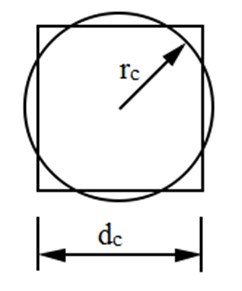
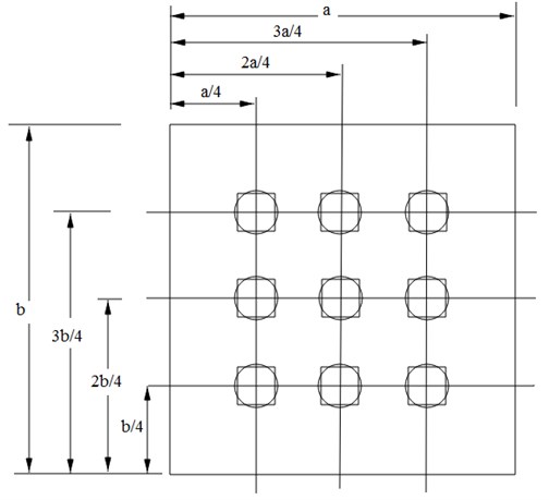
Fig. 2Orientation of the perforated plate with equivalent square perforations
2.2. Formulation of the function to express non-homogeneity in material properties of plates with circular perforations
A rectangular plate with coordinate system , having the origin at one corner is considered as shown in Fig. 2. Co-ordinates of the plate clamped on all edges carrying circular holes are and along and axis respectively. The displacement of an arbitrary point with coordinates on the middle surface of the plate is denoted by , in out-of-plane () direction. The boundary conditions considered here, are all edges clamped. Geometric parameters of the rectangular plate are as and for sides, as thickness and is radius of hole which is uniform for all perforations arranged in rectangular array. It is assumed that transverse defections are small so that the dynamic behavior of the plate is governed by classical thin plate theory.
Equivalent square holes replacing the circular holes are shown in Figure 2 with side dimension as . This is an equivalent approach, to use unit step functions to express non-homogeneity in material properties. Rayleigh-Ritz method is used for the analytical formulation to determine fundamental frequency. Analytical model in the present work does not consider any rotary inertia of the plate.
Consider function representing the variation of the density and modulus of elasticity due to equivalent square perforations. For the function to represent these parameters it must satisfy the following requirements:
The function is constructed as per the geometry of the plates considered with equivalent square perforations. To construct the function we assume that density at any point is the superposition of the density along direction and direction [8, 9], this superposition is also considered for modulus of elasticity.
The functions and represent variation of density and modulus of elasticity along and axes respectively. The functions and are formed by using unit step functions and are superimposed to obtain the function .
The unit step as a function of a discrete variable is given as [11]:
Equations (6) and (7) show the rectangular Heaviside function used to express the non homogeneity in Young’s modulus and density of the plate due to perforations.
Using the above equations for a square perforation pattern can be obtained by the relation [8, 9]:
2.3. Determination of the fundamental frequency of plates with circular perforations
To determine fundamental frequency Rayleigh’s-Ritz method [12, 13] is used. Rayleigh’s-Ritz method is based on the maximum kinetic energy and maximum strain energy of the plate. obtained in section (2.2) is used to obtain the energy expressions given as below.
Maximum value of kinetic energy is given as [13]:
Maximum strain energy is given as [13]:
The middle surface displacement in the above expressions is approximated by using shape function in the form of a series, which satisfies the clamped boundary conditions on the edges 0, , and 0, as given below [13, 14]:
Let us represent the shape function for a rectangular plate with dimensions and in the form:
where are unknown coefficients representing the amplitudes of the free vibration modes and is the product of the pertinent eigenfunctions of lateral beam vibrations.
Each of the in the above equations satisfies at least the geometric boundary conditions. Geometric boundary conditions for the plate are those imposed on displacements and slopes given by equation (12).
For clamped all edges two term deflection function is considered as [15, 16]:
In order to apply Rayleigh-Ritz procedure, maximum strain energy must be equal to maximum kinetic energy, i.e.:
From equations (9) and (10):
where is the integral over the plate area without the frequency.
To use the Rayleighs-Ritz method and expressions are formulated in terms of and , and then frequency is minimized with respect to . Thus are determined so as to obtain the best upper bounds for the fundamental frequency. The frequency minimizing equations are [12]:
Substituting (16) into (17), the following set of minimizing equations can be obtained [12]:
This is a set of 2 simultaneous, linear, algebraic equations in the unknowns and . For a nontrivial solution, the determinant of the coefficient matrix is set equal to zero. The roots of the determinant are the 2 values of . The lowest value of is an upper bound approximation to the fundamental frequency [12].
3. Numerical simulation
To estimate the sensitivity of the proposed approach for various cases of perforation sizes and plate sizes numerical simulation is carried out. All plate specimens analyzed numerically have thickness of 2 mm. Total ten specimens with different sizes of uniform perforations arranged in a rectangular array are considered for numerical simulation. Two sets of plates are analyzed; the first set of plates is having outer effective dimensions as 138 mm × 216 mm and the second set of plates is having outer effective dimensions as 276 mm × 432 mm. Diameter of the perforation in the first set varies over range from 5 mm to 30 mm where as in the second set it varies over range from 10 mm to 65 mm. Side dimensions of the equivalent square perforations for the range of circular holes considered are given in Table 1. Following are the material properties [17] considered for all specimen plates analyzed numerically:
4. Validation of the proposed approach
The proposed analytical model is validated by comparing the numerical analysis results with FEM modal analysis results. FEM modal analysis is carried out by ANSYS 11 using Shell 63 element. Parameters of the plate specimen considered in this study are shown in Table 1. Analysis is carried out for clamped steel plates having 2 mm thickness and carrying nine holes at positions shown in Fig. 2. Meshing is done by free meshing with smart size option and quadrilateral elements are used. Mesh convergence for FEM results is checked for every specimen. This is checked by running different simulations. Final solution is chosen based on the mesh quality as well as mesh size. Thus converged solution is given in Table 1. It is assumed that structure is formed of isotropic homogeneous elastic material, i.e. structural steel with material properties [17] same as used in numerical analysis.
Table 1Fundamental frequency results obtained by numerical and FEM simulations
Specimen No. | (mm) | MRR | (mm) | , numerical (Hz) | , FEM (Hz) | % error |
Specimens with dimensions (138 mm × 216 mm) | ||||||
1 | 4.431 | 0.994 | 2.5 | 696.790 | 693.38 | 0.378 |
2 | 8.862 | 0.976 | 5 | 703.043 | 693.85 | 1.370 |
3 | 13.293 | 0.946 | 7.5 | 714.042 | 695.97 | 2.701 |
4 | 22.155 | 0.851 | 12.5 | 755.054 | 710.17 | 6.909 |
5 | 26.586 | 0.786 | 15 | 802.215 | 724.94 | 10.354 |
Specimens with dimensions (276 mm × 432 mm) | ||||||
6 | 8.862 | 0.994 | 5 | 174.197 | 173.37 | 0.477 |
7 | 17.724 | 0.976 | 10 | 175.760 | 173.46 | 1.326 |
8 | 22.155 | 0.962 | 12.5 | 176.975 | 173.65 | 1.914 |
9 | 44.311 | 0.851 | 25 | 188.763 | 177.53 | 6.327 |
10 | 57.604 | 0.749 | 32.5 | 203.390 | 183.55 | 10.809 |
5. Results and discussion
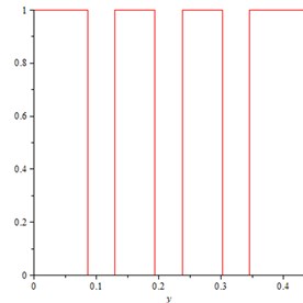
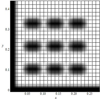
Plots of the functions and are shown in Fig. 3 and Fig. 4 respectively. The nature of the plots of and is same as rectangular waves with amplitude unity. The density plot for the function (for 276 mm, 432 mm and 25 mm) is shown in Fig. 5. The density plot of the function resembles the geometry of the plate considered. The dark area represents the region where 0 which is the region corresponding to perforation. The density plot indicates that is a valid representation of the density and elastic modulus variations for the plate. Table 1 shows the fundamental frequency results obtained by proposed approach and FEM modal analysis. Comparison between the results of FEM and numerical calculations shows that the frequency obtained by the proposed approach is higher than that obtained by FEM. This is because frequency values depend upon the type and the form of the shape function chosen. In present analysis only two term approximation is used for the shape function. The approximate representation of the deflection of the plate given by equation (13) is used for the ease of computations involved in the analysis. Increasing the number of terms will increase the accuracy of the numerical results. Size of circular perforations considered for each specimen is different. The mass remnant ratio (MRR), which is the ratio of mass of perforated plate to the mass of a homogeneous plate with the same effective outer dimensions, is calculated for each specimen as follows:
where is the total number of perforations.
Fig. 3Plot of the function f(x) for specimen 276 mm × 432 mm with rc= 25
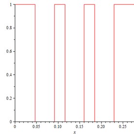
Fig. 4Plot of the function f(y) for specimen 276 mm × 432 mm with rc= 25
From Table 1 it can be observed that mass remnant ratio for each plate specimen considered is different. The distribution of mass and thus the stiffness for each specimen is different.
Results obtained from numerical analysis are reasonably in good agreement with FEM results for plate having MRR more than or equal to 0.852. It is observed from the fundamental frequency results given in Table 1 that, as the MRR decreases, error in the fundamental frequency obtained by the proposed approach becomes higher. It shows that mass distribution pattern approximated by equivalent square perforation deviates more from the actual mass distribution pattern due to circular perforations. This deviation gives maximum error of 10 % in the fundamental frequency obtained by the proposed approach for plate specimens having MRR less than 0.852. For plate specimens having MRR greater than 0.946 the present approach gives results with more accuracy with maximum discrepancy of 2.7 %. Thus the present approach can be used for plate specimens having MRR greater than or equal to 0.852 with maximum error of 6-7 %. Further it can be noticed that with the proposed analytical model results obtained for specimens having approximately close MRR values but different geometrical parameters, accuracy in the results obtained is almost the same (specimen Nos. 1 and 6, specimen Nos. 2 and 7, specimen Nos. 4 and 9).
Fig. 5Density plot of the function F(x, y) for specimen 276 mm × 432 mm with rc= 25
6. Conclusion
In the present work an analytical model to determine fundamental frequency of perforated rectangular plate is formulated. Plates considered for study are having rectangular array of circular perforations. For modeling of material property variation function due to perforation, circular perforations are replaced by equivalent square perforations. With this approximation Heaviside step functions are used to express the variation of material properties of perforated plate. Further analytical model to determine fundamental frequency is formulated by using Rayleigh’s-Ritz method. Numerical analysis is carried out for plate with all edges clamped boundary condition. From the comparison of the FEM and numerical analysis results it is found that the proposed approach can be used for perforated plates with MRR greater than or equal to 0.852 with maximum error of 6-7 % in the fundamental frequency. Present approach can be equally applied to perforated plates with other boundary conditions also.
Structural plates have a multitude of applications in the shipbuilding, aerospace, building and automobile industries. In these industries, complex real-life plate problems may need higher eigenfrequencies to be calculated rather than only fundamental frequency. Theoretical foundations of proposed approach can be further extended to find out the higher eigenfrequencies by using properly chosen shape functions. Thus numerical calculation of the higher frequencies from the proposed approach and their comparison with FEM or experimental results could be an objective of future research.
References
-
O’Donnell W. J. Effective elastic constants for the bending of thin perforated plates with triangular and square penetration patterns. Journal of Engineering for Industry, Vol. 95, 1973, p. 121-128.
-
Forskitt M., Moon J. R., Brook P. A. Elastic properties of plates perforated by elliptical holes. Applied Mathematical Modelling, Vol. 15, Issue 4, 1991, p. 182-190.
-
Choi S., Jeong K. H., Kim T. W., Kim K. S., Park K. B. Free vibration analysis of perforated plates using equivalent elastic properties. Journal of the Korean Nuclear Society, Vol. 30, Issue 5, 1998, p. 416-423.
-
Wang W. C., Lai K. H. Hybrid determination of equivalent characteristics of perforated plates. Experimental Mechanics, Vol. 43, Issue 2, 2003, p. 163-172.
-
Burgemeister K. A., Hansen C. H. Calculating resonance frequencies of perforated panels. Journal of Sound and Vibration, Vol. 196, Issue 4, 1996, p. 387-399.
-
Patil D. C., Gawade S. S., Mali K. D. Dynamic response analysis of rectangular perforated plates with varying sizes of circular perforation holes. 14th International Congress on Sound and Vibration, Ed. B. Randall, Cairns, Australia, 9-12 July 2007.
-
Mali K. D., Singru P. M. Determination of the fundamental frequency of perforated plate with rectangular perforation pattern of circular holes by negative mass approach for the perforation. International Journal of Advanced Materials Manufacturing and Characterization, Vol. 1, Issue 1, 2012, p. 105-109.
-
Mali K. D., Singru P. M. An analytical model to determine fundamental frequency of free vibration of perforated plate by using greatest integer functions to express non homogeneity. Advanced Materials Research, Vol. 622, 2013, p. 600-604.
-
Mali K. D., Singru P. M. An analytical model to determine fundamental frequency of free vibration of perforated plate by using unit step functions to express non homogeneity. Journal of Vibroengineering, Vol. 14, Issue 3, 2012, p. 1292-1298.
-
Younis M. I. Elements of lumped parameter modelling in MEMS. In: MEMS Linear and Nonlinear Statics and Dynamics, First Ed., Springer, ISBN 978-1-4419-6019-1, 2011, p. 132-133.
-
Kreyszig E. Unit step function. In: Advanced Engineering Mathematics, Eighth Ed., John Wiley India Pvt. Ltd., Daryaganj, New Delhi, 2006, p. 265-270.
-
Leissa A. W., Qatu M. S. Vibration of Continuous Systems. First Ed., McGraw Hill Professional, 2011.
-
Chakraverty S. Vibration of Plates. First Ed., CRC Press, Taylor & Francis Group, Boca Raton, 2009, p. 56-135.
-
Szilard R. Theories and Applications of Plate Analysis: Classical Numerical and Engineering Methods. John Wiley & Sons, Inc., Hoboken, New Jersey, 2004.
-
Johri T., Johri I. Analysis of plate vibration under exponentially varying thermal condition. Modern Mechanical Engineering, Vol. 1, Issue 1, 2011, p. 1-5.
-
Laura P. A., Saffell Jr. B. F. Study of small amplitude vibrations of clamped rectangular plates using polynomial approximations. Journal of the Acoustical Society of America, Vol. 41, Issue 4A, 1967, p. 836-839.
-
Armenakas A. E. Appendix ‘A’ Mechanical properties of materials. In: Advanced Mechanics of Materials and Applied Elasticity, CRC Press, Boca Raton, FL, 2006, p. 907-908.
