Abstract
Usage of permanent magnet synchronous machines (PMSM) in wind turbines recently became more of an issue. The development in permanent magnet synchronous machines through the latest technologies, especially about machine design, increases the importance of those machines. Developments in materials technology implement the development of cost effective and profitable products on electric machines and bring simplicity in design. Especially Soft Magnetic Composite (SMC) materials became to be used recently in machine designs due to its advantages such as low costs and providing 3D flux paths. In this work the 2D magnetic equivalent circuit (MEC) of PMSM machine, which includes SMC in its stator part, was composed and stated magnetic equivalent circuit was verified by finite element method. Also torque and radial forces of PMSM were calculated as well. When SMC materials are used in electric machines, flux flows in 3D. 3D finite element method takes quite long time. Due to 2D MEC analysis that was used in our work, the analysis periods become remarkably shorter. Besides the proposed MEC model enables to calculate performances of the machines, which have the desirable slot/pole combinations, correctly. Proposed model is applied on the recently improved fractional slot direct drive synchronous generators.
1. Introduction
As wind turbines become increasingly cost effective their use in the national supply grid increases. Various wind turbine concepts have been developed and built to maximize the energy harnessed, to minimize the cost and to improve the power quality during the last two decades. When focusing on the generator type, the generator system can be classified into electrically excited machines and the permanent magnet (PM) machines. The evolution of wind turbines to industry from mills started in the days of peak oil in 1970s. Associated with that crisis, technologic development became important as well as raw material demand. In early 80s popularity of wind power increased dramatically and wind farms started to be set up. Renewable energy resources became more important not only with the shortage of conventional raw materials, but also the two important issues of energy policy: reliability and sustainability, make it obligatory to use those resources. Within the renewable energy resources, undoubtedly wind power is being used preeminently.
Permanent magnet synchronous machines have high power density and productivity. Permanent magnet synchronous machine may be seen as a machine exciting by a stable excitation current which contains magnets instead of rotor windings of traditional synchronous machine. Hence it acts like a traditional synchronous machine in a condition of fixed-frequency sinusoidal supply on PMSM. Because PMSM doesn’t contain windings on its rotor, loss of excitation on traditional synchronous machine surceases and by this means cooling of the machine becomes easier. There are three main torque components in permanent magnet synchronous motors. These are: moment arises from the interaction of the rotor field and stator currents, reluctance moment related to rotor structure and cogging torque arises from permanent magnets and slots. Within these torques, cogging torque doesn’t contribute to the centering torque although especially at low speeds, the speed conduces to fluctuation and vibration. Surface-mounted permanent magnet synchronous machine does not contain reluctance torque. However its cogging torque is quite high. This torque component leads to torque ripple and increases vibration.
Using fractional slot windings different combinations of numbers of poles and numbers of teeth are possible. However the magnetic field of these windings has more space harmonics, including sub-harmonics. Those unwanted harmonics lead to undesirable effects, such as localised core saturation, noise and vibration, and eddy current loss in the magnets, which are the main disadvantages of these winding types. The radial force density distribution on the stator surface, which results from the air-gap magnetic field under no-load (open-circuit) and on-load conditions, is the main cause of electromagnetically induced noise and vibration. It is important to define properly the magnetic flux density in the air gap of permanent magnet synchronous machine in order to evaluate the performance of machine like analytically obtained moment and Back-EMF. There are many parameters which effect the performance of machine. The feature of materials and the geometrical structure of the machine are the initial ones. Each part needs to be designed for the preliminary design. The design of those machines is related to the proper calculation of characteristics of preliminary designs. The geometry of the machine and the excitation of the stator windings affect the distribution of the magnetic field thereby influencing the torque. The other existing force component in the PMSM is the radial force which can potentially cause the radial vibrations in the stator. As mentioned the torque components are dependent upon the distribution of the magnetic field in the air gap [1].
Recently SMC materials were used in a lot of AC applications like motors, transformers and sensors [2]. New Soft Magnetic Composite Materials (SMC) have a lot of advantages compared to conventional laminated steel in electromagnetic systems applications [3]. The most important ones of these advantages:
• being isotopical magnetic and thermal materials,
• having low eddy losses,
• having low total losses at medium and high frequencies.
In this study radial forces, Back EMF and torque of SMC permanent magnet synchronous machine are analyzed with two dimensional magnetic equivalent circuit theorem. The analyzed machine has 9 slots and 10 poles. SMC material and conventional steel are compared in this study.
2. Properties of SMC material
The main structure of SMC is bounded steel particules with high purity. These particules are bounded with organic material coating. Coated particules are pressed into rigid material using swage. Materials of this kind are usually magnetic isotopical because of being natural particle and this makes it easy to design [2-3]. SMC include iron particules coated with dielectric film. These iron particules spared each other with electrical insulation. Because of this, this kind of materials has high electric resistance. These materials are structured with pressing the particules. The resistivity of SMC depends on SMC’s mechanical and ferromagnetic characteristics, dimensions and density of iron particules, insulation material, pressing process and thermal behaviour. SMC material’s magnetic and mechanical characteristics depend not only on iron particules, but also on the oil and resin amount and cold or hot press process. If SMC material is unsintered, endurance will be low compared to laminated SMC or sintered SMC. SMC material’s characteristics can be made suitable for special applicaitons [4-5]. A schematic diagram of the component elements of a powder core is shown in Figure 1.
Isotopical magnetic characteristics provide flux density in rotor magnetic circuit in axial direction, thus motor’s total axial length can be reduced without any loss in motor performance [7]. Magnetic circuits produce three dimensional flux lines and different radial topologies are used in order to obtain high motor performance [2]. Because of the three dimensional flux distribution of SMC materials, teeths can be extended axial, thus flux is increased on teeths and rotor yoke. With this kind of design air gap active length became max [7]. SMC material is convenient especially for 3D flux machine structure [8]. In addition, it cancels the lamination’s magnetic field limitations. Because of the isolation of iron particules by surface coating and coherents, it has lower eddy losses than laminated steel especially in high frequencies. At total loss, hysteresis losses are higher. By the increase of exciting frequency, the increase of the SMC’s core losses is lower than in the electrical steel. SMC materials are very useful for motor operating at high frequencies, but at low and medium frequencies they are not as good as high degree laminated electrical steel. SMC is proper for large scale motors with low prices.
Fig. 1A schematic diagram of the component elements of a powder core [6]
![A schematic diagram of the component elements of a powder core [6]](https://static-01.extrica.com/articles/14553/14553-img1.jpg)
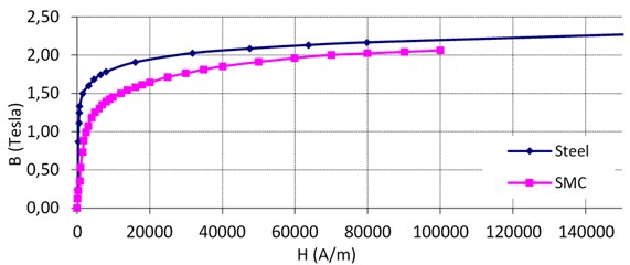
Fig. 2The comparison of B-H curves related to electrical steel and SMC material
There are a lot of studies in literature about development of SMC material’s two important characteristics. These two characteristics are:
• increasing the purity and decreasing the deformation between particules by decreasing coersivity force and increasing magnetic particule’s magnetic permeability,
• increasing the density, electrical resistance and thermal resistance under pressure [3].
For laminated silicon steel core machines good magnetic characteristics can be obtained through the plane flux line. This provides a two dimensional magnetic circuit. SMC insulator coating has isotropic magnetic characteristics. Thus three dimensional flux line can be obtained from electrical machines designed with this material.
SMC material’s saturation is related to composite, purity and density. Saturation flux density, SMC material’s relative permeability and induction are lower than of the silicon steel. Induction is related to permeability in low magnetic fields. Saturation is important in high magnetic fields. Due to having low induction MMF can be increased by increasing the flux in the core, thus teeth area can be extended. Extention of teeth area is not possible without increment of slot opening, thus extention of teeth area enlarges the motor dimensions. The best way to increase the MMF is to use a permanent magnet with higher coercivity [8, 9]. Another method is changing of the SMC material’s structure. While prepareing the SMC material, if an external flux interaction can be provided, permeability will be increased and magnetic resistance will be decreased. This method is called external flux interaction. With this method steel losses of SMC can be decreased to 6.25 % [10]. The magnetization curves of SMC and silicon steel are shown in Figure 2.
3. 10 pole 9 slots SMC malzemeli permanent magnet sychronous generator MEC analysis
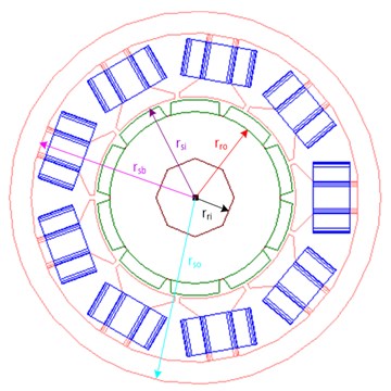
Two dimensional cross-section of machine is shown in Figure 3. The stator has windings concentrated around each stator pole. The number of winding turns of each phase is 216. The rare-earth magnet “Nd-Fe-B” is buried in the rotor iron. Residual magnetic flux density and coercive force of the permanent magnet are about 1.3 T and 1000 kA/m, respectively. The following assumptions have been made for the analysis provided:
• the used materials have homogeneous properties,
• ,
• firstly no load is applied,
• the stator teeth and permanent magnets are rigid; no deformation due to radial and tangential force is experienced by these components,
• hysteresis and eddy currents are neglected,
• current is taken as sinusoidal,
• SMC material is used in stator core.
Fig. 32D cross-section of the permanent magnet synchronous machine
For MEC method, first it is studied in the no load condition.
Before Back-EMF calculation, air-gap flux density () is found by the solution of MEC at Figure 4 as:
where is the reluctance of the magnet, is the reluctance of air gap, is the reluctance of rotor, is the reluctance of stator, is leakage reluctance and is the leakage factor and its value is less than one.
Fig. 4MEC for slotted structure at no load condition
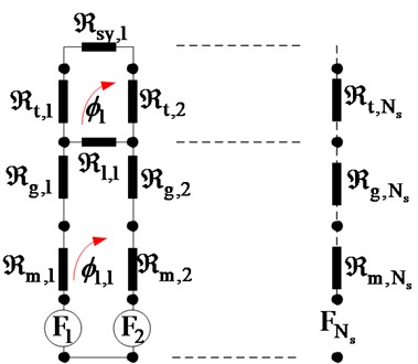
Here are:
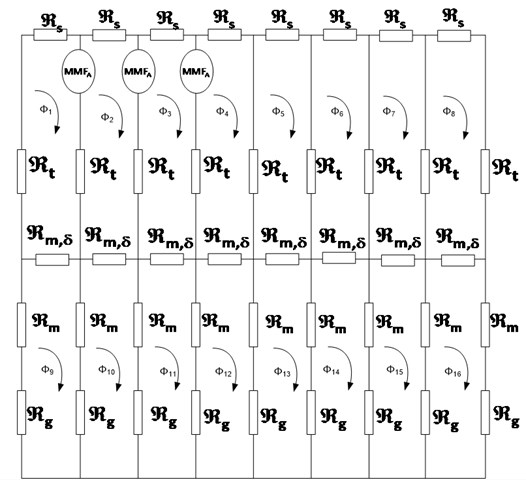
Second it is studied on load condition. The following equation is used in order to obtain the number of MEC column at load condition:
The magnet reluctance [A/Wb] and gap reluctance [A/Wb] are calculated different from the no-load model magnet reluctance, because the armature reaction flux crosses the air gap and magnets over one slot pitch [m] (see Fig. 5):
Total flux:
Here are:
Fig. 5MEC at load condition
4. 10 pole 9 slots SMC malzemeli permanent magnet sychronous generator FEA analysis
This machine is analysed by the software Flux 3D. The rotor air gap flux density and the motor torque value are calculated. In order to compare the performance of motors with different materials, the PMSM with SMC material and the PMSM with steel M19 material have the same stator and rotor structure with the same size, the rated power of the two motors are both 1.5 kW. The dimensions related to rotor and stator are shown in Table 1 and Table 2. In Fig. 6 the stator slot is shown.
Table 1Stator parameters of the PMSM
Stator inner radius | 20.6 mm |
Stator outer radius | 38 mm |
Airgap length | 0.6 mm |
Airgap width | 7.5 mm |
Table 2Rotor parameters of the PMSM
Rotor inner radius | 8 mm |
Rotor outer radius | 20 mm |
Magnet length | 2.5 mm |
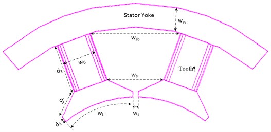
Fig. 6. Stator slot dimensions
In Fig. 7 magnetic flux density is shown for both SMC material machine and steel machine. As it can be seen from the figures SMC machine has a lower magnetic flux density. Thus torque and Back EMF values would be lower, but the decrement of torque and Back EMF is very small. Also see data in Table 3 and Table 4.
Fig. 7a) Flux density of permanent magnet sychronous machine with steel stator, b) flux density of permanent magnet sychronous machine with SMC stator
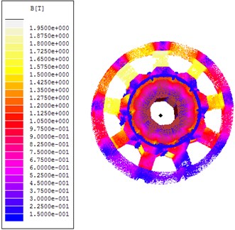
a)
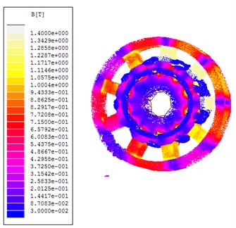
b)
Table 3The comparison of FEA and MEC for SMC machine
For steel | FEM | MEC |
1.15 | 1.1 | |
1.8 | 1.77 | |
1.5 | 1.45 |
Table 4The comparison of FEA and MEC for steel machine
For SMC | FEM | MEC |
1.05 | 1.0 | |
1.4 | 1.35 | |
0.8 | 0.75 |
5. Winding structure
The winding array effects the performance of electric machines, back electromotive force in particular. The winding type of an electrical machine is determined by the number of , slot per pole per phase of the machine following the below regulars:
• integral , integral-slot distributed winding,
• , integral-slot concentrated winding,
• fractional , fractional-slot distributed winding,
• fractional , fractional-slot concentrated winding.
The distributed winding is the most common configuration for large electrical machines. With one slot per pole per phase, its winding factor is equal to 1. Concentrated windings can present the drawback of a low winding factor and high torque ripple. The advantages of this configuration are the shorter end-windings and the simple mounting [13].
There are many works on generating concentrated winding method. J. Cross and P. Vigoure presented specialized concentrated two layer windings [14]. The winding configuration vectors are derived in seven steps:
1. For the values less than 1; , slot per pole per phase, reduces till two non divisible integers .
2. Repeatable series of 0 and 1 sequence are found by the equality above. Initial repeatable sequence is obtained by this equation: .
3. Initial sequence is to be permuted in a manner that the 1 s must be distributed regularly among 0 s.
4. Permutated sequence is written side by side 3 times.
5. Classical sequence is in the form of A+C-B+A-C+B-.
6. First layer of winding is arrayed by the correspondence of 1 s.
7. Second layer of winding is attained by shifting the first line as far as a screw pitch.
A winding structure is designed for the 9 slot and 10 pole configuration in this study: . In this situation there will be 3 ones and 7 zeros in the sequence.
(1) Initial sequence: 0000000111.
(2) Optimum sequence: 1001001000.
(3) Permutated sequence is written side by side 3 times: 1001001000|1001001000|1001001000.
(4) Classical sequence: A+C-B+A-C+B-:
1 0 0 1 0 0 1 0 0 0 1 0 0 1 0 0 1 0 0 0 1 0 0 1 0 0 1 0 0 0,
A+C-B+A-C+B- A+C-B+A-C+B- A+C-B+A-C+B- A+C-B+A-C+B- A+C-B+A-C+B-.
(5) The first layer of winding will be ordered as come up to number 1:
A+ A- A+ C+ C- C+ B+ B- B+.
(6) The second layer of winding is obtained by shifting the first line about a tooth:
A+ A- A+ C+ C- C+ B+ B- B+,
A- A+ A- C- C+ C- B- B+ B-.
(7) The last winding structure can be drawn as below (see Fig. 8).
Fig. 8Winding structure for 9 slot and 10 pole configuration

6. Permanent magnet sychronous generator radial force analysis
The most frequent source of vibration in permanent magnet synchronous machine is caused by radial force due to the electromagnetic force. The problems of vibration and noise are extremely troublesome when the forcing frequencies of the radial force match one or more of the mechanical or structural resonant frequencies in the machine. Therefore it isimportant to know the air gap flux density distribution accurately for the prediction of Back-EMF waveform, cogging torque and radial force [15]. An alternative to deriving the electromagnetic torque using an energy balance approach is to derive the components of force from the magnetic field using a Maxwell Stress Tensor method. Specifically, within the airgap of the machine the local radial components of force density can be expressed [16]:
where , , and denote the tangential and radial flux densities created by the PM and stator windings respectively. If for the structure that is being discussed in this work a winding structure for 9 slot 10 pole configuration is generated, the equation (23) can be put forth like below as the tangential force is of a negligible level in comparison with the radial force:
The radial force equality is generated after the magnetic flux density is generated through the equality above.
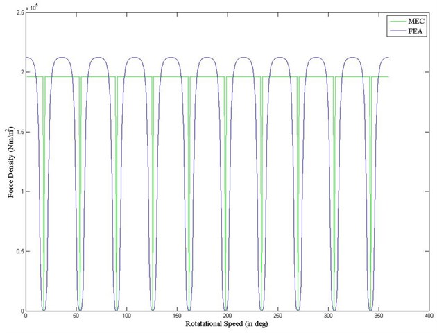
After magnetic flux density is obtained from the above equations, radial force is obtained from equation (26) (see Fig. 9).
Fig. 9Radial force from FEA and MEC
7. Permanent magnet sychronous generator torque analysis
Cogging torque and electromagnetic torque of a PM machine are calculated according to Maxwell’s stress tensor method as:
According to Arkkio’s method, it is better to compute the average value of the electromagnetic torque over the entire air-gap surface. So the torque can be calculated as:
where is air gap surface constituted by the layers between stator and rotor, is air gap length. According to virtual work method, electromagnetic torque is equal to the derivative of the magnetic co-energy Wm with respect to rotor angle at constant current [17]:
According to equation (29) it is obtained:
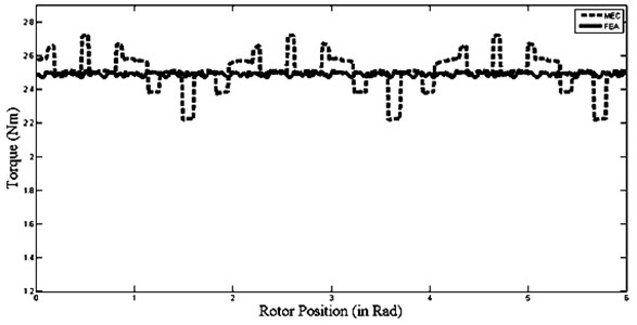
According to the torque results given in Figure 10, the difference between the results of MEC and FEA is less than 1 % when steel is used in stator and according to the torque results given in Figure 11, the difference between the results of MEC and FEA is 2 % when steel is used in stator.
Fig. 10SMC-PMSM torque wave form
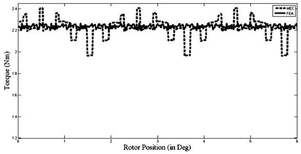
Fig. 11Steel-PMSM torque wave form
8. Conclusions
After magnetic flux distribution was found by magnetic equivalent circuit method, radial force density and torque were calculated. As seen in Figure 10 and Figure 11, it is observed that torque decreased by 12.5 % when SMC material is used in the stator of PMSMs. Since the SMC material is cost efficient and it doesn’t have any mold cost during the production phase, SMC material is much more cost-effective in comparison with steel. Moreover the labor cost is lower because it is more shapeable.
When the torque results obtained by magnetic equivalent circuit method and by finite element method are compared, it is seen that the difference isn’t more than 2 %. Radial forces of the investigated machine are very low. Because of that ripple and vibrations are remarkably low. Radial forces are directly proportional to the square of air-gap flux density. When the air-gap flux density increases, radial forces increase. At the same time the power obtained from the machine increases as well. Nominately radial forces must be taken into account when the machine optimization is done. Thereby the vibration and torque resonance of the machine become decreased. A combination of analytical and FEA methods is used during the analysis of radial forces.
References
-
Khoobroo A., Fahimi B., Pekarek S. D. A new field reconstruction method for permanent magnet synchronous machines. Industrial Electronics, IECON 2008, 2008, p. 2009-2013.
-
Zhu J., Guo Y. Study with magnetic property measurement of soft magnetic composite material and its application in electrical machines. Industrials Application Conference, IEEE, Australia, 2004.
-
Maeda T., Toyoda H., Igarashi N., Hirose K., Mimura K.,Nishioka T., Ikegaya A. Development of super low iron-loss P/M soft magnetic material. SEI Technical Review, No. 60, June 2005, p. 3-9.
-
Khan M. A., Dosiek L., Pillay P. Design and analysis of PM wind generator with a soft magnetic composite core. IEEE Symposium on Industrial Electronics, 9-13 July 2006, Vol. 3, 2006, p. 2522-2527.
-
Hultman L. O., Jack A. G. Soft magnetic composites – materials and applications. IEEE International Conference on Electric Machine and Drives, 1-4 June 2003, Vol. 1, 2003, p. 516-522.
-
Shokrollahi H., Janghorban K. Soft magnetic composite materials (SMCs). Journal of Materials Techonology, 2007, p. 1-12.
-
Cros J., Viarouge P., Halila A. Brush DC motors with concentrated windings and soft magnetic composites armatures. Industry Application Conference, Vol. 4, 30 Sep. – 4 Oct. 2001, p. 2549-2556.
-
Guo Y. G., Zhu J. G., Watterson P. A., Wu W. Comparative study of 3D flux electrical machines with soft magnetic composite cores. Industry Application Conference, Vol. 2, 13-18 Oct. 2002, p. 1147-1154.
-
Chebak A., Viarouge P., Cros J. Analytical model for design of high-speed slotless brushless machines with SMC stators. IEEE International Conference on Electric Machine and Drives, Vol. 1, 3-5 May 2007, p. 159-164.
-
Marucci M. L., Narasimhan K. S. Advances, Applications, and Opportunities for Coated Iron Powder for Electromagnetic Applications, Hoeganaes Corporation, Cinnaminson, NJ.
-
Cha H. R., Lee K. S. K., Yun C. H., Lee S. H. Magnetic properties of soft magnetic composite using external flux impression method. Journal of Optoelectronics and Advanced Materials, Vol. 10, Issue 17, 2008, p. 87-1791.
-
Chen A., Nilseen R., Nysveen A. Harmonic analysis and comparison of the back EMFs of four permanent magnet machine with different winding arrangements. ICEMS, 2008, p. 3043-3048.
-
Libert F., Soulard J. Design Study of a Direct-Driven Surface Mounted Permanent Magnet Motor for Low Speed Applicatıon. KTH Report, 2003.
-
Cros J., Viarouge P., Halila A. Synthesis of high performance PM motors with concentrated windings. Technical Report, IEEE Transaction on Energy Conversion, Vol. 17, No. 2, 2002.
-
Chun Y. D., Lee J. The permanent magnet overhang effect on the radial force density in brushless DC motor. Journal of Electrical Engineering, Vol. 2, 2012, p. 1-4.
-
Zhu W., Pekarek S., Fahimi B., Deken B. J. Investigation of force generation in a permanent magnet synchronous machine. IEEE Transaction on Energy Conversion, Vol. 22, Issue 3, 2007, p. 557-565.
-
Vu Xuan H., Lahaye D., Ani S. O., Polinder H., Ferreira J. A. Effect of design parameters on electromagnetic torque of PM machines with concentrated windings using nonlinear dynamic FEA. International Electric Machines & Drives Conference, Niagara Falls, ON, 2011, p. 383-388.
About this article

The authors are indebted to Yildiz Technical University Scientific Project Unit (BAP) for providing financial support.
